HAL Id: tel-03230102
https://hal.univ-lorraine.fr/tel-03230102
Submitted on 19 May 2021HAL is a multi-disciplinary open access archive for the deposit and dissemination of sci-entific research documents, whether they are pub-lished or not. The documents may come from teaching and research institutions in France or abroad, or from public or private research centers.
L’archive ouverte pluridisciplinaire HAL, est destinée au dépôt et à la diffusion de documents scientifiques de niveau recherche, publiés ou non, émanant des établissements d’enseignement et de recherche français ou étrangers, des laboratoires publics ou privés.
Nanostructured Redox-Active Mesoporous Silica Films
Based on An Electron-Hopping Mechanism : Charge
Transfer Behaviors And Energy Storage Potentials
Jianren Wang
To cite this version:
Jianren Wang. Nanostructured Redox-Active Mesoporous Silica Films Based on An Electron-Hopping Mechanism : Charge Transfer Behaviors And Energy Storage Potentials. Analytical chemistry. Uni-versité de Lorraine, 2020. English. �NNT : 2020LORR0216�. �tel-03230102�
AVERTISSEMENT
Ce document est le fruit d'un long travail approuvé par le jury de
soutenance et mis à disposition de l'ensemble de la
communauté universitaire élargie.
Il est soumis à la propriété intellectuelle de l'auteur. Ceci
implique une obligation de citation et de référencement lors de
l’utilisation de ce document.
D'autre part, toute contrefaçon, plagiat, reproduction illicite
encourt une poursuite pénale.
Contact : [email protected]
LIENS
Code de la Propriété Intellectuelle. articles L 122. 4
Code de la Propriété Intellectuelle. articles L 335.2- L 335.10
http://www.cfcopies.com/V2/leg/leg_droi.php
A thesis:
Nanostructured Redox-Active Mesoporous Silica Films Based on An
Electron-Hopping Mechanism: Charge Transfer Behaviors And
Energy Storage Potentials
by
Jianren Wang
For obtaining a Doctoral title Major: Chemistry (Doctoral school C2MP)
Public defense scheduled on 2 December 2020 in front of the jury: Supervisor:
Dr. Neus Vilà — Lecturer (LCPME, Université de Lorraine) Co-supervisor:
Dr. Alain Walcarius — Research Director (LCPME, Université de Lorraine) Reviewers:
Pr. Patrice Simon — Professor (CIRIMAT, Université Toulouse Ⅲ) Pr. Christel Laberty-Robert — Professor (LCMCP, Sorbonne Université) Examiners:
Pr. Laurent Ruhlmann — Professor (ICS, Université de Strasbourg) Dr. Vanessa Fierro — Research Director (IJL, Université de Lorraine)
Films de silice mésoporeux nanostructurés redox actifs basés sur un
mécanisme de saut d'électrons: comportements de transfert de
charge et perspectives de stockage d'énergie
Sujet de thèse : Présenté par
Jianren Wang
Pour l’obtention de titre de Docteur Spécialité: Chimie (Ecole doctorale C2MP)
Soutenance publique prévue le 2 Décembre 2020 devant le jury: Directrice:
Dr. Neus Vilà — Maître de Conférences (LCPME, Université de Lorraine) Co-directeur:
Dr. Alain Walcarius — Directeur de Recherche (LCPME, Université de Lorraine) Rapporteurs:
Pr. Patrice Simon — Professeur (CIRIMAT, Université Toulouse Ⅲ) Pr. Christel Laberty-Robert — Professeur (LCMCP, Sorbonne Université) Examinateurs:
Pr. Laurent Ruhlmann — Professeur (ICS, Université de Strasbourg) Dr. Vanessa Fierro — Directeur de Recherche (IJL, Université de Lorraine)
- i -
Acknowledgements
First and foremost, I hereby extend my thanks to my supervisors. Neus Vilà, thank you for the countless hands-on experimental guidance, numerous efforts for the materials characterizations, as well as endless tolerance for the mistakes I made. Alain Walcarius, your profound knowledge and rigorous scholarship have a deep influence on me, and I have also learned a lot of writing skills from the corrections you made for my drafts. Just as a famous saying, the mind is not a vessel to be filled but a fire to be kindled. The last three years working with you cultivate my interest of science, improve my ability to solve problems, and broaden my horizons, with which I believe I can go farther in my future life.
I would like to express a special gratitude to Liang Liu, whose lofty academic attitude and solid theoretical foundation always inspire me to strive for excellence. Your heart-to-heart talks and guidance always sustain me especially when I was not confident in moments of difficulties. Moreover, I would like to thank to the people who support my experiments: Mathieu Etienne for the SEM measurements; Claire Genois for the
compound supply; Gérard Paquot and Jean-Paul Moulin for the Machining
assistance; Jérôme Grausem for the FTIR set-up;Grégory Francius for AFM images;
Manuel DOSSOT for the Raman spectra; and Aurélien RENARD for the XPS and Nitrogen Adsorption-desorption testes. I also feel grateful to Grégoire Herzog, Christelle Despas, Marc Hebrant, and Michel Perdicaki for the stimulating discussions during regular group meetings. Without your support and encouragement, I would not have been able to complete this thesis in time.
Then my thanks comes to my lab-mates from all over the world: Samuel,
Himanshu, Ning, Taisiia, Mengjie, Guofeng, Deomila, Joanna, Mariela, Wahid,
Magdalena, Huong, Martha, Christelle, and José. I cannot forget the parties we ever hold and the drinking time in bars, with endless topics from the culture difference to the international situation, from the experimental plan to the trip experience. I realized how
privileged I am to get the chance to work with you. The joyful days and cheerful
moments we spent together will always be treasured in my memory. With your company, I never felt lonely in the days aboard and I greatly enjoyed the time with you guys!
- ii -
Likewise, I would like to express my sincere thanks for my friends in Nancy. Just to name a few of them (please forgive me for not being able to list all of them): Shengzhao Pang, Ruotao Yang, Zhang Zhao, Yajun You, Kou Du, Hang Wan, Anji Ma, Yuan Chu, Tao Wang, and many others. Your company brought a lot of joy to my life in the past three years. I also would like to say thanks to my landlady Collet Dubas who always invited me to her family meal and took care of me these years, which really let me feel at home.
I would like to give my sincere thanks to my parents: Yingmao Wang and Yufeng Wang. Like many Chinese students of my generation, I am the only child of my family. My parents have dedicated their entire lifetime to nurture and educate me, without asking for anything in return. I hope that I have not let my parents down so far and that they would be able to talk about me with pride. I also want to thanks to my girlfriend Tian Li, who encouraged me to go aboard to experience a different life and patiently comfort me when I was down.
- iii -
Table of Content
Abstract ... 1
Résumé ... 3
Objectives of This Thesis ... 9
Chapter Ⅰ ... 10
Introduction ... 10
1.1 Development history of supercapacitors ... 11
1.2 The main evaluation indicators for capacitors ... 13
1.3 The energy storage mechanisms of supercapacitors ... 14
1.4 The features of batteries and supercapacitors ... 17
1.5 The criteria to distinguish pseudocapacitive materials and battery-type materials ... 21
1.6 The research trend in the field of the energy storage electrodes ... 24
1.7 Electron-hopping as the mechanism to achieve redox reactions ... 30
1.8 The fabrication of ordered mesoporous silica-based materials and their applications ... 32
Chapter Ⅱ ... 42
Electron-Hopping System Constructed with Vertically-Aligned Mesoporous Silica Films: The Potential and Influence Factors for Energy Storage Applications ... 42
2.1 Introduction ... 42
2.2 Experimental section ... 44
2.3 Results and discussions ... 46
3.4 Conclusions ... 68
Chapter Ⅲ ... 69
Construction of the Ferrocene Functionalized Mesoporous Silica Film on Graphene/Graphite 3D Architectures with Enhanced Energy and Power Densities 69 3.1 Introduction ... 69
3.2 Experimental section ... 71
3.3 Results and discussions ... 72
3.4 Conclusions ... 93
- iv -
Fabrication of Flexible Planar Micro-Devices Operating with Electron-Hopping
Mechanism for Energy Storage Applications ... 95
4.1 Introduction ... 95
4.2 Experimental section ... 97
4.3 Results and discussions ... 99
4.4 Conclusions ... 114 General Conclusions ... 115 Conclusions Générales ... 116 High Lights... 117 Outlook ... 118 References ... 123 Appendix ... 151 Chemicals ... 151 Characterization apparatus ... 152
- 1 -
Abstract
Electrical conductivity has always been a most fundamental element for energy storage electrodes. Because of this, there were only few attempts to use the insulating materials (i.e., silica, and anodized aluminium etc.) in the energy storage field despite their advantages including controllable and well-organized nanostructures, environmental benign properties, facile methods of synthesis, large surface area, as well as low cost. Electron-hopping, a special electron conduction mechanism, allows electrons to transfer among adjacent and close enough redox molecules directly without requiring the conductivity of supporting materials. This unique charge transfer feature makes possible the use of insulating materials for energy storage after functionalizing their surface with redox-active molecules. This thesis is focused on the: 1) demonstration of the feasibility of a novel idea to construct energy storage materials with a demo of redox-molecules functionalized silica film deposited on ITO electrode; 2) achievement of a large-scale assembly of such silica film on graphene substrate which possesses a high surface area; 3) development of the prototype of flexible planar devices.
First, the redox-active and vertically-aligned mesoporous silica thin films were prepared on indium-tin oxide electrode from the combination of an electrochemically-induced self-assembly method (to generate azide functionalized silica) and a copper-catalyzed azide-alkyne click reaction (to derivatize the material with electroactive groups). Such insulating silica films composed of uniformly distributed vertical mesochannels (pore diameter: 2 nm) provide a large surface area to accommodate the redox active species, such as ferrocene, on the surface of silica walls. Besides, the density of the redox molecules can be easily varied by tuning the composition of silane
precursors (3-azidopropyl triethoxysilane, and tetraethoxysilane) in the starting
solution. These features make such organic-inorganic films an ideal platform to evaluate the energy storage potential, and the factors influencing the electron-hopping
- 2 -
process. The most effective system is the ferrocene-functionalized silica film prepared
from 40% organosilane, which is able to deliver a capacity of 105 C cm-3 (1.10 mC cm
-2) at a current density of 0.4 A cm-3. (with up to 48% capacity retention achieved at a
short charging time of 2.8 s).
The ITO substrate can only provide limited area for the growth of the mesoporous silica film, restricting energy and power density of the final electrode. Therefore, the extensive assembly of such redox-active silica film has been further done by using a large surface area electro-exfoliated graphene as the current collector to study its interest in delivering fast redox reactions over a large-scale (contrary to monolayer-based electroactive system generated on the ITO electrode). Multiple characterization techniques have been used to analyze the obtained electrode (labelled as Fc-MS@EG). It proves a uniform deposition of the ferrocene functionalized mesoporous silica thin film on the few-layers graphene. As a result, a sandwich structure with a thickness ~70 nm was formed. Compared with the ITO counterpart, the Fc-MS@EG can deliver ~200
times higher specific capacity of 196 mC cm-2 (326 mF cm-2) at a current density of 2
mA cm-2, and 69% capacity retention even at 3800 C, which is much better than the
traditional faradic materials.
An attempt to fabricate a flexible planar micro-device operating with the electron-hopping mechanism has been done through generating the ferrocene functionalized silica film on the flexible graphene electrode. With this aim, a systematic preparation protocol is proposed including transfer of a thin layer of graphite on scotch tape, 3D printing assisted patterning, electro-exfoliation of graphite, and following deposition of the silica layer, and click chemistry. The preliminary results prove the feasibility of this protocol, and the obtained planar electrode shows a high flexibility thanks to the scotch
tape substrate. It also delivers a high capacity of 24.5 mC cm-2 at a current density of
0.5 mA cm-2, and good rate performance of 81% capacity retention at a current density
- 3 -
Résumé
Les progrès rapides de la société et l'augmentation constante des besoins matériels
entraînent une consommation explosive de sources d'énergie non renouvelables, telles
que le pétrole et le charbon, qui peuvent difficilement répondre à la demande dans un avenir proche. En outre, le processus d'extraction et la consommation de ressources
énergétiques fossiles ont également entraîné de graves problèmes environnementaux et
climatiques en raison des émissions de carbone et des rejets de dioxyde d'azote et de dioxyde de soufre, etc. Par conséquent, le développement et l'utilisation des sources d'énergie renouvelables est une voie inévitable pour le développement durable de la société au 21e siècle. De nouvelles sources d'énergie, notamment l'énergie éolienne, l'énergie solaire et l'hydroélectricité, ont été exploitées ces dernières années. Cependant, le caractère intermittent et la répartition géographique inégale de ces nouvelles sources d'énergie posent des difficultés pour leur utilisation pratique directe, et il faut donc des dispositifs de stockage de l'énergie pour une utilisation efficace, sûre et fiable de ces sources. Les batteries secondaires au lithium-ion à haute densité énergétique (près de 180 Wh/kg) sont actuellement les dispositifs de stockage d'énergie électronique les plus utilisés, mais le processus relativement lent d'intercalation des ions lithium en phase solide limite leur densité de puissance. En revanche, les supercondensateurs peuvent fournir une densité de puissance beaucoup plus élevée (10 kW/kg), d'excellentes performances de débit, une longue durée de vie et une large plage de températures d'utilisation. Par conséquent, l'amélioration de la densité énergétique des supercondensateurs et la réalisation de caractéristiques supplémentaires (par exemple, la transparence, la flexibilité et la microminiaturisation) pour répondre aux demandes de stockage d'énergie de plus en plus massives et variées sont les tendances de développement croissantes.
La conductivité électrique a toujours été un élément fondamental pour les électrodes de stockage d'énergie. C'est pourquoi il n'y a eu que peu de tentatives d'utilisation des matériaux isolants (silice, aluminium anodisé, etc.) dans le domaine du stockage de
- 4 -
l'énergie, malgré leurs avantages, notamment des nanostructures contrôlables et bien organisées, des propriétés respectueuses de l'environnement, des méthodes de synthèse faciles, une grande surface et un faible coût. Le saut d'électrons, un mécanisme spécial de conduction des électrons, permet aux électrons de se transférer directement entre les molécules redox adjacentes sans avoir besoin de la conductivité des matériaux de support. Cette caractéristique unique de transfert de charge permet d'utiliser des matériaux isolants pour le stockage de l'énergie après avoir fonctionnalisé leur surface avec des molécules redox actives. Cette thèse porte sur le : 1) la démonstration de la faisabilité d'une nouvelle idée pour construire des matériaux de stockage d'énergie avec une démonstration de molécules redox fonctionnalisées sur un film de silice déposé sur une électrode ITO ; 2) la réalisation d'un assemblage à grande échelle sur un substrat de graphène qui possède une surface élevée ; 3) le développement du prototype de dispositifs planaires flexibles.
Tout d'abord, les couches minces de silice mésoporeuse fonctionnalisée de molécules redox ont été préparées sur une électrode d'oxyde d'indium-étain à partir de la combinaison d'une méthode d'auto-assemblage induite électrochimiquement (pour générer de la silice fonctionnalisée par un azide) et d'une réaction de clic azide-alcyne catalysée par le cuivre (pour dériver le matériau avec des groupes électroactifs), comme l'illustre la Figure 1. Ces films de silice isolants composés de mésocanaux verticaux uniformément répartis (diamètre des pores: 2 nm) offrent une grande surface pour accueillir les espèces redox actives, telles que le ferrocène, à la surface des parois de silice. En outre, la densité des molécules d'oxydoréduction peut être facilement modifiée en ajustant la proportion d'azide-silane dans la solution de précurseur. Ces caractéristiques font de ces films organique-inorganique une plateforme idéale pour évaluer le potentiel de stockage de l'énergie et les facteurs influençant le processus de saut d'électrons. Le système le plus efficace est le film de silice fonctionnalisé au ferrocène, préparé à partir d'organosilane à 40%, qui est capable de fournir une capacité
de 105 C cm-3 (1,10 mC cm-2) à la densité de courant de 0,4 A cm-3. (avec une rétention
- 5 -
Figure 1. Illustration schématique du processus de préparation des couches minces de silice mésoporeuse à fonctionnalisation ferrocène, alignées verticalement, sur un morceau d'électrode ITO plate.
Le substrat ITO ne peut fournir qu'une surface limitée pour la croissance du film de silice mésoporeux, ce qui limite son énergie finale et sa densité de puissance. Par conséquent, l'assemblage étendu du système de dopage électronique à base de silice est ensuite généré sur un collecteur de courant en graphène électro-exfolié de grande surface afin d'étudier son intérêt pour la réalisation de réactions d'oxydoréduction rapides à grande échelle (contrairement au système électroactif à base de monocouche généré sur l'électrode ITO), comme l'illustre la Figure 2. Des caractérisations multiples ont été utilisées pour analyser l'électrode obtenue (appelée Fc-MS@EG). Elle prouve un dépôt uniforme de la fine couche de silice mésoporeuse fonctionnalisée au ferrocène sur les quelques couches de graphène. Il en résulte une structure en sandwich d'une épaisseur de ~70 nm. Comparé à son homologue de l'ITO, le Fc-MS@EG peut fournir
une capacité spécifique environ 200 fois plus élevée de 196 mC cm-2 (326 mF cm-2) à
une densité de courant de 2 mA cm-2 et une rétention de capacité de 69% même à 3800
- 6 -
Figure 2. Illustration schématique de la formation de EG@Fc-MS. Elle implique la formation de graphite exfolié (EG), sa modification avec une silice mésoporeuse fonctionnalisée par un azide (Az-MS) et une dérivatisation finale par chimie de clic pour former la silice mésoporeuse greffée par un ferrocène (Fc-MS).
Une tentative de fabrication d'un micro-dispositif planaire flexible fonctionnant avec le mécanisme de saut d'électrons a été réalisée en générant le film de silice fonctionnalisé au ferrocène sur l'électrode flexible en graphène. Dans ce but, un protocole de préparation systématique est proposé, comprenant le transfert d'une fine couche de graphite sur du scotch, l'impression 3D assistée de motifs, l'électro-exfoliation du graphite et, après le dépôt de la couche de silice, la chimie du clic, comme l'illustre la Figure 3. Les résultats préliminaires prouvent la faisabilité de ce protocole, et l'électrode plane obtenue montre une grande flexibilité grâce au substrat de scotch tape.
Elle offre également une capacité élevée de 24,5 mC cm-2 à la densité de courant de 0,5
mA cm-2, et une bonne performance de taux de rétention de capacité de 81% à la densité
de courant de 8 mA cm-2.
Graphite foil EG EG@Az-MS
MS = mesoporous silica EG@Fc-MS (Exfoliated Graphite) Electro-exfoliation E = 5 V (1 M Na2SO4)
EASA reactionClick
N3 N3 N3 N3 N3 N3 Graphene Graphene Fc = Ferrocene Silica Fc Fc Fc Fc Fc Fc N3= Az = Azide Click reaction
- 7 -
Figure 3. Le processus prévu pour la fabrication de microdispositifs planaires en graphène.
Dans l'ensemble, un nouveau type de matériaux de stockage d'énergie à base de silice fonctionnant avec un mécanisme de saut d'électrons a été préparé en combinant une méthode d'auto-assemblage induite électrochimiquement (EASA) et une réaction azide-alcyne catalysée par le cuivre (CuAAC). Les centres actifs redox (molécules de ferrocène ou de cobaltocénium) répartis à la surface du film de silice peuvent directement commuter les électrons par le biais du processus de saut d'électrons. Les résultats démontrent que ce mécanisme de transfert de charge est capable de fournir un taux de transfert d'électrons rapide même sur le substrat de silice isolant, ce qui se traduit par une performance de taux supérieure par rapport aux matériaux faradiques traditionnels. La haute densité des molécules redox et la voie de diffusion des contre-ions lisses ont été identifiées comme jouant un rôle essentiel pour assurer le processus de saut d'électrons rapide. En outre, l'assemblage à grande échelle du système de saut d'électrons a été réalisé en générant le film de silice fonctionnalisé au ferrocène sur une électrode autoportante en mousse de graphène, présentant une densité de capacité 100 fois plus élevée que celle générée sur une électrode ITO, tout en maintenant la performance de taux élevé. Enfin, une tentative a été faite pour assembler la silice fonctionnalisée au ferrocène sur un dispositif planaire flexible, et les résultats préliminaires ont prouvé la faisabilité de l'idée que nous proposons. Globalement, dans cette thèse, l'étude systématique du potentiel du processus de saut d'électrons dans le
- 8 -
domaine du stockage de l'énergie, qui pourrait ouvrir une nouvelle voie pour la construction de matériaux de stockage de l'énergie.
Ces travaux évaluent tout d'abord le potentiel du saut d'électrons en tant que mécanisme de transfert de charge prometteur pour les matériaux de stockage de l'énergie. Les matériaux préparés à base de silice fonctionnant avec ce mécanisme présentent des performances de stockage d'énergie compétitives.
Ce travail prouve que les matériaux isolants nanostructurés peuvent également être utilisés pour les applications de stockage d'énergie, ce qui brise le stéréotype et élargit largement le choix des matériaux d'électrode.
Ces travaux évaluent en particulier la valeur de stockage de l'énergie des couches minces de silice fonctionnalisées par les molécules d'oxydoréduction préparées avec la méthode de l'AESA, en réalisant leur démonstration de faisabilité, l'assemblage à grande échelle et la tentative de construction de dispositifs planaires flexibles, ce qui favorise solidement le développement de ces couches minces.
- 9 -
Objectives of This Thesis
The electron-hopping redox mechanism shows great advantages in terms of both fast redox kinetics and solid-phase free counterions diffusion processes. However, the potential of the electron-hopping process has been long-time overlooked in the energy storage field, and few efforts trying to construct the energy storage devices on the basis of this mechanism. Therefore, the general idea for my thesis is to fabricate a novel kind of energy storage devices/pseudocapacitors operating with the electron hopping mechanism, to analyze possible parameters affecting energy storage behaviors, and to evaluate their practical values. To achieve this goal, the redox-active vertically aligned silica thin film has been prepared with the combination of EASA (electro-assisted self-assembly) method and click chemistry, which is chosen as the platform to evaluate the electron-hopping process. The insulating nature of silica wall would exclude any possibilities to conduct electrons, and therefore the electron-hopping process among the redox species on the surface of silica becomes the only way to achieve the faradic reaction.[1,2] Large surface area and vertically aligned mesochannels of such silica film would also accommodate high density of active species, and facilitate the mass transport during the redox reaction. Overall, in this work, the construction of energy storage devices operating with electron-hopping has been achieved, and the possible factors that may affect the energy storage behaviors have also been analyzed in detail.
- 10 -
Chapter Ⅰ
Introduction
The rapid progress of society and keep surging material needs result in an explosive consumption of non-renewable energy sources, such as oil and coal, which can hardly meet the demand in the near future.[3,4] Besides, the mining process and the consumption of fossil energy resources have also brought seriously environmental and climate problems due to the carbon emissions and the discharges of nitrogen dioxide and sulfur dioxide, etc. Therefore, developing and utilizing renewable energy sources is an inevitable way for the sustainable development of society in the 21st century.[5] New energy sources, including wind energy, solar energy, and hydropower, have been exploited in recent years. However, the intermittent feature and uneven geographical distribution of these new energy sources pose difficulties for the direct practical use, and therefore energy storage devices are required for efficient, safe and reliable utilization of these sources.[6] Lithium-ion secondary batteries featured with high energy density (close to 180 Wh/kg) are currently most widely used electronic energy storage devices, [7] but the relative slow lithium ions intercalation process in solid phase restricts their power densities. In contrast, supercapacitors can deliver much higher power density (10 kW/kg), excellent rate performance, long cycle life, and the wide temperature range of use.[8] Therefore, improving the energy density of supercapacitors and achieving additional features (e.g., transparency, flexibility and microminiaturization) to meet the more and more massive and various energy storage demands are the growing development trends.[9] In the following chapters, the origin of supercapacitors, evaluation indicators, energy storage mechanisms, types and electrochemical characteristics of supercapacitors will be introduced and then puts forward our research ideas in conjunction with the bottleneck problems of supercapacitors.
- 11 -
1.1 Development history of supercapacitors
As early as 18th century, people started to learn about electrical phenomena with the rise of electrostatic physics research, such as the invention of "electrical devices" (e.g., Electrophorus and Van de Graaff generator). After 140 years, the understanding of electrical phenomena in the depth of the molecular and electronic levels began, due to the pioneering work of Faraday, Tomson, and Milikan.[10] As shown in Figure 1, the invention of the Leyden Jar is an important historical event for the study of electrical
energy storage. Leyden Jar is a prototype of the supercapacitor,consisting of a glass jar
with metal foil cemented to the inside and the outside surfaces, and a metal terminal projecting vertically through the jar lid to make contact with the inner foil. It can store electric charges (from an external source) between metal foil on the inside and outside of the jar. Because of the Leyden Jar, people established the concept that “static electricity” can be stored at the interface between the solid electrode and the electrolyte. But the nature behind the charges storage phenomenon is not clear until the 19th century. In 1853, VonHelmholz proposed a mechanism of the interfacial charges storage by studying ions behavior in colloidal suspensions, and established the first electrical double layer model, namely Helmholtz model.[11] Supercapacitor researches flourished in the 20th century, the modern electrical double layer capacitor theories were developed by Gouy,[12] Chapman,[13] Stern[14] and Grahame.[15] Soon afterwards, H.I. Becker et al. first put electrical double layer capacitor into practice, they used porous carbon as the electrode in aqueous electrolyte for charges storage, and applied a patent for it.[16] But, unfortunately, this patent was not commercialized finally. The first non-aqueous electrochemical capacitor was invented by Robert Rightmire of SOHIO Company.[17] Compared with aqueous capacitors, the working voltage of non-aqueous capacitors is higher, which means it can store more charges. In 1978, NEC corporation used SOHIO's technology to prepare the first commercially electrical double layer capacitor, named "supercapacitor", which successfully opened the door to commercial market, and was widely used in backup power supplies, clock
- 12 - chips and other electronic devices.[18]
In 1971, it was discovered that, compared to electrical double layer capacitor, RuO2
could store more charges through the Faraday reaction, and therefore, a new type of
electrochemical capacitor was proposed.[19,20] In the 1980s, PRI company used RuO2
and Ta2O5 as the electrode to prepare a high-performance capacitor, but it was not
widely used due to its high price.[21] Subsequently, the U.S. Department of Energy and the current world supercapacitor giant Maxwell Technology began intensive research on improving the performance of supercapacitors. Since then, various new-type supercapacitors sprang up, and played important roles in back-up power systems, continuous power supply systems, and heavy-duty crane start systems.[22] More and more related studies have been done in recent years for developing advanced “supercapacitors” and deeply understanding their energy storage mechanisms to long-time, high-safety, and stably support the operation of the electronic devices.
- 13 -
1.2 The main evaluation indicators for capacitors
Capacitor is a passive electronic component that can store electrical energy in an electric field. It consists of two conductive terminals and a dielectric between them. By applying an external voltage, the electrons migrate between the two terminals to balance the potential difference and to store energy. The capacitance C of the capacitor is the ratio between the stored charges (Q) and the applied voltage (V), as expressed in equation 1:
C =
𝑄𝑉 Equation 1
or the classical parallel-plate capacitor, C can also be expressed as:
C =
𝜀0×𝜀𝑟×𝐴𝐷
Equation 2
Where A is the area of parallel-plates (m2), D is the separated gap thickness between
the parallel-plate (m), and 𝜀0, 𝜀𝑟 are the permittivity for the vacuum and the dielectric
(F m-1), respectively.
The energy density (E) and power density (P) are the two important indicators of capacitor performance. The energy density is the energy that can be stored in the capacitor per unit, which can be calculated by the following formula:
E = 0.5 × C × 𝑉2 Equation 3
Where E is the energy density (Wh kg-1 or Wh cm-3), C is the capacitance of the
capacitor (F kg-1 or F cm-3), and V is the external applied voltage (V).
The power density is the rate of energy transmission per unit time. The power density of a capacitor is usually related to the equivalent resistance of the capacitor (ESR), which produces a voltage drop that limits the maximum energy and power of the capacitor. The power density of the capacitor can be calculated by the following equation:
- 14 -
𝑃
𝑚𝑎𝑥=
𝑉24×𝐸𝑆𝑅
Equation 4
Where P is the energy density (W kg-1 or W cm-3), V is the external applied voltage (V)
and ESR is the equivalent resistance of the capacitor (ESR).
1.3 The energy storage mechanisms of supercapacitors
Electrochemical double layer capacitors (EDLCs) are a special and important type of capacitors. Unlike physical capacitors, the electrodes of EDLCs are exposed into electrolyte and charges can be stored at the electrode/electrolyte interface.[23] EDLCs also follows the basic principles of capacitors, but their capacitance is more than 1,000 times higher than traditional capacitors because of the large specific surface area of electrodes and tightly adsorbed ions on their surface in the nano-scale dielectric distance.[24–26] Besides, supercapacitors can also deliver high power densities because of the fast rate of storing and releasing ions during the energy storage process. However, compared with rechargeable batteries, despite much higher performance than conventional capacitors, supercapacitors show limited capacity due to their different charge storage mechanisms. Batteries can store the ions/charges in the bulk phase of the electrodes, while the EDLCs can only store the ions/charges at the interface of the electrodes via a physical adsorption process. The ions intercalation process of batteries leads to high energy densities but relatively low power densities due to the slow ions
diffusion in the solid phase. (~ 10-15-10-16 m2 s-1)[27] In contrast, the EDLCs can deliver
much higher power densities due to the fast rate of physical surface adsorption of ions. For classical EDLCs electrodes, carbon-based materials including activated carbon,[28,29] carbon aerogel,[30] carbon nanotubes (CNTs),[31,32] and graphene[33,34] are widely used because of their large surface area, good electrical conductivity, and superior chemical stability.[35] However, pure physical ions adsorption mechanism of EDLCs also restrict their energy densities to some extent and
- 15 -
specific surface area of carbon materials always range from 1000 m2 g-1 to 3000 m2 g-1
and therefore they can theoretically provide capacitance from 100 F g-1 to 600 F g-1.[38]
But, in practical tests, the capacitance of carbon-based materials can only achieve 100
F g-1 to 250 F g-1 because not all the surface area can be fully utilized during the energy
storage processes.[39] As a result, shown in Figure 2, batteries and EDLCs are
complementary but cannot completelyreplace each other.[40]
Figure 2. Ragone plot illustrating the performances of specific power vs. specific energy for different electrical energy-storage technologies. Times shown in the plot are the discharge time, obtained by dividing the energy density by the power density.[18]
Unlike EDLCs, pseudocapacitors is a different type of capacitors that can store charges/ions through fast, reversible redox reactions on the surface/near-surface region of faradic materials (Figure 3). The energy storage of pseudocapacitors does not originate from physical ions adsorption but from the valence changes of electrode materials. This property permits the pseudocapacitors (or asymmetric supercapacitors when the anode and cathode are different) a balanced behavior between EDLCs and
- 16 -
batteries,[18] shown in Figure 2. RuO2 is the first reported pseudocapacitive material
that can store energy via fast and reversible surface redox of ruthenium. Since then, especially in recent years, numerous pseudocapacitive materials have been reported. Generally speaking, the energy storage active sites of pseudocapacitive materials are
located at the near-surface, which means the distance is ≪ (2Dt)0.5, where D is ions
diffusion coefficient (cm2 s-1) and t is diffusion time (s).[41] If based on the energy
storage mechanisms, the pseudocapacitive materials can be divided into three types, namely underpotential deposition, redox mechanism, and intercalation mechanism.[42] 1) Underpotential deposition is that ions attached to the metal/electrolyte interface can be deposited onside under a biased potential to the reversible thermodynamic potential,
such as the adsorption of H+ on the surface of Pt or the deposition of Pd2+ on Au. (Figure
3b) 2) Redox pseudocapacitance is that fast and reversible redox reactions occur on the
surface/near-surface of transition metal derivatives such as MnO2, [43,44] RuO2,[45]
and conductive polymers.[46] 3) Intercalation capacitance is that ions enter the interlayer with redox active materials to react, but no phase change occurs, such as
Nb2O5.[47,48] Although there are clear definitions for pseudocapacitance, the
boundaries between batteries and pseudocapacitors are still blurred due to the similar mechanisms. (e.g., the redox reactions and intercalation processes are also the typical mechanisms for batteries) Therefore, the criteria need to be set to identify their energy storage characteristics, and to distinguish differences between them.
Figure 3. Schematics of charge-storage mechanisms for (a) EDLCs and (b-d) different types of pseudocapacitive electrodes: (b) underpotential deposition, (c) redox pseudocapacitor, and (d) ion intercalation pseudocapacitor.[42]
- 17 -
1.4 The features of batteries and supercapacitors
In the early stages, there is a sharp distinction between batteries and supercapacitors/pseudocapacitors. Only the materials that show rectangular cyclic voltammetry curves (Figure 4a&b) and a linear voltage response (a triangular-shaped curve) during constant current charge/discharge curves (Figure 4c) can be considered as capacitive materials. The current response of this kind of materials is directly proportional to the charge/discharge rate, i.e., i = Cv, where i is the current response, C is the capacitance and v is the scan rate during the CV test. In addition, the capacitance can be calculated with the equation of C=Q/ΔE, where Q is the charges that are stored,
ΔE is the width of the potential window, and C should be a constant (even for the
pseudocapacitors like that in Figure 4b) independent to ΔE. Whereas, for batteries, prominent and widely separated peaks associated with the reduction and oxidation of
transition metal centers can be observed during the cyclic voltammetry.(Figure 4g&h)
Unlike that of capacitors, the potential response of a battery is profoundly nonlinear during the charge/discharge curves and obvious plateaus can be observed at the potentials of the faradaic reduction or oxidation of the active sites (Figure 4i). Therefore, it is easy to distinguish the traditional batteries and supercapacitors/pseudocapacitors. However, with the rapid development of “nano-technology”, increasing numbers of new pseudocapacitive materials (e.g., transition-metal oxides, hydroxides, sulfides, carbides, nitrides, conducting polymers, etc.) display electrochemical characteristics that are neither purely capacitive nor purely battery-type. As a result, the boundaries between batteries and pseudocapacitors become more and more blurred. Similar to that of batteries, redox/intercalation peaks can be observed for the pseudocapacitive materials during the cyclic voltammetry (Figure 4d&e). But, it should also note that the peaks of pseudocapacitive materials are highly symmetrical without obvious peak-to-peak separation, because the size of these materials are reduced to the nanoscale, diffusion path lengths for ions are significantly reduced, and surface active sites available for non-insertion charge storage are
- 18 -
dramatically enhanced.[41] Also, the charge-discharge curves of pseudocapacitive materials are distorted (Figure 4f), showing as an intermediate state between batteries and pseudocapacitors.
Figure 4. Schematic cyclic voltammetry (a, b, d, e, g, h) and corresponding galvanostatic discharge curves (c, f, i) for various kinds of energy-storage materials. A pseudocapacitive material will generally have the electrochemical characteristics of one,
or a combination, of the following categories: (b) surface redox materials (e.g., MnO2
in neutral, aqueous media), (d) intercalation-type materials (e.g., lithium insertion in
Nb2O5 in organic electrolytes), or (e) intercalation-type materials showing broad but
electrochemically reversible redox peaks (e.g., Ti3C2 in acidic, aqueous electrolytes).
Electrochemical responses in (g-i) correspond to battery-like materials. [41]
How to define the in-between behaviors of these pseudocapacitive materials has arisen long dispute, especially in recent years. Jeffrey W. Long et al. propose this type of materials as battery-type materials, C/mAh is more suitable to be used as the unit rather than F, and only those show rectangular curves during the cyclic voltammetry can be
considered as pseudocapacitive materials such as MnO2 and RuO2 etc.[49] This point
- 19 -
1,240 citations within 5 years.[49] The major argument to support this idea is that the relationship between capacity and the potential window is nonlinear. As shown in CV
curves of Co3O4 thin film (Figure 1.5), the capacitance varies with the selected potential
window, and therefore, defining it as the battery-type material is more suitable.
Figure 5. Cyclic voltammetry (10 mV s-1) of an electroplated Co
3O4 thin film annealed
at 300 oC, using different upper potential limits, in 1 M KOH electrolyte.
On the other hand, Patrice Simon et al. consider this type of materials as pseudocapacitive materials. This opinion also receives a lot of support and the citations of the corresponding paper reach 2,698 within 6 years.[3] The most important argument focuses on the potential response during charge-discharge processes rather than cyclic
voltammetry. As shown in Figure 6, the LiCoO2, a typical battery cathode material,
delivers different potential-time profile because of the size effect. When the size of the
LiCoO2 reduces to nano-level (i.e., 6nm), the charge-discharge curve seems more like
supercapacitors instead of batteries behavior that obtained from the bulk counterpart. They claim the nano-effect will introduce the “extrinsic” pseudocapacitance due to the accelerated surface/near-surface redox reactions and intercalation processes by significantly reducing the scale of active materials. In addition, the rate performance of
- 20 -
this kind of materials is much higher than traditional battery electrodes (e.g., fully recharged in 1 min, referred to as a rate of 60 C).
Figure 6. Difference of charge-discharge curves between bulk LiCoO2 and nanosized
(6 nm) LiCoO2.
Both views are reasonable, and opposite conclusions are derived from the different focus of attention. Obviously, this new type of material is in the middle of traditional batteries and supercapacitors, possessing similar charge-discharge behaviors to EDLCs, but also showing distinct peaks during the cyclic voltammetry like that of batteries. In my opinion, we need to go back to the nature of energy storage devices before defining the new type of materials. The origin usage scenario for the energy storage devices is the current output/input, namely galvanostatic charge-discharge process, and the cyclic voltammetry just acts as analysis methods to understand the energy storage mechanisms. Therefore, either C or F can be used as the unit for this kind of material, at least within a certain potential window, to evaluate the energy storage capacity. In addition, some criteria have been established by previous works to distinguish this new type of materials from traditional battery materials.
- 21 -
1.5 The criteria to distinguish pseudocapacitive materials and
battery-type materials
The rate-determining step during the energy storage process is one of the main criteria to judge what type of material it is. The diffusion-controlled (always the slow diffusion inside the solid phase of active materials) energy storage behavior is the sign for battery-type materials. Whereas capacitive materials will deliver a surface-controlled energy storage behavior due to the fast ions diffusion processes and the superior reaction kinetics. Therefore, a set of methods have been developed by previous studies to reveal the nature of the energy storage process.
As discussed above, one of the essential characteristics of pseudocapacitive materials is the linear or approximately linear relationship between stored charges and potential change during the charge/discharge test. Besides, although both types of materials show peaks during the cyclic voltammetry test, the current responses at various scan rates are different, which can also be used to distinguish pseudocapacitive materials. The relationship between currents and scan rates at a fixed potential can be described with the following equation [50]:
i = a × 𝑣
𝑏Where i (A) is the current at a fixed potential, v (v/s) is the scan rate, and a, b are the parameters obtained by fitting the data.
The obtained b value is the indicator for the energy storage behavior. If the b value is close to 0.5, the energy storage process is diffusion-controlled, which means this is the battery-type electrode. Whereas, if the b value is close to 1, this means that the energy storage process is a surface-controlled behavior, indicative of the capacitive electrode. Therefore, the real rate-determine step at different potentials can be revealed by fitting the cyclic voltammetry data. For example [51], as shown in Figure 7a, a pair of redox
- 22 -
peaks can be observed for the nanosized TiO2 during the cyclic voltammetry test, which
comes from the insertion of the lithium ions into its lattice structure. The b values are also calculated from these curves at different potentials by taking the cathodic branches, and the results are given in Figure 7b. The b values are potential dependent. In non-faradic region, the b values are close to 1, which means this is a capacitive behavior. While, in the faradic region, the b values are close to 0.5, indicating the energy storage
behavior is controlled by the lithium ions diffusion inside the TiO2 solid phase.
Figure 7. (a) Voltammetric responses for the 7 nm nanocrystalline TiO2 film. The scan
rates are (from out to in) 10, 5, 2, 1, and 0.5 mV/s. (b) The b values calculated at different potentials by utilizing cathodic branches.[51]
As discussed in section 1.4, the energy storage behavior is also up to the structure of the materials. The following equation can be used to further separate the capacitive current from the total current, and to semi-quantitatively analyze the contribution proportions from the two parts of current.
i = k1𝑣 + 𝑘2𝑣0.5
Where i is the current at a fixed potential, v is the scan rate, and k1, k2 are the parameters
obtained by fitting the data. The part of 𝑘1𝑣 represents the surface-controlled current,
- 23 -
Taking the different current contributions of TiO2 nanoparticles with different particle
sizes (7 nm, 10 nm, 30 nm) (Figure 8a&b), the ratio of the capacitive current significantly increases with decreasing the particle size. This phenomenon can be attributed to the much higher surface-to-volume ratio by decreasing the particle size. The high ratio of the capacitive current will lead to a better rate performance since a large proportion of redox reaction happens at surface/near-surface instead of inside the solid phase suffering from a slow ions intercalation process.
Overall, the energy storage behaviors of one particular faradic material are related to several aspects, such as the types or even the morphologies of active materials, and comprehensive methods should be used to understand the energy storage behaviors.
Figure 8. (a) Cyclic voltammetry curves of three TiO2 films with different particle size
(7nm, 10nm, 30nm) at scan rate of 0.5 mV s-1. The total current (solid line) is obtained
experimentally and the capacitive currents (shaded regions) are determined from fitting
the data with the equation: i = k1𝑣 + 𝑘2𝑣0.5; (b) the different contributions of
battery-type current and capacitive current from different TiO2 particle sizes (7 nm, 10 nm, 30
- 24 -
1.6 The research trend in the field of the energy storage electrodes
With the development of the nanoscience, the pseudocapacitive materials achieve a great balance between batteries and electrical double-layer capacitors, much higher capacity than carbon-based materials and much better rate performance than traditional battery electrodes. Despite the advantages, the energy storage devices based on the pseudocapacitive materials are not widely commercialized in the market yet, probably due to the poor rate-performance, high cost of electrode materials, lack of mass-production methods, and safety and environmental issues. Nevertheless, pseudocapacitive materials still have great potentials in the long-term prospective view. The common used pseudocapacitive materials are transition metal based materials (e.g. metal oxide,[52] metal sulfide,[53] and metal nitride[54] etc.), but their poor ions/electrons conductivity still restrict their energy and power output. In recent years, tremendous efforts have been made in the following ways to further improve their performance, so as to meet the market demands.
1.6.1 Improving the electron conductivity of faradic materials
Electron-conductivity is one of the most important cornerstones for the electrode materials and plays a crucial role in the view of energy storage performance. However, transition metal based faradic materials are always suffered from poor conductivity since their electronic structures are unfavorable to the mobility of electrons. To date, two main directions have been developed to improve the conductivity of faradic materials so that to accelerate the faradic reactions.
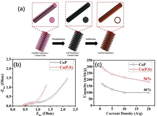
One way is to dope the faradic materials with heteroatoms, which can tune their electronic structure to facilitate the charge transfer process.[55] Taking the work of John Wang, et al. for an example,[56] their group synthesized a kind of sulfur-doped cobalt phosphide nanotube arrays through combining the hydrothermal method, and thermal-treatment method, schematically shown in Figure 9a. The impedance spectra have been
- 25 -
used to analyze the energy storage process and the result proves that the electron-conductivity of the material has been improved after doping sulfur inside (Figure 9b). Compared with that of pristine CoP, the sulfur-doped CoP gives a smaller x-intercept point in the high-frequency region and a smaller semi-circle in the mid-high frequency region, indicative of the lower internal-resistance and charge transfer resistance, respectively. The better conductivity can finally achieve an improvement in terms of the energy storage performance. As shown in Figure 9c, the sulfur-doped CoP can
deliver a capacity of ~300 mAh g-1 at a current density of 1 A g-1 and remain 56% (156
mAh g-1) at a high current density of 20 A g-1. This energy storage performance is much
better than that of the pristine CoP electrode——175 mAh g-1 at the current density of
1 A g-1 and 46% capacity retention at the high current density of 20 A g-1. Not just
limited to this example, tremendous studies have proved that the heteroatoms doping strategy is an effective tool to enhance the energy storage performance by increasing the conductivity of the faradic materials.[57–59]
Figure 9. (a) Schematic illustration for the fabrication of sulfur doped CoP nanotube arrays on carbon cloth; (b) Impedance spectra of sulfur doped CoP and pristine CoP; (c) the rate performance difference between the sulfur-doped CoP and pristine CoP
- 26 -
Compositing faradic materials with other highly conductive materials (e.g., carbon-based materials or metals) can also alleviate the poor conductivity issue of the pure faradic materials. The difficulties of this approach are to optimize the ratio and the structure when configuring the composites. High ratio of the faradic materials will cause the electron conduction problem, but a high ratio of the conductive reagents, in turn, will lead to a loss of the capacity. Besides, the rational structure design of the composites is also important to make sure the efficient electron transfer throughout the entire interior of materials. For instance, Timothy S. Fisher et al. synthesized a graphene petal foam by chemical evaporation method and then electrodeposited Ni–Co hydroxide nanopetals on the surface of the foam to obtain the graphene petal foam/Ni– Co hydroxide nanopetals composites (GPF/NCHPs),[60] shown in Figure 10a. By controlling the electrodeposition time, they can receive a series of samples with different ratio of contents (longer deposition time will result in a higher proportion of the Ni-Co hydroxide). The SEM images of GPF/NCHPs, given in Figure 10b, reveal that the ultrathin graphene sheets with the hollow structure are interconnected, playing the electron-conduction role in the composite, and surface distributed Ni–Co hydroxide nanopetals act as the main active sites to store the energy, which should be very easy to accept/donate electrons from/to the graphene foam. This type of structure should be very favorable in the view of the energy storage. But, as discussed above, the ratio between the faradic materials and the conductive materials is crucial, and excessive loading of faradic materials will not be helpful to the energy storage performance. As shown in Figure 10c, if the deposition time longer than 3 min, the loading amount of Ni–Co hydroxide nanopetals getting higher, the rate performance of the composite gets worse and the capacities are even less than the sample with deposition time of 3 min at
- 27 -
Figure 10 (a) Schematic illustration for the structure of the graphene petal foam/Ni–Co hydroxide nanopetals (GPF/NCHPs); (b) SEM images of GPF/NCHP with different magnifications; (c) Rate performance of the GPF/NCHPs with different ratio of the Ni– Co hydroxide nanopetals (longer deposition time means the higher proportion of the Ni–Co hydroxide nanopetals).[60]
1.6.2 Improving the ions conductivity of faradic materials
Besides the electron conductivity issue, the ions conductivity may also restrict the performance of the faradic materials. As well known, the counter ions compensation processes that neutralize the charge change of redox centers are indispensable to complete the faradic reactions and always become the rate-determine step. Therefore, rationally constructing ions diffusion channels to reduce the ions diffusion resistance is necessary to improve the performance (especially the rate performance) of faradic
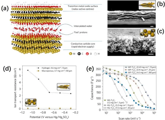
materials. In recent years, Yury Gogotsi et al., analyzed the relationship between
structure and ions diffusion resistance through a single variable control experiment via preparing two titanium carbide electrodes (the chemical structure given in Figure 11a) with different structures.[61] From the SEM cross-section views of the two electrodes (Figure 11b&c), one electrode shows the compact layer-by-layer structure (labelled as
- 28 -
the hydrogel-electrode or HG-Ti3C2), but the other is highly porous (labelled as the
Macroporous-electrode or MP-Ti3C2). In spite of the same chemical properties of the
two electrodes, their energy storage behaviors are significantly different due to the
different structure. Compared with that of HG-Ti3C2, the highly porous structure of
MP-Ti3C2 is able to provide a much shorter ions diffusion pathway when the counterions
diffuse inside the electrode during the redox reaction (illustrated in the insertions of
Figure 11b&c). Therefore, the ions diffusion resistance inside the MP-Ti3C2 electrode
is much smaller than that in HG-Ti3C2,even if the electrode thickness of MP-Ti3C2
electrode is ten times thicker than HG-Ti3C2. (See Figure 11d) Because of that, the
energy storage behaviors of the two different electrodes are tested in 1M H2SO4 by
cycling voltammetry. As a result, despite the similar capacities at low scan rates, much
better rate performance can be observed for MP-Ti3C2 electrode (Figure 11e), benefited
from the much smaller ions diffusion resistance.
Figure 11 (a) Chemical structure of titanium carbide; the cross-section SEM images:
(b)hydrogel-electrode (HG-Ti3C2) and (c) macroporous-electrode (MP- Ti3C2); (d) Ions
diffusion resistance of HG-Ti3C2 and MP- Ti3C2; (e) Rate performance comparison
- 29 -
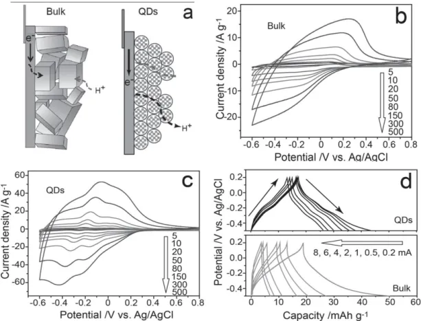
Besides, constructing appropriate pore structures/reducing the size of material to increase the surface-volume ratio is also an efficient way to improve the ions diffusion during the redox reaction. There are two ion diffusion stages for the energy storage processes of faradic materials. The first stage is the counterions in electrolyte diffuse onto the interface of the faradic materials, and resistance of this process depends on the porous structure, as we discussed earlier. After this, the counter ions would further insert into the solid phase because the active sites in the bulk phase, especially in the near-surface region, also take part into the redox reaction. However, the ions diffusion inside the solid phase is orders smaller than that in liquid phase.[62,63] Therefore, minimizing the size of the materials to shorten the diffusion length inside the solid phase will be also helpful to reduce the ions diffusion resistance so that can improve the energy storage performance of the faradic materials. For example, Fengxia Geng et al. synthesized two different sizes of tungsten oxide (one with a diameter of ca.3 nm, labeled as Bulk; the other one with a diameter of ca. 1.5 nm, labeled as QDs) and further compared their energy storage behaviors.[64] Compared with Bulk electrode, The QDs electrode owns much faster ions diffusion, illustrated in Figure 12a, and much smaller peak-to-peak separations can be observed for QDs electrode, see Figure 12b&c, indicative of the more reversible redox reactions due to the reduced ions-diffusion distance in solid phase. The charge-discharge curves of the two electrodes are given in
Figure 12d, and the two electrodes show very similar capacity at a low current of 0.2
mA. However, with the charge-discharge currents gradually increase, the capacity fades very fast for the Bulk electrode in comparison to that of QDs electrode. This phenomenon indicates the slow ions diffusion in solid-phase may become the rate-determine step at high currents/short charge-discharge time, and reducing the ions diffusion length in solid-phase is an effective approach to improve the performance of faradic materials.
- 30 -
Figure 12 (a) Illustration of the ions transfer processes for the Bulk electrode and QDs electrode during the redox reaction; the cyclic voltammetry responses at different scan
rates: (b) Bulk electrode and (c) QDs electrode; (d) Charge-discharge difference
between QDs electrode and Bulk electrode.
1.7 Electron-hopping as the mechanism to achieve redox reactions
From the discussion above, we can see that the rate performance of traditional faradic materials depends on two aspects: electron movement rate inside the faradic materials and counterions diffusion rate inside the solid phase. However, the intrinsic electronic structure of most of them are close to isolator that is not favorable for the electrons to move and ions diffusion inside solid phase is very slow (the ions diffusion coefficient
inside solid phase is ca.10-9 cm2 s-1) [62]. As discussed above, many strategies have
been developed to improve these two aspects of the faradic materials, so that to enhance their energy storage performances. Nevertheless, think of it in another way, whether we can find a new redox manner so that to accelerate the ions/charges transport at same
- 31 - time.
Back to the 1960s, the electron-hopping phenomenon was discovered, where the electrons can directly transport among active centers without physical connections,[65]
The surface-tethered electroactive molecules with flexible linkers can undergo “fast”
charge transfer reactions, as reported for self-assembled monolayers [66] or large
dendrimers.[67,68] In the following decades, many studies have been done to analyze
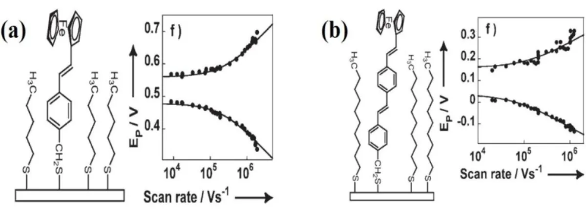
the electrons transfer behavior and found the distance between redox centers is a very important factor. For example, Christian Amatore et al. prepared two monolayer systems to study the electron-hopping process, and both molecules contain one terminal ferrocene molecule but with different length of hydrocarbon, as shown in Figure
13a&b.[69] By analyzing the peak separations during the cyclic voltammetry of the two
systems at different scan rates, they found the redox kinetics could reach ca. 106 s-1 for
both systems, which is much faster than that of traditional faradic materials. Besides, the monolayer system with shorter hydrocarbon chain would deliver faster kinetic due
to the reduced distance for the ferrocene center. (Redox kinetic constant is 4×10⁶ s-1 for
the system in Figure 13a, and 2×10⁶ s-1 for the system in Figure 13b) Compared with
conventional redox manner, the electron-hopping mechanism can permit a much higher reaction rate due to the following two reasons. 1) the electron transfer speed is fast, which is not limited to the conductivity of the faradic materials but determined by the transfer speed of oxidation/reduction state of redox centers. 2) the fast counterions
compensation rate because the ions diffusion rate in electrolyte is normally ca.104
orders higher than in solid phase.[62,63] Despite the great advantage of electron-hopping mechanism, however, as far as we knew, there is no relative work that introduces this mechanism to the energy storage field.
- 32 -
Figure 13. Evolution of the redox peaks separation during cyclic voltammetry at different scan rates: (a) Ferrocene derivate bearing one styrene unit; (b) Ferrocene derivate bearing two styrene units.
1.8 The fabrication of ordered mesoporous silica-based materials and
their applications
The synthesis of ordered mesoporous silica materials started from last century,[70] and attracted broad research interest from scientists in the flowing years due to their intriguing characteristics such as large surface area, easy to control morphology and achieve the surface functionalization, high chemical stability and biocompatibility and low cost.[71] A series of novel mesoporous silica materials have been synthesized via using the surfactant micelle as the soft template including the family of SBA (SBA-1, SBA-6, SBA-15 and SBA-16 etc.),[72,73] FDU (FDU-1 and FDU-12 etc.),[74,75] MSU (MSU-G, MSU-H, and MSU-V etc.),[76,77] and KIT (KIT-1 and KIT-6).[78,79] They show incomparable advantages in many fields such as adsorption,[80]
separation,[81] catalysis,[82] sensors,[83] biomedicine,[84] environmental
protection,[85] and assisting synthesis of nanomaterials.[86] There is an important branch in the family of silica materials, namely self-assembled mesostructured silica films, which are expected to facilitate materials integration in devices (including the miniaturized ones) for target applications. The present work is based on redox active functionalized silica films and there are two main methods to prepare such films: 1)
- 33 -
Evaporation-Induced Self-Assembly method (EISA) method; 2) Electrochemically Assisted Self-Assembly (EASA) method.
1.8.1 Preparing ordered mesoporous silica film with EISA method
At the very beginning, the ordered mesoporous silica thin films were generated on the underlying substrates by the epitaxial growth process at gas-liquid interfaces,[87] liquid-solid interfaces,[88] or liquid-liquid interfaces.[89] However, the film fabrication process with these epitaxial growth methods always suffer from long-time deposition and unevenness problem etc.[90] Jeffrey Brinker et al. firstly proposed the EISA method,[91] which can significantly accelerate the film fabrication process. To be specific, first, a starting solution composed of ethanol, water, surfactant, and silane precursor is prepared, where the concentration of the surfactant does not reach the critical micelle concentration. Then, dip a substrate inside the solution and pull it out soon afterwards. The evaporation of the solvent will let the surfactant reach the critical micelle concentration to form a hexagonal, cubic or layered micelle, and the polycondensation of silane will occur surrounding the micelle generating the silica film on the surface of the substrate. The formation mechanism of silica film is illustrated in
Figure 14a. From the TEM analysis, the structure of silica film is highly ordered with
parallelly aligned cubic channels. (Cross-section view in Figure 14b and top-view in
Figure 14c). A series of silica films with different channel structure can be easily
prepared by changing the species/concentration of the surfactant via this approach. The discovery of this versatile method has prompted a lot with respect to the fabrication of ordered mesoporous silica film.
- 34 -
Figure 14. (a) Silica film formation mechanism by EISA method; The TEM images of
the film: (b) cross-section view; (c) top-view.[91]
1.8.2 Preparing ordered mesoporous silica film with EASA method
Despite the great superiority of the EISA method, there are still some drawbacks due to
the nature of the assembly process. In particular, the orientationof the mesochannels of
silica films prepared with EISA method is always parallel to the substrate, which may hinder the mass transport inside the film.[92] Therefore, our group first reported an EASA method in 2007 to generate the vertically aligned mesoporous silica film on the conductive substrate.[93] The silica film can be easily prepared by applying a negative potential on the electrode that is immersed in the water/ethanol precursor solution containing certain amount of a cationic surfactant (CTAB) and the hydrolyzed silane.
The applied negative potential will induce the self-assembling of the CTA+ micelle
orthogonal to the substrate and meanwhile generate hydroxide ions to catalyzing the polycondensation of hydrolyzed silane precursors around the surfactant on the surface