Publisher’s version / Version de l'éditeur:
ASHRAE Journal, 14, 8, pp. 46-54, 1972-09-01
READ THESE TERMS AND CONDITIONS CAREFULLY BEFORE USING THIS WEBSITE. https://nrc-publications.canada.ca/eng/copyright
Vous avez des questions? Nous pouvons vous aider. Pour communiquer directement avec un auteur, consultez la première page de la revue dans laquelle son article a été publié afin de trouver ses coordonnées. Si vous n’arrivez pas à les repérer, communiquez avec nous à [email protected].
Questions? Contact the NRC Publications Archive team at
[email protected]. If you wish to email the authors directly, please see the first page of the publication for their contact information.
NRC Publications Archive
Archives des publications du CNRC
This publication could be one of several versions: author’s original, accepted manuscript or the publisher’s version. / La version de cette publication peut être l’une des suivantes : la version prépublication de l’auteur, la version acceptée du manuscrit ou la version de l’éditeur.
Access and use of this website and the material on it are subject to the Terms and Conditions set forth at
Computer analysis of smoke control with building air handling systems
Tamura, G. T.
https://publications-cnrc.canada.ca/fra/droits
L’accès à ce site Web et l’utilisation de son contenu sont assujettis aux conditions présentées dans le site LISEZ CES CONDITIONS ATTENTIVEMENT AVANT D’UTILISER CE SITE WEB.
NRC Publications Record / Notice d'Archives des publications de CNRC:
https://nrc-publications.canada.ca/eng/view/object/?id=15149f74-fd01-4073-99ec-5778cceb3b89 https://publications-cnrc.canada.ca/fra/voir/objet/?id=15149f74-fd01-4073-99ec-5778cceb3b89NATIONAL RESEARCH COUNCIL OF CANADA CONSEIL NATIONAL DE RECHERCHES D U CANADA
Computer Analysis of Smoke Control
with Building Air Handling Systems
by G.T. Tamura
Reprinted from ASH RAE Journal Vol. 14, No. 8, August 1972
p. 46-54
By permission o f the American Society of Heating, Refrigerating and Air-Conditioning Engineers, Inc.
Research Paper No. 534 of the
Division of Building Research
OTTAWA September, 1972
ANALYSE INFORMATIOUE DE L A REGULATION DE L A FUMEE DANS UN EDIFICE AU MOYEN
DY SYSTEME DE DISTRIBUTION DE L'AIR
Au moyen d'un modele mathematique, I'auteur etudie le r6le que joue le systeme central de distribution de I'air dans la regulation du mouvement de la fumee au cours d'un incendie. L'Ltude comporte le calcul informatique des mouvements de I'air et de la fumee et des taux d'accumulation de la fumee dans un edifice hypothetique. On examine diffkt-entes possibilites: la fermeture du systeme de distribution de I'air, puis le fonctionnement des systemes d'insufflation et d'aspiration ensemble et separement. On evalue les resultats selon les conditions qui ont cours en etL d'une part et en hiver de l'autre.
COMPUTER ANALYSIS
OF SMOKE CONTROL
WITH BUILDING AIR HANDLING SYSTEMS
GEORGE T. TAMURA Member A S H R A E
Experiments involving actual fires in commercial-type buildings are at best difficult and costly. Proposed here is a computer- oriented experimental procedure that employs a mathematical model which can yield data on smoke movement and control requirements on a hypothetical basis.
C
ENTRAL air handling systems are commonly used to distribute conditioned air within a building. The net- work of ducts necessary for the distribution of air intercon- nects various spaces of a building. In the event of a fire, the air handling system can, therefore, act as a vehicle for the spread of fire and smoke far beyond the origin of fire.This potential for fire and smoke spread is recognized in National Fire Protection Assn ( N F P A ) Standard 90A, for the Installation of Air-Conditioning & Ventilation Sys- t e m ~ . ~ T o maintain integrity of a fire-resistive separation, NFPA 90A specifies fire dampers in air ducts where they penetrate such a separation, T o prevent recirculation of smoke by the air handling system, it specifies provisions for a fan shutdown when excessive smoke is sensed inside an air duct. The Standard also recognizes the possibility of us- ing the air handling system as a means of smoke removal and guidelines are set forth to assist designers in providing such a system.
Information on the behavior of air handling systems, relative to smoke movement, whether they are passive or active during a fire, can best be obtained with fire tests in buildings. However, such tests are difficult to carry out. With a mathematical model, such as the one described in this article, a fire in a floor space can be simulated, and the resultant smoke flow pattern and rate of smoke build-up within a building can be computed. This article describes the basis for a mathematical model used to study the effect of an air handling system on smoke movement and presents results of this study.
MODEL BUILDING
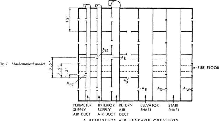
The hypothetical building selected for study is essentially the same as the one described in a previous paper by the author.' It is 20 stories high with a plan dimension of 120 by 120 ft and a floor height of 12 ft. An open floor plan building was assumed, with five vertical shafts representing
G.T. Tcrmura is Research Oficer, Bllildir~g Services Section, Divi- sion of B~lilditzg Reseorclz, Natiorlal Research Courlcil of Carzcrda, Ottaiva, O~rt., Canada.
elevator shafts, stair shafts, perimeter and interior supply air ducts and return air ducts. The four-story model (Fig. 1 ) illustrates all major components for the building.
Leakage areas in major separations were lumped to- gether and represented by equivalent orifice areas. T h e equivalent orifice areas used in this study were based on results of tests made on four modern multi-story build- i n g s . ' , T h e y are 2.5 sq ft per story (total) for the outside walls (A,,.), 4.5 sq f t per story (total) for four elevator shafts (A,), 0.5 sq ft per story (total) for two stair shafts (A,), and 3.7 sq f t (total) for the floor construction ( A , ) . Openings in the branch perimeter and interior supply air ducts (A,,, A,,) are 7.0 sq ft per story and in the return air ducts ( A , ) , 14.0 sq ft per story. These areas are based on an air velocity of about 1000 fpm and on an air circula- tion rate of 5 air changes/hr for each history. Provision was made in the model to simulate the supply of air into the main supply ducts and the exhaust of air from the main return duct equivalent to 5 air changes/hr for the building as a whole. Friction losses inside these ducts were not taken into account in the model.
All openings are located at mid-height for every story except the one where the fire is located. The fire zone is treated as a combination of four stories 3 ft in height with large openings in the intervening floors. In this way, open- ings in the vertical separations can be located at four levels for this story. Leakage openings in the stair shafts, elevator shafts and outside walls were divided and located at 1.5 and 7.5 ft above floor level. Openings in the perimeter sup- ply branch air ducts were located 1.5 ft above floor level and those in the interior supply and return branch air ducts were located 10.5 ft above floor level.
The pattern of smoke migration for a @en fire condi- tion was obtained in two steps. The first step involves the calculation of the pressure differential and the mass flow rate across each separation. This requires setting up a mass flow balance equation for each compartment inside the building. The following equation was used to represent the rate of mass flow through an opening:
where
w = mass flow
C = proportionality constant
A = orifice area
Fig. I M a ~ h e m a ~ i c n l model
.FIRE FLOOR
PERIMETER INTERIOR LRETURN ELEVATOR STAIR
SUPPLY SUPPLY AIR SHAFT SHAFT AIR DUCT AIR DUCT DUCT
A R E P R E S E N T S A I R L E A K A G E O P E N I N G S
AP = pressure difference across orifice n = flow exponent
T h e value of the flow exponent for leakage paths can vary from % f o r turbulent flow to 1 for laminar flow. F o r the hypothetical building, a flow exponent of '/2 was as-
sumed for all supply and return openings, and for all leak- age openings in the walls of the shafts and in the floor construction. A flow exponent of % was assumed for leak- age openings in the exterior walls. T h e equivalent orifice area of 2.5 sq ft per floor for the exterior wall given above was calculated from test data at 0.3 in. of water pressure difference, assuming a flow exponent of %. This leakage area was, therefore, modified to 3.0 sq f t per floor to give the same flow rate at this pressure difference with a flow exponent of 7 3 .
Because the mass flow balance equations are non-lin- ear, an iterative technique was used t o solve for the pres- sure differentials and mass flow rates across all separations of the building.
T h e second step involves the calculation of transient smoke migration using the values of mass flow rates ob- tained from the first step. T h e equation f o r each compart- ment is:
dci
"
~ i v i
-
=C
wjicjd t j-1 where
wji = flow rate from space j into space i ; when this is negative, cj is replaced by ci
p = air density
V = volume of compartment
t = time
This equation assumes instantaneous and complete mixing of smoke with air in a compartment. Each vertical shaft is treated as if it were divided into separate compart-
ments of one floor height. The volume assumed for each fictitious compartment in the vertical shafts was 3480 cu f t for the elevator shafts, 2400 cu ft for the stair shafts, 5 5 0 cu ft for the return air duct, and 275 cu f t for each supply duct. T h e system of simultaneous differential equations was solved using a numerical method t o obtain the values of smoke concentration in each compartment at intervals of 0.05 min.
CASES INVESTIGATED
The following cases were investigated for the hypothetical 20-story building: ( 1 ) no vertical air ducts; ( 2 ) with verti- cal air ducts-air handling systems shut down, n o branth air duct damper; ( 3 ) branch air ducts dampered on fire floor-air handling system shut down; ( 4 ) supply and re- turn air systems operating ( 5 ) return air system operating with supply air system shut down; and ( 6 ) supply air sys- tem operating with return air system shut down.
F o r the above cases, a fire was assumed to be located on the second story, where the temperature was assumed to be 1000 F. A temperature of 7 5 F was assumed in the re- maining parts of the building. The temperatures, and hence the resultant air and smoke flow rates, were assumed to be constant with time. Initially, the effect of thermal expansion of gases during the development phase of the fire was not considered in the assumed conditions. Smoke concentration on the fire floor was assumed to be 1.0, and zero in all other floors. Smoke concentration in the fire floor was also assumed to be constant with time. T h e value of 1.0 is in- tended to represent maximum smoke concentration in terms of optical density per ft of 1.2 to 2.4 likely t o be en- countered during a severe fire. 1 % of these values can be considered as a limiting value for safety of occupant^.^
F o r most cases investigated, it was assumed that dur- ing the fire. exterior walls remained intact and the doors of elevator and stair shafts were closed at all stories.
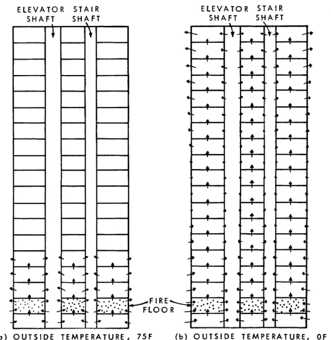
E L E V A T O R S T A I R S H A F T S H A F T E L E V A T O R S T A I R S H A F T S H A F T O U T S I D E T E M P E R A T U R E , / F I R E F L O O
75F
( b ) O U T S I D E T E M P E R A T U R E ,Fig. 2 Slrloke flow patterrl for 20-story buiidir~g 1vil11 110 vertical nir rlztcts: Case I
RESULTS & DISCUSSION
For cases 1, 2 and 3, the air handling systems are assumed to be shut down during the fire. For cases 4, 5 and 6, some or all of the air handling systems are in operation. Smoke concentration patterns at the end of one hour for all of the cases for outdoor temperatures of 75 and 0 F are calcu- lated and compared.
Case 1-No Vertical Air Ducts: This case was included to provide a basis for judging the other cases. It can be con- sidered as a building with no central air handling system but with a separate air system for each story.
With outdoor temperature at 75 F, there is no stack action associated with building heating or cooling and, hence, smoke movement is caused by the local stack action due to the temperature of the fire. Fig. 2a illustrates resul- tant air flow pattern for this case. Air flows into the fire
zone through lower openings in the outside walls and the walls of the vertical shafts, and smoke flows out through the upper openings of these walls. Also, air flows into the fire zone from the space below and smoke flows out into the story above. The neutral pressure plane of the fire zone relative to the elevator and stair shafts is located 3.8 ft above floor level. The flow pattern induced by the fire for the stories above and below the fire zone is also shown in Fig. 2a.
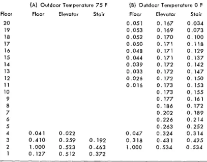
Table IA indicates the smoke concentration pattern at the end of 1 hr. Smoke concentration above the critical level ( 1 % of the smoke concentration in the fire floor) is exceeded in stories 1 to 4, in the elevator shafts below the 5th floor level, and in the stair shafts below the 4th floor level. If the effect of thermal expansion of gases in the fire zone is considered, smoke concentrations in the building
Table I. Smoke Concentration for 20-Story Building: Case 1-No Vertical A i r Ducts Floor 20 19 18 17 16 15 14 13 12 11 10 9 8 7 6 5 4 3 2 1
(A) Outdoor Temperature 7 5 F (B) Outdoor Temperature 0 F
Floor Elevator Stair Floor Elevator Stair
0 . 0 5 1 0 . 1 6 7 0 . 0 3 4 0 . 0 5 3 0 . 1 6 9 0 . 0 7 3 0 . 0 5 2 0 . 1 7 0 0 . 1 0 0 0 . 0 5 0 0 . 1 7 1 0 . 1 1 8 0 . 0 4 8 0 . 1 7 1 0 . 1 2 9 0 . 0 4 4 0 . 1 7 1 0 . 1 3 7 0 . 0 3 9 0 . 1 7 2 0 . 1 4 2 0 . 0 3 3 0 . 1 7 2 0 . 1 4 7 0 . 0 2 6 0 . 1 7 2 0 . 1 5 0 0 . 0 1 6 0 . 1 7 3 0 . 1 5 3 0 . 1 7 3 0 . 1 5 5 0 . 1 7 7 0 . 1 6 1 0 . 1 8 6 0 . 1 7 2 0 . 2 0 2 0 . 1 8 9 0 . 2 2 6 0 . 2 1 4 0 . 2 6 3 0 . 2 5 2 0 . 0 4 1 0 . 0 2 2 0 . 0 4 7 0 . 3 2 4 0 . 3 1 4 0 . 4 1 0 0 . 2 5 9 0 . 1 9 2 0 . 3 1 8 0 . 4 3 1 0 . 4 2 5 1.000 0 . 5 2 3 0 . 4 6 3 1.000 0 . 5 3 4 0 . 5 3 4 0 . 1 2 7 0 . 5 1 2 0 . 3 7 2
N o t e s : F r t u on > ~ L O I I ~ floor; smoke concetirrslton o n sucorid floor . 1.000: ooly lllosf! vzililcs grcalf!r lhon or ctlual 10 0.010 ale shown. smoke concentration a t lhr: i:nrl of 1 h r .
can be expected to be much higher than those inTable IA. Fig. 2b illustrates the flow pattern caused both by the temperature effect of fire and by stack action with outdoor temperature of 0 F. The neutral plane of the building rela- tive to outside is located at mid-height of the building with air flow into the building below the neutral plane and air flow out of the building above it. Similarly, air flows into the vertical shafts from the surrounding spaces below mid- height and out of the vertical shafts into the surrounding spaces in the top half of the building. The direction of flow through openings in the floor construction is upward. The effect of the building stack action is to increase the pressure on the fire floor equivalent to shifting the neutral plane of the fire zone to the floor level of that zone. T h e pressures in the fire compartment thus are higher than those in the shafts causing smoke to flow from the fire compartment into the vertical shafts through both the lower and upper openings.
Table IB illustrates the smoke concentration pattern at the end of 1 hr with outdoor temperature of 0 F. With the exception of the first story and stories 5 to 10, all areas are above the critical level of smoke concentration. With out- door temperature of 3 5 F, smoke concentrations in the up- per stories (12 to 2 0 ) are above the critical level and are approximately two-thirds of those shown in Table IB. Be- cause of the flow pattern induced by building stack action, smoke flow is increased into the vertical shafts and the up- per floors from a fire floor located below mid-height. On the other hand, if the fire is located in the top half of the building, smoke flow into the vertical shafts caused by the temperature effect of the fire is decreased due t o building stack action.
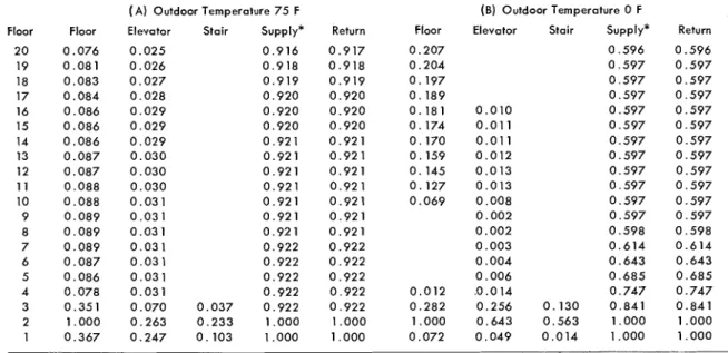
Case 2-With Vertical Air Ducts-Air Handling Systems Shut Down, N o Branch Air Duct Damper: Vertical supply and return air ducts of a central air handling system were incorporated into the computer sin~ulation of the 20-story building. None of the openings in the branch air ducts were
dampered. T h e location of the air duct openings near the top of the fire compartment as shown in Fig. 1 increased the level of the neutral plane relative to elevator and stair shafts from 3.8 ft (Case 1 ) to 6.6 ft above the floor level f o r outdoor temperature of 7 5 F and from the floor level (Case 1 ) to 5.2 ft above the floor level f o r outdoor temper- ature of 0 F. This resulted in a decrease in the rates of smoke flow into the elevator and stair shafts from the fire compartment compared with the previous case.
Table IIA shows the smoke concentration pattern a t the end of 1 hr for outdoor temperature of 7 5 F. All spaces are above the critical level of smoke concentration except in the stair shafts where the smoke concentration levels are below t h e critical level for all spaces higher than the third story. Although the rate of smoke flow from the fire com- partment into the elevator shafts is lower compared t o Case 1, smoke flow from the floor spaces into the elevator shafts resulted in higher smoke concentrations in these shafts compared to Case 1 with no vertical air ducts. Smoke build-up in the floor spaces for Case 2 was caused by smoke transfer through both the interior supply and return air ducts. As the branch duct of the perimeter supply sys- tem is located near the floor level, it did not contribute to the smoke contamination of the upper stories.
Table IIB shows that, for outdoor temperature of 0 F , smoke levels in the stories are well above the critical level except f o r stories 5 to 9. Smoke levels in the upper stories are approximately four times higher than they were in the case with no vertical air ducts. Smoke concentrations in both the interior supply and return air ducts are well above the critical value at all locations. Smoke concentrations in the elevator and stair shafts are, however, significantly lower than what they were in Case 1. With building stack action, the direction of smoke flow is from the elevator and stair shafts into the upper stories so that smoke in the up- per stories did not contribute t o the contamination of these shafts as was the case with outdoor temperature of 7 5 F (Case 2 ) . These results indicate that vertical main air ducts
Table II. Smoke Concentration for 20-Story Building: Case 2-Air Handling Systems Shut Down, No Air Duct Dampers
Floor 2 0 19 18 17 16 15 14 13 12 1 1 10 9 8 7 6 5 4 3 2 1 Floor 0.076 0.081 0.083 0.084 0.086 0.086 0.086 0.087 0.087 0.088 0.088 0.089 0.089 0.089 0.087 0.086 0.078 0.351 1.000 0.367 ( A ) Outdoor Temperature 75 F
Elevator Stair Supply*
0.025 0.916 0.026 0.918 0.027 0.919 0.028 0.920 0.029 0.920 0.029 0.920 0.029 0.921 0.030 0.921 0.030 0.921 0.030 0.921 0.031 0.921 0.031 0.921 0.031 0.921 0.031 0.922 0.031 0.922 0.031 0.922 0.031 0.922 0.070 0.037 0.922 0.263 0.233 1.000 0.247 0.103 1.000
' ln~c!uor SLIIIJIIY d u c l . Pc!lll~ll!lr!l supply d u c t n o t shown.
Noles: F l r c o n rcconrl I l o o ! , snmke c o ~ ~ c c n t r a l ~ o n 011 si!co17cl ll o o r cnrl of 1 hr.
(B) Outdoor Temperature 0 F
Return Floor Elevator Stair Supply* Return
0.917 0.207 0.596 0.596 0.918 0.204 0.597 0.597 0.919 0.197 0.597 0.597 0.920 0.189 0.597 0.597 0.920 0.181 0.010 0.597 0.597 0.920 0.174 0.011 0.597 0.597 0.921 0.170 0.011 0.597 0.597 0.921 0.159 0.012 0.597 0.597 0.921 0. 145 0.013 0.597 0.597 0.92 1 0.127 0.013 0.597 0.597 0.921 0.069 0.008 0.597 0.597 0.921 0.002 0.597 0.597 0.921 0.002 0.598 0.598 0.922 0.003 0.614 0.614 0.922 0.004 0.643 0.643 0.922 0.006 0.685 0.685 0.922 0.012 .0.014 0.747 0.747 0.922 0.282 0.256 0.130 0.841 0.841 1.000 1.000 0.643 0.563 1.000 1.000 1.000 0.072 0.049 0.014 1.000 1.000
1.000; < ~ n l y ~ h o r i : ualues < j ~ c a i c l 1li.10 o l r,<lui~l t o 0 . 0 1 0 ;mr: hewn. sfnokc concenlr.lilon ;,I ih,:
with n o dampers and with the fans shut down can contrib- ute greatly t o the smoke contamination of upper stories.
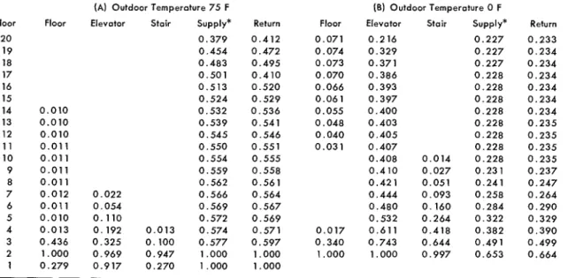
Case 3-Branch Air Ducts Dampered at the Fire Zone- Air Handling Systems Shut Down: This case is similar to
the previous one except that the interior supply and return branch air ducts, both located near the top of the fire com- partment, are obstructed by a damper at the fire zone. It was assumed that the leakage area of a closed damper is 1 5 % of the duct open area. Table I11 gives the smoke con- centration pattern at the end of 1 h r for outdoor tempera- tures of 75 and 0 F. Comparison of smoke concentration values with those of Table I1 for the building with vertical air ducts but with no dampers shows that with the air ducts dampered, smoke concentration values in the floor spaces are significantly lower for both cases at the end of 1 hr but are higher than those of Table I for the building with no vertical air ducts. With a damper leakage area that is 1 0 % of the duct open area, smoke concentrations in the upper stories were similar to those of Table I. T h e net effect of reducing the opening of the branch air ducts at the fire zone to 1 0 % of the open area is that the vertical air ducts are no longer significant relative to other vertical shafts in transferring smoke t o upper stories.
In all the cases examined so far, it has been assumed that the exterior walls of the fire compartment are intact during the entire fire. The results of these cases would be applicable for windowless buildings where this condition is likely t o exist. T h e effect of a large opening, a broken win- dow f o r example, is that the pressure in the fire compart- ment would be equalized with outside pressure at the same level. Smoke concentration levels in the building can be higher than those illustrated for the three cases if there are any large openings in the windward wall o r if there are large openings in the exterior walls of a fire floor located below the neutral plane of a building during cold weather. F o r example, for this case with a 4 0 sq ft opening in the
exterior walls at the fire zone and for a n outdoor tenipera- ture of 0 F, smoke concentrations are approximately twice those shown in Table IIIB. All stories except the fifth floor are above the critical level of smoke concentration. As smoke flow from the fire compartment into the branch duct of the perimeter supply can be expected under this condi- tion, this branch duct was also dampered.
Case 4-Supply & Return Air Systems Operating: In all
cases examined so far the air handling systems were off. In Case 4 both the supply and return air systems are operating during the fire. T o prevent recirculation of smoke through the air handling systems, the outside dampers are posi- tioned so that the supply air system takes in 1 0 0 % outdoor air and the return air system exhausts all return air t o the outdoors. Flow capacities of the air handling systems for the hypothetical building are 288,000 cfm for both the sup- ply and return air systems to give an air circulation rate of 5 air changes/hr. All danlpers in the supply and return air ducts are in the open position.
A ventilation-controlled fire is postulated so that with an increase in exhaust rate and, hence, an increase in the rate of air flow into the fire floor, there is a corresponding increase in the rate of combustion and smoke production in the fire zone. Therefore, although smoke is exhausted from the fire zone through the return air system t o outside, it is assumed that the smoke concentration in the fire floor re- mains constant during the fire.
T h e operation of the air handling systems during a fire affects the smoke concentration pattern in a buildin, 0 ' in sev-
eral ways. ( 1 ) It provides diluent air t o all the floor spaces, thus reducing the rate of smoke build-up in these areas. ( 2 ) Because of high temperature in the fire zone, the rate of supply and exhaust in this zone may differ from those on other stories. ( 3 ) Air ducts no longer act as a passageway for smoke t o travel t o upper stories. F o r the modcl build- ing, air supply and exhaust rates o n each story (14,600
Floor 20 19 18 17 16 15 14 13 12 11 10 9 8 7 6 5 4 3 2 1
Table Ill. Smoke Concentration for PO-Story Building: Case 3-Branch Air Ducts Dampered on Fire Floor- Air Handling Systems Shut Down (Leakage Area of Closed Damper-1 5% o f Duct Open Area)
Floor 0.010 0.010 0.010 0.01 1 0.01 1 0.011 0.01 1 0.012 0.01 1 0.010 0.013 0.436 1.000 0.279
(A) Outdoor Temperature 75 F Elevator Stair Supply* 0.379 0.454 0.483 0.501 0.513 0.524 0.532 0.539 0.545 0.550 0.554 0.559 0.562 0.022 0.566 0.054 0.569 0.110 0.572 0.192 0.013 0.574 0.325 0.100 0.577 0.969 0.947 1.000 0.917 0.270 1.000 Return 0.412 0.472 0.495 0.410 0.520 0.529 0.536 0.541 0.546 0.551 0.555 0.558 0.561 0.564 0.567 0.569 0.571 0.597 1 ,000 1.000 Floor 0.071 0.074 0.073 0.070 0.066 0.061 0.055 0.048 0.040 0.031 0.017 0.340 1.000 (B) Outdoor Temperature 0 F
Elevator Stair Supply*
0.216 0.227 0.329 0.227 0.371 0.227 0.386 0.228 0.393 0.228 0.397 0.228 0.400 0.228 0.403 0.228 0.405 0.228 0.407 0.228 0.408 0.014 0.228 0.410 0.027 0.231 0.421 0.051 0.241 0.444 0.093 0.258 0.480 0.160 0.284 0.532 0.264 0.322 0.611 0.418 0.382 0.743 0.644 0.491 1.000 0.997 0.653 Return 0.233 0.234 0.234 0.234 0.234 0.234 0.234 0.235 0.235 0.235 0.235 0.237 0.247 0.264 0.290 0.329 0.390 0.499 0.664
' I n l e r ~ o r sup(lly duct. Pur~rneter s v t l ~ ~ l y d u c t n o t shown. N o i c s - F l r c on ri:conl-I floor: rlnake conu,:ntl-at~or on riico,lcl f l o o r
cnd o f 1 hr.
1 000; o n l y tl\osc valu,:s (I,i!nter than or equal l o 0 . 0 1 0 ;lro shown, r t n o k c conct!nrraLion a i i h c
Table IV. Smoke Concentration f o r 20-Story Building: Case 4 ( A) Outdoor Temperature 75 F
Floor Floor Elevator Stair Supply Return
-Supply & Return Air Systems Operating, N o Dampers
(B) Outdoor Temperature 0 F
Floor Elevator Stair Supply Return
N o l e r Fctc on reconii I l a o r ; rrnoke c o n c e n t t a l l o n ah sct:onrl l l a o ~ 1 000; o n l y thc~ri! valrlr:s qrcillvr I h o n
or equal l o 0 . 0 1 0 a r e shown; r n l u k e c o t l c c n t , a t l o , i 2 1 the cmcl of 1 h r
c f m ) , except where the fire is, are balanced so that they do not affect the pressures in these'spaces. F o r the fire zone, however, because of the temperature effect of the fire, air supply rate is 12,600 cfm and air exhaust rate is 10,600 scfm resulting in a pressurization of the fire compartment by approximately 0.02 in. of water. T h e rate of smoke flow into stair and elevator shafts from the fire zone is greater, therefore, than when the air handling systems are not oper- ating.
Table IV shows the smoke concentration patterns for Case 4 at the end of 1 hr, for outdoor temperatures of 75 and 0 F . T h e smoke concentration levels indicated in Table
IV can be compared with those of Table 111 for the case of air handling systems not operating and with the branch air ducts dampered at the fire floor. F o r outdoor temperature of 75 F, with thc air handling systems operating, the num- ber of floors above the critical level of smoke concentration is reduced from 14 (Case 3 ) to 3. Because of the higher rate of smoke flow into elevator and stair shafts with the air handling system operating, the smoke concentration values in these shafts are higher than those with the air handling systems shut down.
With outdoor temperature of 0 F , the smoke concen- trations in the elevator shafts are substantially lower but
T a b l e V. Smoke Concentration f o r 20-Story Building: Case 5-Return A i r System O p e r a t i n g w i t h S u p p l y System Shut D o w n Floor 20 19 18 17 16 15 14 13 12 1 1 10 9 8 7 6 5 4 3 2 1
(A) Outdoor Temperature 75 F Floor Elevator Stair Supply*
0.096 0.120 0.128 0.132 0.135 0.136 0.138 0.139 0.139 0.140 0. 140 0.141 0.141 0.142 0. 142 0.015 0.142 0.039 0.142 0.170 0.159 0.074 0.170 1.000 0.766 0.734 0.797 0.075 0.756 0.337 0.796 Return 0.061 0.064 0.067 0.071 0.076 0.081 0.087 0.093 0.101 0.110 0.121 0. 135 0.152 0.173 0.203 0.243 0.305 0.407 0.529 0.075 ( 8) Outdoor Temperature 0 F Floor Elevator Stair Supply* 0.194 0.021 0. 194 0.044 0.194 0.071 0.195 0.097 0.195 0.121 0. 195 0.141 0.195 0.158 0.195 0.171 0.195 0.182 0. 195 0.190 0.195 0.196 0.195 0.204 0.199 0.216 0.208 0.234 0.013 0.222 0.260 0.033 0.245 0.301 0.081 0.283 0.164 0.391 0.197 0.368 1.000 1.000 1.000 1.000 0.033 0.852 0.167 1.000 Return 0.062 0.065 0.068 0.071 0.075 0.080 0.085 0.092 0.099 0.108 0.119 0.132 0.148 0.169 0.198 0.237 0.296 0.394 0.512 0.033 - - ~- - - - -~ - ~
' I n t e r l o r stlpply duct. Purimc!t~:r su(lp1y ~ l u c l no1 shown.
Notes- F l r c o n scconrl iloor: rlnokr? concr?rltr,l,ton o n secoorl floor 1.000, only lilosu v;ilu~:r grcotaf t11a1, or crlu;ll to 0.010 are shown: rrnok<: concen1r;lllan ;11 the
end o i 1 lhr.
are higher in the stair shafts when the air handling system is operating compared with Case 3. Also, smoke concentra- tions are much lower in the upper stories with the air han- dling systems operating. These results indicate that with the air handling system on, a significant reduction in smoke concentration is obtained in the floor spaces, but some in- crease can be expected in the elevator and stair shafts. As the smoke concentrations in the tables also represent dilu- tion ratios, temperatures in the return air duct can be esti- mated from these ratios although heat losses to the sur- roundings arc not taken into account.
If one envisaged a situation where, during a fire, the air handling systems were operating and the fire dampers were closed in the branch rcturn air ducts at thc fire floor, then the air supply rate would be much greater than the exhaust rate at the fire floor. T h e resultant pressurization of the fire zone (0.10 in. of water) would cause more contam- ination of elevator and stair shafts as well as throughout the other parts of the building.
If only the branch supply air ducts are dampered at the fire floor, the exhaust rate through the return air ducts would be grcater than the supply air rate, so that a suction pressure would result in the fire compartment. F o r t h e model building, the supply air rate for this condition is 2350 cfm and the exhaust air rate is 8500 scfm producing a suction pressure of approximately 0.06 in. of water. With outdoor temperature of 7 5 F , this suction pressure induced air into the fire zone through all openings in the fire com- partment enclosure preventing any smoke transfer from the fire zone into stair and elevator shafts and into upper stories. When the outdoor temperature was 0 F , this suction pressure was not sufficient to prevent smoke transfer into the story above the fire compartment, although smoke flow from the fire compartment into the elevator and stair shafts was prevented. At the end of 1 hr, only the story above the fire compartment exceeded the critical level of smoke con- centration. With a large opening in the exterior walls of the
fire zone, however, pressures in the fire zone can exceed those of adjacent spaces and smoke contamination of the building can then be expected. Because of the diluent air supplied by the air handling systems, smoke concentrations in the upper stories were approximately 1 2 % of those with the air handling systems shut down (Case 3, also with a large opening in the exterior walls) o r approximately twice those of Table IVB of Case 4, with stories 1 1 to 2 0 above the critical level of smoke contamination.
Case 5-Return Air System Operating with Supply Air System Shut Down: In this case, only the return air system is operating and the supply branch ducts are obstructed by dampers at the fire zone. With air exhausted to outside through the return air system, suction is created within the building; the amount of suction produced depends o n the rate of air exhaust and the degree of air tightness of the exterior enclosure of the building. F o r the hypothetical 20- story building with an air exhaust rate of 5 air changes/hr, the resulting suction pressure is approximately 5 in. of wa- ter. This suction pressure and the exhaust rates are likely t o be much lower as the flow rate through the return fan will decrease as the suction pressure increases. T h e exhaust rate was, therefore, reduced by one-half to 2.5 air changes/hr with a resultant suction pressure of 1.8 in. of water.
Smoke concentration patterns at the end of 1 h r are given in Table V. Air is exhausted from each story at a uniform rate, except f o r the story where the fire is located -there the exhaust rate is lower because of the high tem- perature of the exhaust air. Rate of smoke flow into the elevator and stair shafts, howcver, was lower than with both systems operating (Case 4 ) and was about t h e same as with both systems shut down (Case 3 ) . Smoke concen- trations in the floor spaces are below the critical level for stories higher than the third story a t outdoor temperatures of both 7 5 and 0 F. These concentrations are due to the diluent air outside that seeps through exterior walls.
Table VI. Smoke Concentration f o r 20-Story Building, Effect o f Large Opening i n Exterior Walls o f Fire Floor, Outside Temperature 75" F
( A ) Supply & Return Air Systems Operating (B) Return Air System Operating
Floor Floor Elevator Stair Supply* Return Floor Elevator Stair Supply* Return
2 0 0.044 0.077 0.869 0.648 0.247 19 0.046 0.084 0.891 0.649 0.255 18 0.048 0.086 0.893 0.032 0.649 0.264 17 0.051 0.088 0.895 0.097 0.649 0.273 16 0.055 0.089 0.895 0.212 0.650 0.284 15 0.058 0.090 0.896 0.368 0.650 0.295 14 0.063 0.091 0.896 0.533 0.650 0.308 13 0.012 0.068 0.092 0.897 0.672 0.650 0.322 12 0.019 0.073 0.093 0.897 0.768 0.650 0.338 1 1 0.029 0.080 0.094 0.897 0.824 0.650 0.357 10 0.038 0.088 0.095 0.897 0.852 0.650 0.379 9 0.046 0.098 0.095 0.897 0.865 0.650 0.404 8 0.052 0.111 0.096 0.897 0.871 0.650 0.435 7 0.056 0.128 0.096 0.898 0.875 0.650 0.473 6 0.059 0.150 0.095 0.898 0.878 0.650 0.519 5 0.060 0.011 0.182 0.092 0.898 0.880 0.650 0.579 4 0.067 0.028 0.231 0.090 0.898 0.882 0.650 0.659 3 0.101 0.100 0.075 0.315 0.466 0.898 0.884 0.650 0.771 2 1.000 0.100 0.779 0.441 1.000 0.940 0.927 0.733 .0.852 1 0.035 0.792 0.551 0.035 0.448 0.443 0.334 0.448 0.448
' I n t e r i o r supply duct. Perimeter supply ducr n o t shown.
Notes: Fire o n second floor; smokr? concentralion o n second floor = 1.000: o n l y thosc values greatcr than or equal t o 0.010 art? shown: smokr: conu:ntration at the e n d o f 1 hr.
When only the return air system is operating, any large opening in the exterior wall will cause a large pres- sure differential across the walls of elevator and stair shafts at the fire zone with a consequent increase in the rate of smoke flow into these shafts. If both the return and supply air systems are operating, pressures inside the building are more nearly balanced, and the adverse effect of a large opening in the exterior wall is not as great as when only the return air system is operating. This is shown in Table VI, which gives the smoke concentration patterns for both cases at outdoor temperature of 75 F. A 40 sq ft opening in the exterior walls of the fire zone was assumed. With only the return air system operating, smoke concentrations, ex- cept for the upper portion of the stair shafts, are above the critical level throughout the building. F o r this reason, the operation of only the return air system exhausting o n all floors during a fire is not recommended.
By operating the return air system as exhaust only at the fire floor, a suction pressure is created with the pressure in the fire compartment lower than in the surrounding spaces. Smoke migration into the various vertical shafts and upper floors is thereby prevented. This situation can be achieved quite readily for a building with separate air sys- tems for each story by operating the return air system only at the fire story. F o r a building with central air systems, however, this requires closing dampers in all the branch re- turn air ducts of all stories except where the fire is located. With no diluent air flowing into the return air ducts, high gas temperatures can be expected inside these ducts. A n ex- haust rate of 5 air changes/hr from the fire compartment of the 20-story model building results in a suction pressure of 0.20 in. of water and is sufficient to confine smoke to the fire compartment even when the outdoor temperature is 0 F. With large openings in the exterior wall of the fire com- partment, however, suction pressure in the fire floor is no longer achieved and, hence, smoke can migrate throughout the building. The pattern of smoke concentrations would
then be similar to those for Case 3 with the air handling systems shut down and with a large opening in the exterior wall at the fire zone.
Case 6-Supply Air System Operating with Return Air System Shut Down: In this case, only the supply air system
is operating and the damper in the return branch air duct is closed at the fire zone. As in Case 5 , the flow rate is 2.5 air changes/hr with a consequent pressurization of the build- ing of 1.9 in. of water.
Table VII gives the smoke concentration patterns at the end of 1 hr. These values indicate that with only the supply system operating, smoke concentrations in the eleva- tor and stair shafts and in the floor spaces are about the same o r lower than with both systems operating (Case 4, Table I V ) o r with both systems shut down (Case 3, Table 111). With only the supply system operating and with the doors of two stair shafts at half-open position at the fire floor, smoke concentrations in these shafts increased sub- stantially. Smoke concentrations in the floor spaces, how- ever, were approximately the same as before (Table V I I ) .
It was shown that for all previous cases, smoke con- tamination of the hypothetical building is increased when there is a large opening in the exterior walls (e.g. broken windows) at the fire zone. For this case, however; with the building pressurized, this occurrence can result in a de- crease in pressure in the fire zone so that it is lower than those in adjacent spaces. This results in a flow of air from the adjacent spaces into the fire compartment and out through the exterior wall opening so that smoke flow into elevator and stair shafts and upper floors no longer occurs. T h e result is the same when the stair doors are open at the fire floor. I n the event of fire, effective smoke control can be achieved by pressurizing the building and venting the fire floor t o outside. This method of smoke control is de- scribed in Reference 5. T h e flow rate required is that neces- sary to increase the pressures inside t h e building to above
Table VII. Smoke Concentration for 20-Story Building: Case 6-Supply Air System O p e r a t i n g with Return A i r System Shut D o w n
( A ) Outdoor Temperature 75 F ( B ) Outdoor Temperature 0 F
Floor Floor Elevator Stair Supply Return Floor Elevator Stair Supply Return
20 0.106 0.010 0 . 1 9 6 19 0.130 0.010 0.196 18 0 . 1 3 7 0.196 17 0 . 141 0 . 0 1 7 0 . 1 9 7 16 0.143 0 . 0 2 7 0 . 1 9 7 15 0 . 1 4 5 0.039 0 . 1 9 7 14 0.146 0.052 0 . 1 9 7 13 0 . 147 0.065 0 . 1 9 7 12 0 . 1 4 7 0 . 0 7 7 0.197 1 1 0.148 0.089 0 . 1 9 7 10 0.149 0.100 0 . 1 9 7 9 0.149 0.112 0 . 1 9 7 8 0.149 0.124 0 . 2 0 0 7 0.015 0.150 0 . 1 3 7 0.208 6 0.034 0.150 0.154 0 . 2 2 1 5 0.063 0.150 0 . 1 7 6 0.016 0 . 2 4 1 4 0.098 0 . 0 1 1 0.151 0.210 0.043 0.275 3 0.172 0 . 161 0.074 0.171 0.173 0.282 0 . 1 1 7 0 . 3 5 3 2 1 .OOO 0.846 0.823 0.857 1.000 1.000 1.000 1.000 1 0.120 0.836 0.362 0 . 8 5 7 0.071 0.916 0.219 1.000
Notes: Fire o n second floor; irnok<, c o n c e ~ > i r a i ~ o n on sccond llaur = 1.000; only thosc values qredtcr ihan or equal to 0 . 0 1 0 are shown: smoke conccniratlon at the end o f 1 lhr.
outside pressures at all levels of the building.
I n the discussion of Case 4, it was stated that smoke control may be achieved by operating both the supply and return air systems and closing the dampers in the supply air ducts at the fire zone. This approach is effective as long as the exterior walls of the fire zone remain intact. If a win- dow breaks at the fire zone, effective smoke control can be maintained by shutting down the return air system and con- tinuing operation of the supply air system.
Smoke concentration patterns for the various cases in- vestigated were obtained at increments of 5 min up to a total of 1 hr. Only those at the end of 1 hr are given in this article. These values would be significant if the occupants are expected to remain inside the building during a fire. T h e required period of tenable conditions in the floor spaces would depend o n the severity and duration of fire. Smoke concentrations in the floor spaces and particularly in the escape routes at times much less than 1 hr would be relevant if the occupants were expected to evacuate the building during a fire.
SUMMARY
1. Vertical air ducts without dampers provide a passage- way f o r smoke to migrate to upper parts of a building if the air handling systems are shut down when the fire oc- curs.
2. Even relatively leaky dampers are of great benefit in reducing smoke movement through the vertical air ducts. 3. If the supply and return air systems are in opera- tion and if there are no dampers in the fire compartment, the smoke problem can be increased in the stair and eleva- tor shafts, but smoke concentrations in the upper stories will be greatly reduced.
4. If the supply system is off and the return air system is operated as smoke exhaust, the smoke problem can be worse than with both systems o n or both systems off, when there is a large opening in the exterior walls of the fire floor.
5. If both the supply and return air systems are o n and the damper in the supply air duct to the fire compart- ment is closed, smoke is confined to the fire zone as long as the exterior walls of the fire floor remain intact. With a large opening in the exterior walls of the fire floor, how- ever, this method is n o longer effective in preventing smoke contamination.
6. T h e most effective method of smoke control is to pressurize the building with only the supply system operat- ing and to make provision for venting of the fire zone to the outside. With this method, the building can be kept rel- atively smoke free.
A C K N O W L E D G M E N T
T h e author gratefully acknowledges the contribution made by A.G. Wilson, J.H. McGuire and C.Y. Shaw during dis- cussion of this study. T h e author also acknowledges the contribution made by D.M. Sander, who prepared the air and smoke flow computer programs, and by R.G. Evans, who assisted in processing the data. This article is a contri- bution of the Division of Building Research, National Re- search Council of Canada, and is published with the ap- proval of the Director of the Division.
REFERENCES
1. NFPA 90A, Installation of Air-Conditioning & Ventilating Systems, 197 1, National Fire Protection Assn.
2. G.T. Tamura, Computer Analysis of Smoke Movement in Tall Buildings. ASHRAE TRANSACT~ONS, Val. 75, Part 11, 1969, p. 81-92.
3. G.T. Tamura, A.G. Wilson, Pressure Differences Caused by Chimney Effect in Three High Buildings. ASHRAE TRANSACTIONS, Vol. 73, Part 11, 1967, p. 11. 1.1 to 11. 1.10.
4. J.H. McGuire, G.T. Tamura, A.G. Wilson, Factors in Con- trolling Smoke in High Buildings. ASHRAE Symposium Bul- letin, SF-70-2, Fire Hazards in Buildings, 1970, p. 8-13. 5. G.T. Tamura, J.H. McGuire, A.G. Wilson, Air-Handling Systems for Control of Smoke Movement. ASHRAE Symposium Bulletin, SF-70-2, Fire Hazards in Buildings, 1970, p. 14-19.
This publication is being distributed by the Division of Building Research of the National Research Coun- cil of Canada. I t should not be reproduced in whole or in part without permission of the original publisher. The Division would be glad t o be of assistance in obtaining such permission.
Publications of the Division may be obtained by mailing the appropriate remittance (a Bank, Express, or Post Office Money Order, or a cheque, made payable t o the Receiver General of Canada, credit NRC) t o the National Research Council of Canada, Ottawa. K I A OR6. Stamps are not acceptable.