Publisher’s version / Version de l'éditeur:
Proceedings of the Institution of Civil Engineers, 43 & 45, pp. 553-572 & 699-700,
1970-07-01
READ THESE TERMS AND CONDITIONS CAREFULLY BEFORE USING THIS WEBSITE. https://nrc-publications.canada.ca/eng/copyright
Vous avez des questions? Nous pouvons vous aider. Pour communiquer directement avec un auteur, consultez la première page de la revue dans laquelle son article a été publié afin de trouver ses coordonnées. Si vous n’arrivez pas à les repérer, communiquez avec nous à [email protected].
Questions? Contact the NRC Publications Archive team at
[email protected]. If you wish to email the authors directly, please see the first page of the publication for their contact information.
NRC Publications Archive
Archives des publications du CNRC
This publication could be one of several versions: author’s original, accepted manuscript or the publisher’s version. / La version de cette publication peut être l’une des suivantes : la version prépublication de l’auteur, la version acceptée du manuscrit ou la version de l’éditeur.
Access and use of this website and the material on it are subject to the Terms and Conditions set forth at
Dynamic characteristics of a multi-storey concrete building
Ward, H. S.
https://publications-cnrc.canada.ca/fra/droits
L’accès à ce site Web et l’utilisation de son contenu sont assujettis aux conditions présentées dans le site
LISEZ CES CONDITIONS ATTENTIVEMENT AVANT D’UTILISER CE SITE WEB.
NRC Publications Record / Notice d'Archives des publications de CNRC:
https://nrc-publications.canada.ca/eng/view/object/?id=5bd58e1c-8ef8-4dcf-9bfd-eb53e4962f54 https://publications-cnrc.canada.ca/fra/voir/objet/?id=5bd58e1c-8ef8-4dcf-9bfd-eb53e4962f54
ynamic characteristics of a multi-
storey concrete building
-.
w--
:;shj
6k""4Vc%
% L L *H. S. WARD
WITH DISCUSSION
eprinted from Proc. lnstn civ. Engrs, 1969, 43 (August) 553-572 and 1970, 45 (April) 699-700
0
The Institution of Civil Engineers, 1970T h e l n s t i t u t i o n o f Civil Engineers G r e a t George Street, London, S . W . l
Dynamic characteristics of a
multi-storey concrete building
H.
S. WARD, BSc. PhD. MICE' The first four lateral modes and frequencies of vibration of a 15-storey reinforced concrete building were obtained from an analysis of wind-induced vibration measure- ments. The building consists of flat slabs supported on columns and shear walls. Theoretical values of the vibrational modes are calculated using different structural models and considering upper and lower bounds of floor weights and material properties. For some select models, the influence of foundation compliance in the rocking and sliding mode is also investigated theoretically. Results indicate that changes in modal frequencies may be substantial for practically realizable variations in material properties. Measured frequencies of the building fall within the calcu- lated frequency bounds for one particular mathematical model. It is also demon- strated that the frequencies of the lower modes of vibration may be decreased significantly by foundation rocking.Introduction
Mechanical a n d aeronautical engineers traditionally have been concerned with evaluating the dynamic characteristics of structures in order t o determine the effect of dynamic loads o n such components as turbine blades and aircraft wings. T h e civil engineer has not usually been concerned with such con- siderations, because experience has shown that the characteristics of most of t h e dynamic loads with which h e has t o contend almost preclude the occur- rence of resonance, a n d the dynamic loads can be safely replaced by equivalent static loads.
2. There are exceptions t o this rule, however, a n d it is well known that the
interaction of wind loading a n d the flutter characteristics of a suspension bridge is a major consideration in the design of such a structure. Another example is provided by the response of structures subjected t o earthquake motions. Studies have shown that the modes and frequencies of vibration of a structure, together with its damping, have a n important influence o n the induced
3. Earthquakes are a sufficiently common occurrence in many parts of the world t o justify a better understanding of the dynamic characteristics of tall buildings, since any damage t o this type of structure represents a potential cause of considerable loss, both in terms of human life and financial invest- ment. Some building codes already specify earthquake loads in terms of the natural frequencies of vibration of the structure,* a n d this approach will become more common a s more knowledge is obtained about these frequencies. Such a process will lead ultimately t o a better definition of earthquake loads, Written discussion closes 31 October, 1969, for publication after January 1970.
* Research Officer, Division of Building Research, National Research Council of Canada, Ottawa.
W A R D
which in turn will lead to a more economical solution to the design of earth- quake-resistant structures than is presently available.
4. One of the prerequisites for this is the development of reliable methods for predicting the modes and frequencies of vibration of the complex system represented by a multi-storey builhing. The only way that confidence can be established in such theoretical methods is to comDare their re dictions with measurements obtained from existing buildings. There is already a consider- able amount of information available on this subject.=-lo
5. The Author has been associated with such a programme of research at
the Division of Building Research of the National Research Council of Canada. Two previous p a p e r ~ l l . ~ ~ contain the results for the frequencies and modes of vibration of four buildings, obtained from the measurements of wind- induced vibrations. Theoretical values for the frequencies of vibration of these buildings were obtained by assuming that they were shear-type frame structures and that all floors were of equal weight. In some cases the agree- ment with the measured values was reasonable, but the theoretical model was too restrictive to provide many useful conclusions.
6. The object of this Paper is to consider a number of different simple theoretical models for a 15-storey building and to compare the predicted modes and frequencies of vibration with the measured values. The factors investigated are the distribution of stiffness and mass in the structure and the influence provided by some assumed restraints of the foundation soil.
7. The first three lateral modes and frequencies of vibration about each of the two main axes of the building were obtained from the analysis of wind- induced vibrations. Theoretical values of the first four lateral modes of vibration of each of the models were calculated, and the results show that some of these models give a reasonable estimate of the dynamic characteristics of the type of building considered in this study.
8. The results also show that factors on which there is little available information can influence the vibrations of tall buildings. A great deal of research will be required in order to provide the necessary information on these factors. It is shown that one feature that does have an appreciable effect on the dynamic characteristics of a building is the restraint provided by the foundation.
The building
9. The building in which the measurements were taken is the Administra- tion Building of the Canadian Department of Agriculture, located in the City of Ottawa. The principal features of the building are as follows.
10. The dimensions of the building, together with a schematic representation of the main structural details, are shown in Figs 1 (a) and (b). The building is oriented so that its longest axis runs approximately east-west; in the north- south direction there are three bays, the central one being 19 ft 6 in. wide and the other two 27 ft 4+ in. wide. The main tower of the building is made up of 13 storeys, together with a 2-storey penthouse that occupies the central bay in the north-south direction and lies between lines 3 and 13 in the east-west direction.
Fig. 1 (a) (top right) Side elevation of the building ; (b) (right) plan view of the building
C H A R A C T E R I S T I C S O F A M U L T I - S T O R E Y C O N C R E T E B U I L D I N G
U P P E R P E N T H O U S E T O W E R R O O F
W A R D
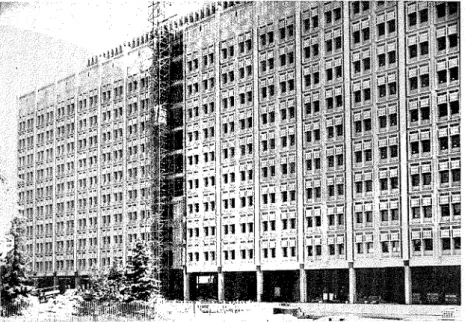
Fig. 2. View of south face of building at the time vibration measurements were taken
11. The main tower is connected to two adjacent wings, which run north- south, on its east and west sides. These wings extend from the sub-basement to the second floor level. The connexions between the tower and the two wings consist of a 7 ft 4 in. projection of the tower floors at the west end of the building, and a projection of 21 ft 2 in. at the east end. At the junction of each of these projections with the adjoining wing there is a 19 in. wide expan- sion joint, made up of asphalt-impregnated fibreboard. In the calculations that follow, it is assumed that the expansion joints are sufficient to isolate the tower structurally from the two wings.
12. Along the south side of the building the ground surface is at first floor level and a 14 in. thick reinforced concrete wall extends two floors down to the sub-basement. On the north side the ground surface is at basement floor level, and there is only a one-storey basement wall. There are no basement walls along the east and west faces of the tower, because there is direct access to the adjacent wings.
13. Soil studies made by the Department of Public Works indicated that the overburden consists of 0-22 ft of stiff to highly plastic clay overlying 14-40 ft of firm glacial till. The bedrock is limestone with interbedded thin shale layers. The foundations of the columns and shear walls of the tower are carried by groups of Franki piles with 6-10 piles in each group. Each pile has a working load capacity of 100 tons and is at least 8 ft long. Where the sub-basement slab rests directly on the soil, the specifications required that the soil should be capable of sustaining 1000 lb/sq. ft.
C H A R A C T E R I S T I C S O F A M U L T I - S T O R E Y C O N C R E T E B U I L D I N G 14. The structural skeleton consists of a combined system of a frame and shear walls, both constructed in reinforced concrete. The exterior frames are made up of columns and spandrel beams, but the interior frames consist of flat slab construction (the slab is generally 81 in. thick with drop panels 7 ft 6 in. by 8 ft 6 in. by 14 in. around the columns). As shown in Fig. I@), the shear walls, occupying the central core of the tower, run from the sub- basement to the floor of the upper penthouse. Two extra shear walls are located in the central bay along lines 2 and 13, but these occupy only the area from the sub-basement to the first floor.
15. The shear walls provide a symmetrical distribution of stiffness in the structure; there are minor deviations from symmetry in the frames, but in the theoretical analysis it has been assumed that there is perfect symmetry of stiffness about the two geometrical axes of symmetry. Based on the cross- sectional area of the concrete sections, the ratio of second moment of area of shear wall to that of an individual column is of the order of 1500/1 about the long axis of the building, and 5011 about the short axis. The stiffnesses of the spandrel beams and exterior columns are approximately equal.
16. On the few occasions when a detailed correlation has been obtained between the measured and predicted stiffness of a multi-storey building,13 it has been found that the building is much stiffer than was predicted. Internal partition and load-bearing walls can provide considerable stiffness in a build- ing and, in order to eliminate these factors from the analysis, the measurements were taken before any work had been started on this type of construction. The exterior curtain wall had been completed, however, except for one bay on the south wall (Fig. 2).
Vibration measurements
17. The methods of measuring the modes and frequencies of vibration have been described in some detail in previous papers,11*12 but for the sake of completeness the basic details are briefly described in the following paragraphs. 18. Six Willnlore Mark I1 seismometers were used to record the wind- induced vibrations of the building. These are sensitive electromagnetic transducers with a fixed coil and a heavy magnet that acts as the moving mass. The natural periods of the transducers were set at 2 s, and electrical damping was provided equivalent to 0.65 of the critical value. Thus, the transducer response could be expected to be flat over the frequency range of the building's vibrations. The electrical outputs from the seismometers were fed into a mobile laboratory where the signals were passed through d.c. amplifiers, and the amplified signals were recorded on a seven-channel f.m. tape recorder.
19. The measurements were taken in the following manner. The trans- ducers were placed on floors 2, 3, 4, 5, 6 and 7, in the centre of the building to reduce the signal that might arise from torsional vibrations of the building. Records were taken for
2
h for the lateral vibrations about one of the main axes of the building; the transducers were then rotated through 90" and records taken for another2
h for vibrations about the other main axis. The trans- ducer on floor 7 was then left in place, and the other transducers moved up to floors 8, 9, 10, 11 and the roof of the tower. Records were again taken as for the lower floors.W A R D
20. The frequencies and modes of vibration of the building were obtained from an analysis of the data stored on the magnetic tape. The tape was made into continuous loops and a Honeywell-Brown analyser was used to make a Fourier analysis of the records. Peaks in the Fourier analysis indicated the natural frequencies and the amplitude of the vibration. In order t o draw the mode shapes, the phase relations between the vibrations of the different floors were determined by comparing the results of first adding and then sub- tracting the vibrations recorded on two different floors.
21. By repeating this process for all the records obtained on the different floors it was possible to determine the first three lateral modes of vibration of the building about each of the main axes. The results of this process are shown in Figs 3 (a) and (b), where the mode shapes are drawn with respect to arbitrary scales. The absolute value of the displacements will obviously depend on the applied force, but the relative relation between amplitudes in any of the modes will remain the same as that shown in Figs 3 (a) and (b). Although it was not possible to define the fourth mode shape, some of the records con- tained frequency peaks that could have represented this mode. The measured values of frequencies for the first four modes are given in Tables 1 and 2.
22. The maximum displacements that were measured during this work were the displacements of the tower roof in the fundamental mode for lateral motion about the two axes. These displacements were of the order of 0.005 in. for a wind velocity of approximately 15 mile/h. For motion perpendicular t o the long axis the ratios of the maximum measured amplitudes in the first, second
and third mode were respectively 1 :0.4:0.1. The corresponding ratios for the
other axis were 1:0.5:0.25. I t can be seen therefore that the wind pre- dominantly excited the fundamental modes of the building.
Calculation of modes and frequencies of vibration
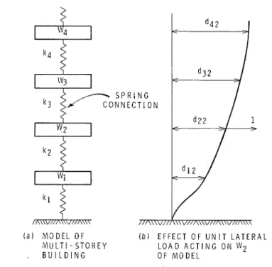
23. I n a multi-storey building most of the weight of the structure is con- centrated at each floor level, and the free vibrations of the structure can be obtained by considering the behaviour of a concentrated mass system. Hence, for lateral, torsional or vertical modes of vibrations there are as many degrees of freedom as there are floors. Fig. 4 shows a diagrammatic representation of a concentrated mass system and the parameters required to determine the free vibrations of such a system. When the lateral vibrations of a tall build- ing are being considered the spring connexions of interest provide resistance to horizontal motion.
24. The equations of motion of any structure can be expressed in terms of its flexibility or stiffness matrix. A computer program based on the Stodola method,14 was used t o calculate the modes and frequencies of vibration. With this method the lowest modes of vibration are obtained initially if the flexibility matrix is used, whereas the highest modes are obtained with the stiffness matrix. As it was the lowest modes of vibration that were recorded (and in general these modes are the most important) it was necessary t o calculate the flexibility matrices of the theoretical models.
25. The structural analysis involved the determination of the deflexions at all floor levels when a unit horizontal force was acting on one of them; in this way it was possible to determine one column of the flexibility matrix. The process is demonstrated in Fig. 4(b). I n some cases it was easier to calculate
C H A R A C T E R I S T I C S O F A M U L T I - S T O R E Y C O N C R E T E B U I L D I N G P E N T H O U S E
1
:::lR
- R O O F \\ '
.\
B A S E M E N T S U B - B A S E M E N T 3 2 1 0 1 2 4 3 i 1 0 1 2 3 4 ( a ) A L O N G S H O R T A X 1 S ( b ) A L O N G L O N G A X I S Fig. 3. Measured modal deflexionsthe stiffness matrix, and the flexibility matrix was obtained by matrix inversion. From the limited amount of information a ~ a i l a b l e l ~ . ~ ~ it appears that damping in modern buildings is small, and this was assumed to be the case in the subse- quent theoretical analyses.
Theoretical models and methods o f analysis
26. The lateral stiffness of the building under consideration is provided by two distinct structural systems: the shear walls and the framed part of the building. In the different models that were investigated it was assumed that these two systems either acted independently, or were interconnected in such
( a ) M O D E L O F ( b ) E F F E C T O F U N I T L A T E R A L M U L T I - S T O R E Y L O A D A C T I N G O N
w2
. B U I L D I N G O F M O D E L
Fig. 4. Concentrated mass representation of a multi-storey building
a manner that for any given floor level the displacements of the two systems were equal. In effect this latter condition assumes that the in-plane stiffness of the floor system is high.
27. In the majority of the calculations it was assumed that the structure was founded on a rigid base so that there was no lateral motion at the sub- basement level. The effect on one of the models when this restraint is removed was also investigated, and will be described later. In most cases it was assumed that the weights of all the floors up to the roof of the tower were equal, and the weights of the penthouse floors were 18.7% of this weight (the weight was taken to be proportional to the floor plan area). In the structural analysis the stiffness of any concrete member was based simply on its cross- sectional area.
Shear w a l l models
28. Since the shear walls are apparently much stiffer than the columns of the frame for lateral motion along the short axis, the first model that sug- gested itself was a consideration of the shear walls acting on their own. In this case it was assumed that the shear walls could be represented by a number of free-standing cantilevers connected by rigid diaphragms at each floor level. Because the second moments of area of the individual cantilevers were similar, it was possible to add together the individual moments of area between each
C H A R A C T E R I S T I C S OF A M U L T I - S T O R E Y C O N C R E T E B U I L D I N G floor a n d analyse a n equivalent single cantilever, which had a varying second moment of area along its height. The flexibility matrix of the cantilever was obtained by means of the moment-area method.
29. F o r vibrations along the long axis a model consisting of shear walls acting as cantilevers did not seem reasonable a n d therefore was not considered.
Shear frame models
30. Results from previous work7-l1 have shown that, for framed structures u p t o 20 storeys, good agreement can be obtained between theoretical a n d measured values of vibration characteristics when a shear frame model is assumed. In this model the flexural rigidity of the beams o r slab system is assumed t o be much greater than tliat of the columns, s o that there can be n o rotation of the joints in the frame. T h e agreement of computed results appears t o be good, even when the stiffnesses are of the same order of magnitude. T h e structural analysis is very simple in this instance because the model can be represented by a series of masses with spring connexions only between adjacent floors (Fig. 4(a)). I t must be remembered, however, that the springs provide resistance to lateral motion rather than the vertical motion implied in Fig. 4(a). 31. The masses in the model are equal t o the masses of each floor, a n d the spring value, lc, between any two adjacent floors is given by
1 2 E
lc = XIC0l
. .
.
.
. .
.
(1)where E is Young's modulus
L is the distance between the two floors, a n d
XIcoI is the summation of the values of the second moment of area of
the columns between the two floors.
32. Although this method of analysis provides the elements of the stiffness matrix, there is n o need in this case t o resort t o the process of matrix inversion in order t o calculate the flexibility matrix. When the values of k t for the build- ing have been obtained from equation (I), it is possible to calculate directly the flexibility matrix. This is achieved by considering the representation in Fig. 4(a), a n d using the fact that vertical loads a n d displacements represent the lateral loads a n d displacements. Thus suppose the displacements d12, C I ~ ~ , c132 a n d in Fig. 4(b) are required. A unit force acting upwards o n Wz would displace Wl, Wz, W3 a n d W4, respectively, by the amounts l/lcl
,
(l/lcl+
l/lc2),
( l / k l+
l/lc2) a n d (Illel+
l//cz), a n d these represent a column of the flexibility matrix. If this process is repeated for all the floors it is possible t o calculate the full flexibility matrix of the system.33. The independent shear frame models investigated in this study were obtained by ignoring all parts of the shear walls, except those portions on the frame centrelines with the same cross-sectional areas as the colunlns in the framed part of the building. Both fixed and pinned conditions were con- sidered for the degree of fixation of the c o l u ~ ~ i n s at sub-basement level.
Combined models
34. The most realistic model t o represent the structure consists of a system tliat incorporates the combined action of both the shear walls a n d the framing. I n the analysis of this type of model it was assumed that the frames a n d shear
W A R D
walls were linked at each floor by a rigid diaphragm, so that all components were subjected to the same displacement at any floor level. It was also assumed that only horizontal reactions between the frame and the shear wall system were mobilized. In other words, the effects of vertical shear forces and bending moments in the beams connecting the frames to the shear walls were ignored. The effects of shear deformations and rotary inertia were also omitted.
35. The combined models considered here can be represented by a number of parallel systems each consisting of interconnected masses and springs. Within the assumptions described, it is possible to calculate the stiffness matrix of the combined system merely by adding together the stiffness matrices of the separate systems. The method of analysis thus consisted of evaluating the combined stiffness matrix, then inverting this matrix to obtain the flexibility matrix of the combined system.
36. The first type of combined model to be considered was the combination of shear walls and shear frames. This particular model was investigated for lateral motion about the two main axes of the building. Finally, for lateral motion perpendicular to the long axis, an attempt was made to formulate a more realistic model by assuming that the shear walls were combined with frames in which joint rotation occurred. In this final model it was assumed that the second moment of area of each horizontal member in the frame was 50000 in.4; this was of the same order as the values for the majority of columns in the building.
37. T o derive the combined stiffness matrix of this final model it was necessary to calculate the stiffness matrices of the multi-storey frames along the lines 1, 2, 3, 4 and 7 in Fig. l(b). Because of symmetry, only half the structure had to be analysed. The analysis for the different frames was per- formed by the moment distribution method. In all the combined models it was assumed that the frames had fixed-ended supports at the sub-basement level.
Results for rigid base models
38. In the structural analysis of the building, all flexibility coefficients were expressed in terms of the constant (H3/EZ) so that it was possible to calculate the natural frequencies of vibration, f, of the building from an equation of the form
Here 12 is a computer-derived number related to the flexibility coefficients W is the weight of a typical floor in the tower section
H is the height of the building E is Young's modulus of concrete g is the acceleration due to gravity
and Z is a value for the second moment of area of a characteristic section in the theoretical model.
39. Values for I and H were known with a fair degree of accuracy, but it was more difficult to be precise about E and W. Consequently, two values for the frequencies of vibration of the models were calculated by using upper
CHARACTERISTICS OF A MULTI-STOREY CONCRETE B U I L D I N G and lower estimates of the ratio E/ W. The upper and lower values used for
E were 4 x loG and 2 x loG lb/sq. in. and for W were 2.8 x loG and 2.5 x loG lb. These yield 1.6 and 0,714/sq. in. for the two values of
El
W. The value of g was taken to be 32 ft/s2 and H was 178 ft. The natural frequencies of the various models calculated with these values are shown in Tables 1 and 2. Two values are given for each modal frequency. The first value refers to the case when E/ W = 1.6/sq. in. and the second value to the case when E/ W = 0.714/sq. in. The computed mode shapes are not affected by changes in the values ofEl
W.The last set of figures in Table 1 (Model 3c) was obtained by assuming the 1 lt h floor was 30% heavier than the other typical floors since it was designed for and carried the mechanical equipment in the building.
40. It is not practical to present all the calculated mode shapes, but in Fig. 5 a few of them are plotted for models that appear to give the best overall agreement with the measured frequencies. For motion along the short axis, the model chosen is the shear frame with pinned connexions at the foundation; for the other axis the model is the shear frame model with fixed-ended base- ment columns. The respective mode shapes are shown in Figs 5 (a) and (b). 41. The mode shapes are again plotted in terms of arbitrary scales, since the relative values of the amplitudes remain constant. A comparison of Figs 5 and 3 shows that the theoretical mode shapes are similar to the measured ones. Measurements were not made on the penthouse, so the amplitudes in this section of the building cannot be compared.
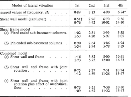
Table 1. Modal frequencies for motion along short axis
1. Shear wall model (cantilever)
. . . .
/
0.51t 2.96 6.70 9.56 0.76 4.42 10.02 14.30 Modes of lateral vibrationMeasured values of frequency, Hz
. . .
2. Shear frame model
(a) Fixed ended sub-basement columns.
1st 2nd 3rd 4th
0.89 3.13 4.90 6.94*
(b) Pin ended sub-basement columns
.
3. Combined model
(a) Shear wall and frame
. . . .
(b) Shear wall and frame with jointrotation
. .
. . .
. . .
(c) Shear wall and frame with joint rotation plus effect of mechanical floor
. . . .
..
*
There is some uncertainty in the jdentification of this mode.t
The two values for the frequencies are for El W= 1.6 and 0.714, respectively.W A R D
Table 2. Modal frequencies for motion along long axis
Modes of lateral vibration
I
1st 2nd 3rd 4thMeasured values of frequency, Hz.
.
..
I--
0.93 3.04 5.38 7.25*--
1. Shear frame model
(a) Fixed ended sub-basement columns.
Effect o f the restraint of the foundation
0.73t 2.18 3.46 4.36
1.09 3.26 5.19 6.52
(b) Pin ended sub-basement columns .
0.94 3.02 4.84 6.01
42. All the results described s o far involved the assumption that the building rests o n a rigid base. Previous experience of the Author with measurements o n other buildings has shown that it is difficult t o interpret the measurements of the vibrations of the foundation slab a n d so directly test the degree t o which this assumption is valid. Although these previous attempts were not investigated in any detail, one of t h e major difficulties was the presence in t h e records of comparatively high levels of vibration a t frequencies of the order of 15 Hz. These vibrations, which a r e probably caused by traffic movement, effectively mask the vibrations of interest.
43. T h e two simple forms of restraint that were investigated are shown in diagrammatic form in Figs 6 (a) and (b). Fig. 6(a) represents a system in which the weight of the foundation slab, W,, is assumed t o move laterally against a spring with a total stiffness k,. I n Fig. 6(b) lateral motion of the slab is prevented, but the foundation can rotate about a horizontal axis through the centre of the slab. In this latter case the factors that enter into the equations of motion are the polar moment of inertia of the slabs, J,, about this axis, and the rotational stiffness, kn, of the spring.
44. T h e model could be made more complicated by considering a com- bination of the two models, such that translation a n d rocking can occur simultaneously. But in view of the lack of any experimental evidence, it was considered that there was n o justification for making this refinement in the analysis a t this time.
2. Combined model
(a) Shear wall (without basement walls) and shear frame
. . .
.
.45. Both the foundation restraint models introduce a n extra degree of freedom compared with the rigid base models. In Fig. 6(a) the extra co- ordinate is
x,,
the lateral motion of the slab, and in Fig. 6(b) it is 8, therotation of the slab. The flexibility coefficients of both systems can be easily calculated from a knowledge of the flexibility matrix of the building founded o n a rigid base, and the values of kT or kR. I n this instance the rigid base model a n d the foundation restraint are two systems in series, in which case the
0.73 2.17 3.77 5.30
1.09 3.25 5.64 7.92
* There is some uncertaillty in the identification of this mode.
CHARACTERISTICS OF A MULTI-STOREY CONCRETE BUILDING
S U B
( a ) S H E A R F R A M E M O D E L ( b ) S H E A R F R A M E M O D E L A L O N G S H O R T A X I S A L O N G L O N G A X I S Fig. 5. Computed modal deflexions for rigid base model
flexibility matrix of the combined system is obtained by adding the flexibility matrices of the separate systems.
46. Thus suppose d 4 Z represents the deflexion of the fourth floor of the
rigid base model due to a unit load acting at the second floor. When the restraint in Fig. 6(a) is introduced, the new coefficient in the flexibility matrix becomes f4,, where
W A R D
( a ) T R A N S L A T I O N A L R E S T R A I N T ( b ) R O T A T I O N A L R E S T R A I N T
Fig. 6. Foundation restraints
Similarly the restraint of Fig. 6(b) leads to a new coefficient, r.42, where
In equation (4), hi is the distance from the foundation to the ith floor, and k E has units of torquelunit radian.
47. The equation for lateral motion of the foundation slab is in the same form as the equations of motion for the floors of the building. This is not the case for the rocking motion of the slab because the equations are expressed in terms of polar moments of inertia and rotations, rather than weights and deflexions. When the latter equation of motion is multiplied by the height of the building, H, however, it can be re-adjusted to have the same form as the equations for lateral motion.
48. As a consequence there was no need to make any significant alterations to the computer program in order to investigate the foundation restraints shown in Fig. 6. For the translational restraint the extra data required were the weight W , and the stiffness kT. These values were expressed in the following forms:
where n and b are the numbers read in as data by the computer, and the other symbols are as previously defined. For the rotational restraint the extra data were the polar moment of inertia, J,, and the stiffness, kR. These values were expressed in the form
J , = p H 2 W
C H A R A C T E R I S T I C S OF A MULTI-STOREY CONCRETE BUILDING
Table 3. Effect of foundation translation on modal frequencies. (Model 3b-shear wall and frame with joint rotation)
Foundation parameters
I
ModeI
2 3 4Same model on rigid base
. . .
. .
.
1
0.75 3.27 7.52 10.34 1.w,= w
kT = 1.29 x lo9 lb/in.
. .
.
. . .
= 8 . 6 ~ lo6 lb/in.
. . . .
= 8 . 6 ~ lo4 Ib/in.. . . .
. .
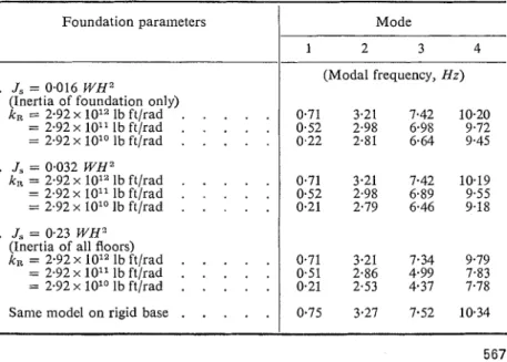
Table 4. Effect of foundation rotation on modal frequencies for motion perpendicular to long axis. (Model 3b-shear wall and frame with joint rotation)
I
(Modal frequency, Hz) 0.75 3.26 7.49 10.27 0.68 2.05 4 6 1 8.21 0.13 1.20 4.25 8.14
Foundation paraineters Mode
3 4
flnertia of all floors)
1
1. J, = 0.016 WH2
(Inertia of foundation only)
k , = 2.92 x 10¹² lb ftlrad
. . . . .
=2.92x1On1bft/rad.
.. . .
Same model on rigid base
.
.
.
.
.
1
0.75 3.27 7.52 10.34 (Modal frequency, Hz)0.71 3.21 7.42 10.20 0.52 2.98 6.98 9.72
W A R D
49. T h e frequencies arising from different values for the translational parameters a r e shown in Table 3. Corresponding values for the effect of the rotational restraint are given in Table 4. The values of kT and k , in Tables 3 a n d 4 were calculated by substituting the value E = 2 . 0 x l o G lblsq. in. in equations (5) a n d (6) respectively, a n d the values of the frequency a r e based o n the assumption that El W= 0.714/sq. in. The effect of other values of E a n d the ratio E / W o n the values of /cT, k R a n d the frequencies can be obtained from
equations (5), (6) a n d (2), respectively.
50. T h e range of values for lc. a n d lcn was selected as follows. The highest values of kT a n d lcR were chosen s o that the displacement of the basement floor due t o a unit load a t that floor was twice the value for the assumed condition of a rigid base. Similarly, the lowest values of kT and k , were chosen s o that the deflexion of the penthouse roof d u e t o a unit load a t that floor was also double the value for the rigid base model.
51. I t can be seen in Table 3 that a 100% increase in W, produces only a second-order effect o n the frequencies for the whole range of values of kT that were investigated. These results also show that as /cT decreases from co t o 8.6 x lo6 lb/in., there is a decrease in all the first four frequencies of vibration. As ItT is reduced further, however, the fundamental mode frequency decreases, but there is very little change in the higher mode frequencies.
52. The frequencies in Table 4 were calculated by using three different values for J,. The snlallest value for J, was obtained by assuming that the rotary inertias of all floors except the basement were zero, whereas the largest value for J, was calculated by including the rotary inertias of all floors.
53. The results when Js=0.0162 W H 2 a n d 0.0324 W H 3 show that only the fundamental mode frequency is appreciably influenced by the variation of
kn. When the rotary inertias of all floors are included, however, all four
frequencies are affected a s Ic, decreases from co t o 2.921 x 1Ol1 l b ft/rad, but any further reduction of /en has a major influence on only the fundamental mode frequency.
54. The results in Tables 3 a n d 4 show that with consideration of some foundation movement a reasonable fit with the measured results m a y be obtained. F o r E/ W = 0.714/sq. in. the translational restraint parameters W,= W, k,= 8.6 x 10"b/in. provide reasonable agreement with the measured frequencies of the first, third, a n d fourth modes, but give a poor estimate for the second mode. T h e rotational restraint o n the other hand provides a reasonable estimate for the second, third a n d fourth modes, when J, = 0.23 W H 2 a n d k R = 2.92 x 10¹¹ lb ft/rad, but underestimates the fundamental mode frequency.
55. T h e value of the foundation restraint obviously exerts a significant influence on the mode shapes. Thus as k , changes from co t o 8.6 x l o 4 lb/in., the fundamental mode changes from one where there is considerable relative displacement between floors t o o n e where there is little relative displacement. F o r the values of lcT=8.61 x l o 6 lb/in. a n d k,=2.92 x 1Ol1 l b ft/rad, however, the mode shapes are similar t o those shown in Fig. 5. Some of the details of the mode shapes when foundation movement is assumed are s l ~ o w n in Fig. 7.
Discussion of t h e results
56. Without any analysis, it may be observed that the ratios of the mea- sured frequencies suggest that the building behaves as a shear frame structure.
C H A R A C T E R I S T I C S O F A M U L T I - S T O R E Y C O N C R E T E B U I L D I N G - A 0 I I
.
A - 6 o FIRST MODE--
.
-2 1 0 1 2 3 2 1 0 1 2 3( a ) BASE TRAIdSLATION ( b ) BASE ROTATION
W, = 2 W k R
= 2. 9 2 x 1 0 1 1 Ib f t l r a d
Fig. 7. Some computed mode shapes for foundation-restraint models along short axis
W A R D
The modal frequencies are very close to the proportion 1 : 3 : 5: 7, which is characteristic of a simple shear frame system, rather than t o the higher propor- tion of 1:6: 17:34 that would be expected of a uniform cantilever structure. This trend is confirmed by a detailed examination of the various theoretical models considered in the calculations. The shear frame model in the direction perpendicular to the long axis appears to give the best agreement with measure- ments as shown in Table 1. This model cannot, however, be considered a realistic reflexion of the structural behaviour since the substantial stiffness of the shear walls is neglected.
57. The combined shear wall and frame model with the additional assump- tion of joint rotation gives good agreement for the frequencies of the first mode, but the values for the higher modes are too large. This would be expected, since in the assumed theoretical models the contribution of the shear walls in the cantilever bending mode is significant. If shear deformations in the shear walls were considered there would be very little change in the fundamental frequency, but the second and third mode frequencies might be reduced by about 5% and 10% respectively.
58. I t is well to remember at this stage, however, that the results from wind- induced vibrations must be interpreted with some caution. The major dis- advantage of the method is that the resultant displacements are small, and there is a possibility that at these low levels of vibration some non-structural elements not included in the analysis can provide a contribution to the stiffness that might disappear at vibration levels which are of engineering significance. Although some recently published work16 on the forced vibrations of a two- storey building showed that the non-linear behaviour of the structure caused only a 3% shift in the resonance frequency, there is need for more research into this aspect of the dynamic behaviour of buildings to determine whether this order of magnitude is general for most types of structures.
59. The models investigated in this study were comparatively simple, and were mainly concerned with those factors that would have a first-order effect on the vibrations of a structure. Two of the more important second-order factors that were not considered probably tend to cancel each other out; these are the effects of axial deformation and the curtain walls. It can be expected that in buildings up to about 20 storeys the neglect of axial deforma- tions will lead t o an overestimation of the fundamental frequency by about 10%; for higher modes this error will decrease.17 On the other hand, the curtain walls will tend to increase the natural frequencies, and the work reported in Reference 16 indicates that this increase might be of the order of 10%.
60. An investigation of some foundation restraints represented merely by springs showed that this form of restraint can exert an appreciable influence on the first mode of vibration, but this influence decreases for higher modes. A comparison of the results in Tables 1 to 4 shows that the consideration of foundation compliance did not improve the agreement between measured frequencies and those computed from the assumed models. On the contrary, the ratios of frequencies of ascending modes of the various models become larger than the frequency ratios of the corresponding models without founda- tion movement, and consequently are even further removed from the ratios of the measured frequencies.
C H A R A C T E R I S T I C S OF A M U L T I - S T O R E Y CONCRETE B U I L D I N G information available on the topic. There is a need for more knowledge about the reactions of actual foundation systems to dynamic loads.
Conclusions
62. In order to improve the methods of earthquake-resistant design of multi-storey structures it is necessary to establish procedures by means of which calculation of reasonable estimates for the modes and frequencies of vibration of these buildings is feasible. The simple models discussed in this Paper indicate to some extent that it is possible to achieve this aim. The results for the structure under consideration have shown that the frequencies of an idealized shear frame model give good agreement with the measured frequencies in the long direction of the building. In the short direction the agreement between measured and computed results is less satisfactory. Further research into the dynamic behaviour of frame structures with shear walls is indicated.
63. Perhaps the most important type of information that is required consists of comparisons between the measured and predicted dynamic charac- teristics of numerous buildings. The analysis of wind-induced vibrations can readily provide the measured characteristics, but the possible non-linear behaviour of structures at low amplitudes of vibration may be a source of error, particularly in the higher modes of vibration.
Acknowledgements
64. The Division of Building Research, National Research Council, wishes to thank the Department of Public Works, and in particular Mr W. A. Ward, Head of the Building Structural Engineering Division, for permission to use the building as described. The Author is grateful to Mr Ward, to Massey and Flanders, architects, and to Carruthers and Wallace, structural consul- tants, for their co-operation in developing the structural analysis. This Paper is a contribution from the Division of Building Research, National Research Council of Canada and is published with the approval of the Director of the Division.
References
1. CLOUGH R. W. Earthquake analysis by response spectrum superposition.
Bull. seisrrz. Soc. Am., 1962, 52 (3) 647-660.
2. JENNINGS R. L. and NEWMARK N. M. Elastic response of multi-storey shear beam type structures subjected to strong ground motion. Proc. 2nd World Cori-
fererzce on Earthqzlake E~zgineerinzg, 1960, Vol. 2, 699.
3. ROSENBLUETH E. Earthquake resistant design. Appl. Meclz. Rev., 1961,14 (12), 923-926.
4. U~zifornz Bz~ildi~zg Corle, 1961 Edition, Vol. 1, Section 2313.
5. Eartlzquake investigationzs in Calijornzia 1934-1935, US Coast and Geod. Survey, Special Publication No. 201, US Dept of Commerce, Washington, DC, 1936. 6. TAKENCHI M. and NAKAGAWA K. Vibrational characteristics of buildings.
Proc. 2nd World Conference on Earthqzzake Etzgitzeerinzg, 1960, Vol. 2, 961-982. 7. HOUSNER G . W. and BRADY A. G . Natural periods of vibration of buildings.
J . Engnzg Mech. Div. Proc. Am. Soc. civ. Enzgrs, 1963, 89 EM4, 31-65.
8. KANAI K. and YOSHIZAWA S. On the period and damping of vibration in actual buildings. Bull. Eartlzq. Res. Znst., Tokyo Univ., 1961, 39 (3), 549-559.
W A R D
9. GOLDBERG J. E. et al. Forced vibration and natural frequencies of tall building frames. Bull. seisrrz. Soc. AIII., 1959, 49, 33.
10. RUBINSTEIN M. F. and HURTY W. G. Effect of joint rotation on dynamics of structures. J. Erzg. Meclr. Div. Proc. Arn. Soc. civ. Erlgrs, 1961, 87, 135-157. 11. CRAWFORD R. and WARD H. S. Determination of the natural periods of build-
ings. BIIII. seism. Soc. AITI., 1964, 54, 1743-1756.
12. WARD H. S. and CRAWFORD R. Wind-induced vibrations and building modes.
Bull. s e i s ~ r ~ . Soc. Am., 1966, 56, 793-813.
13. WOOD R. H. and MAINSTONE R. J. Stress measurement in the steel frame of the new government building-Whitehall Gardens. Confererzce on the Correlation
betrveen Calcz~lated ar~rl Observecl Stresses and Displacerr~er~ts in Strnctures.
Institution of Civil Engineers, 1955.
14. BIGGS J. M. Introduction to structural dynamics. McGraw-Hill, 1964, 97-111.
15. NIELSON N. N. Dynamic response of multi-storey buildings. PhD Thesis, California Institute of Technology, May 1964.
16. BOUWRAMP J. G. and BLOHM J. K. Dynamic response of a two-storey steel frame structure. Bull. seisrr~. Soc. Arn., 1966, 56 (6), 1289-1303.
17. CLOUGH R. W. et a/. Structural analysis of multi-storey buildings. J. Struct.
Repritited from Ptoc. Itlsttr ciu. Et~gts, April, 1970
71
73
DISCUSSION
Dynamic characteristics o f a multi-storey
concrete building
H. S. WARD D. A. H o w e l l s and Dr B. N a t h
ard's Paper contains a valuable discussion of the way in which foundation lity may affect the frequencieq and mode shapes of lateral vibration of a multi- building. It would be Interesting to carry this further, and to consider values ndation flexibility which may be met in reality and how these may be determined accurately than hitherto possible by using numerical methods, assuming of
that elastic conqtants o f the soil are known sufficiently accurately.
In the co~nmonly accepted simplification o f considering the structure as a two 'onal problem in rclation to each o f two axes and suppressing the motion along d dimension, there are two degrees of foundation freedom for each plan axis, translation and rocking. These cause two very different stress patterns in the soil and in extreme cascs of, for example, stratification it [nay be desirable to use different elastic constants of the soil for each type of motion. In many cases, how- ever, other sources o f inaccuracy may mask lack of accuracy in the choice of elastic constants, so that ovcrall values can be used for both types of motion. I n most cases it would be reasonable to assume a value of Poisson's ratio based o n an inspection of the cotes taken during the site investigation. A wave velocity determination will then enable the Young's n~odulus to be calculated, though at the high values of Poisson's ~ a t i o ~lsually encountered in soil dynamics it may eventually be found more convenient to express formulae in terms of one of the other elastic constants.
67. The cvaluation o f the spring constants and 'equivalent mass' of soil for a material of known elastic constants is the next step. Analytical solutions to the equations of motion have been found for certain boundary conditions, but more rcalistic exaluplcs call for numcrical methods of analysis to account for the embedment of basement storeys and, where required, plan shape of the building. For motion along the short axis of a long buildlng a two dimensional analysis using finitc differences leads to a solution for the dynamic behaviour of the soil.18 Br~efly, in the case of a n cmbcdded rigid foundation block, for cxample, Lamb's cqi~ations of motion can be approximated by their finite dirierence counterpa~ts, in which the two components of linear d~splacemcnt arc thc unknowns to be dctermlned. When relevant boundary conditions arc introduced in these equations, ~ncluding for example that during ver- tical translation, all points on the block have the salne dlsplacement at a given time and the whole problem reduces to finding thesc displacement components at the pivotal points, for a given frequency of motion. The problenl is now casily solved for steady- state conditions of motion, since the original equations reduce to a set of simultaneous equations with co~nponents of displacement as unknowns. Once these components at the pivots havc becn determined, contact pressures under the foundation at a given frcquency and subsequently the spring constant can be determined. The computer program can as readily tackle the case of rocking motion.
68. The spring constants, both for translation and rocking, are found to be f ~ ~ n c t i o n s of the exciting frequencies and the method of finite differences outlined above makes it possible to determine this relationship. A more realist~c and logical assessment of problenis such as that in D r Ward's Paper would result from the cvaluation of frequency depcndcnt spring constants obtained by means of numcrical
procedures.
69. For ~liultistorey structures foundat~on flexibility should not be allowed to have
PA-
Papcr publ~shcd: Ptoc. lrr~ttr t i c . h g r s , 1969, 43 (Aug.) 553-72.
D I S C U S S I O N
a significant effect on the dynamic properties of the structure. If foundation flexibility lowers the fundamental frequency by more than 10% from that calculated for a rigid base it would be wise to reconsider the whole project. This sort of analysis will give valuable guidance to the structural designer even when the elastic constants of the foundation material are not known with great precision.
Dr H. S. Ward
The Author is essentially in agreement with everything Mr Howells and Dr Nath say. As a consequence of trying over a period of five years to correlate experimentally determined dynamic characteristics of tall buildings with theoretical predictions, it became apparent that the factor about which there was least information was the effect of foundation flexibility or more precisely foundation impedance. Neverthe- less the simple models used in the Paper t o represent foundation impedance were not intended to represent the most realistic situation possible, but merely to see if the inclusion of the extra degree of freedom might account for the relatively poor agree- ment between the ratios of the measured frequencies and the theoretical values obtained when a rigid base was assumed.
71. It is important of course t o develop theoretical techniques that account for ground structure interaction, such a s that outlined by Mr Howells and D r Nath. If these theoretical methods are t o reflect truly the performance of actual foundation systems, however, they must incorporate information obtained from experimental ob- servations of such systems. This input of experimental evidence is essential since with our present knowledge of soil mechanics it is unrealistic t o predict the dynamic properties of soils from theoretical considerations.
72. Although experimental work in this area dates back to the DegebolS study in 1933, there is still a need for careful experimental work because there are many pit- falls for the unwary. With this view in mind the Division of Building Research of N R C are embarking on an experimental programme which will investigate the dynamic impedances of small sized foundation elements (plan dimensions of the order of 10 ft). These measurements will be correlated with such factors as soil profiles and soil strength properties obtained from core samples. The information will also be used to see if it is possible to extrapolate to the dynamic behaviour of actual build- ing foundation systems.
73. It is difficult to be explicit about how much one should allow the foundation flexibility to lower the fundamental frequency of multistorey structures. It might be argued that a 10% reduction from that calculated for a rigid base could be an indication of poor soil strength. On the other hand there are instances in North America where economic factors have encouraged the use of raft foundations rather than piles as the means of supporting multistorey structures on sensitive leda clays. It is conceivable that this solution might lead t o more than a 10% reduction in funda- mental frequency. In view of our limited knowledge in the area of the dynamic behaviour of foundation systems, however, the figure of a 10% reduction might serve a s a limit beyond which more caution should be exercised.
References
18. NATH B. Effect of embedment on static and dynamic contact pressures under a strip footing. (To be published.)
19. HERTWIG A. ei 01. Die Ermittlung der fur das Bauwesen wichtigsten Eigen- schaften des Bodens durch erzwungene Schwingungen. Spritlger, Berlin, 1933.
The Institution as a body is not responsible for the statements made or for the opinions expressed i n the foregoing pages.