HAL Id: hal-00942200
https://hal.archives-ouvertes.fr/hal-00942200
Submitted on 12 Feb 2014
HAL is a multi-disciplinary open access
archive for the deposit and dissemination of
sci-entific research documents, whether they are
pub-lished or not. The documents may come from
teaching and research institutions in France or
abroad, or from public or private research centers.
L’archive ouverte pluridisciplinaire HAL, est
destinée au dépôt et à la diffusion de documents
scientifiques de niveau recherche, publiés ou non,
émanant des établissements d’enseignement et de
recherche français ou étrangers, des laboratoires
publics ou privés.
DESIGN PROCESS OF THE INTERLOCK SYSTEM
FOR THE COMPACT LINEAR COLLIDER
Patrice Nouvel, Bruno Puccio, Jonker Michael, Hélène Tap
To cite this version:
Patrice Nouvel, Bruno Puccio, Jonker Michael, Hélène Tap. DESIGN PROCESS OF THE
INTER-LOCK SYSTEM FOR THE COMPACT LINEAR COLLIDER. International Particle Accelerator
Conference, May 2013, Shanghai, China. �hal-00942200�
DESIGN PROCESS OF THE INTERLOCK SYSTEM FOR THE COMPACT
LINEAR COLLIDER
P. Nouvel
1,2,3, B. Puccio
1, M. Jonker
1, H. Tap
2,3,
1CERN, Geneva, Switzerland
2
CNRS, LAAS, 7 avenue du colonel Roche, F-31400 Toulouse, France
3Univ de Toulouse, INP, F-31400 Toulouse, France
Abstract
The Interlock system forms a critical part for the ma-chine protection of linear colliders. Its goal is to inhibit the next pulse either on failure of critical equipment and/or on bad beam quality evaluation. This paper presents the on-going process to validate design choices for the Compact Linear Collider (CLIC) Interlock System. The design pro-cess starts by establishing requirements. In mission-critical system case, these requirements mainly focus on the de-pendability. Furthermore, the new concept of fast beam quality analysis has been introduced into the CLIC Inter-lock System and will be discussed in this paper. To support the design process, experimentation with this concept has been launched. In addition, a hardware demonstration of the Interlock System was set up to validate that the design is in concordance with the requirements.
INTRODUCTION
In high energy accelerators field, Interlock Systems are key part of the machine protection systems. At CERN, an Interlock System has been designed for the Large Hadron Collider (LHC). Its development process has brought the usage of a safety-system and systemic approach, resulting in a formalization of the lifecycle of a protection system [1]. The protection systems for the new generations of high power machines, such as the Compact Linear Col-lider (CLIC), will benefit from this experience and shall integrate this approach in the early stage of their design process.
After introducing the framework, this paper presents the steps of the design process for Interlock System applied to CLIC. The first part describes the requirements establish-ment. The second part presents the design phase. Finally, the last part gives details about the validation. This process has been inspired by the above mentioned protection sys-tem lifecycle and the IEEE 1220-2005 standard : Applica-tion and Management of the Systems Engineering Process.
CLIC INTERLOCK SYSTEM
FRAMEWORK
CLIC is a linear lepton (positron-electron) collider in the multi-teraelectronvolt (3 TeV) range, designed with a novel two beam approach. It aims to perform precision measure-ments of the new physics discovered by hadrons colliders (such as the LHC).
The CLIC has a large beam power (up to 70 MW) that can easily destruct part of the machine equipment. More-over, there are many types of failures that can lead to machine damage; fast failures (e.g., accelerating structure breakdown), inter-cycle failures (e.g., equipment break-down) and slow failures (e.g., alignment drift). Conse-quently, several protection strategies have been foreseen [2]: e.g., passive protection, preventing system.
The Interlock System is a key part of the machine pro-tection framework. Its purpose is to increase the machine safety while not decreasing significantly its availability. It is done through preventing uncontrolled energy losses. The interlock system prevents uncontrolled energy losses either by dumping the active beam in the machine or by inhibiting the next machine cycle.
In the CLIC case, at each inter-cycle (i.e., between two pulses), a permit is released. A VETOdecision inhibits the beam while a PASSdecision does not. This inhibition can be triggered by two types of stimuli. The first type comes from critical equipment of the machine. Equipment is con-sidered as critical when its failure mode may lead to dan-gerous beam instability. The second type of stimulus comes from the post-pulse analysis done by the Interlock System. This analysis aims to perform a fast beam quality analysis on each pulse during the inter-cycle in order to assert the beam stability.
REQUIREMENTS ESTABLISHMENT
The first step of the design process is to establish require-ments. In addition to the functional requirements, the Inter-lock System has two principal performance requirements.
Response Times
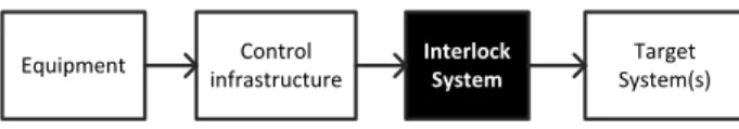
The response time between a failing equipment and the actual machine interlocking must be inferior to 2 ms [2]. The Interlock System is on the critical path (cf. Figure 1) and must be able to change the permit in a fraction of this time. Equipment Control infrastructure Interlock System Target System(s)
Secondly, the post-pulse analysis must be done between two pulses. Considering a 100 Hz beam operation and a delay of 2 ms to receive data, it leaves a maximum time of 6 ms, as shown on Figure 2. Pulse Next Pulse 2 ms Data reception Permitdelivering Inter-cycle: 10ms 2 ms 6 ms Post-pulse analysis processing
Figure 2: Response times requirement
Dependability
A central attribute of the Interlock System is the depend-ability and more precisely, its relidepend-ability and availdepend-ability.
The determination of these requirements has been done with the methodology from the protection system life-cycle. The first task has been to identify the risks. The hazard chain (Figure 3) helps to analyse which chain of events the interlock system shall prevent.
Critical Equipment Failure(s) Beam Instability Uncontrolled Energy Losses Machine Damage Slow failures Fast failures Equipment based Interlock Post-Pulse Analysis
Figure 3: Hazard Chain
In the following step the covered risks are analysed. As a first estimate, the figures are based on operational statis-tics of LHC (Table 1). The consistency of these rates was cross-checked with a method based on availability assump-tions. For a next iteration these rates should be issued from a complete CLIC failures catalogue.
Table 1: Risks analysis synthesis Type of failure Machine Failure Rate Critical Equipment 2.65 ∗ 10−7pulse−1
Slow Beam instability 3.33 ∗ 10−8pulse−1
After setting the reduction risk to be achieved, the third step is to define the tolerable failure rate for the Interlock System (Table 2).
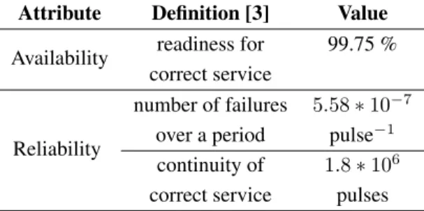
These failure rates have been translated into require-ments on reliability and availability, as shown in Table 3.
DESIGN
The design step is conditioned by the interfaces of the interlock system, the functions to implement and the archi-tecture of CLIC.
Table 2: Protection Function specifications Interlock System Failure Mode Failure Rate False PASSdecision 4.17 ∗ 10−6pulse−1
Transient false VETOdecision 0.1h−1
Permanent false VETOdecision 2year−1
Table 3: Interlock System Dependability Attribute Attribute Definition [3] Value Availability readiness for 99.75 %
correct service
Reliability
number of failures 5.58 ∗ 10−7
over a period pulse−1
continuity of 1.8 ∗ 106
correct service pulses
Interfaces
As shown in Figure 1, the Interlock System is interfaced mainly with two other systems.
Both the data to assert the beam quality and the data re-lated to equipment failures are obtained through the same acquisition and control infrastructure. This data is acquired in 20’000 crates along the main Linac, assembled and then dispatched to users tasks running in concentrator crates at the 48 tunnel access shafts. The beam permit (generated by the Interlock System) is delivered to the actuator(s), called target system(s). In the case of CLIC, the targets are amongst others, beam source inhibits, extraction kicker inhibits, dump kickers.
Functions
As for the LHC, the beam permit loop (cf. Figure 4) is the backbone of the Interlock System, transmitting the beam permit. A signal is generated by the voting node (i.e., the master) on every single loop. Every node (i.e., the slaves) has the ability to open the loop and will do so as soon as the beam operation is not safe. The permit loop is multiplied to reach the dependability attributes, requiring thus a voting system (e.g., 2-out-of-3).
1 2 i 94
Voting System
Figure 4: Beam Permit Loop
The detection of unsafe conditions (linked to equipment failures or beam losses) is done by threshold comparison.
This allows the usage of a standardized interface for all type of incoming data. The thresholds are defined and managed by their field experts.
In order to assure the post-pulse analysis in the expected time, this idea is to synthesize the data up to the master node. Moreover, an extra layer of concentrating module al-lows to implement local rules and it complements the local threshold comparison with a global analysis.
Layout
Combining the functions and the constraints of the inter-faces with the CLIC architecture, the overall system layout is synthesised in Figure 5.
Beam Permit Loop
Master Interlock
Concentrator - Global Analysis
Front-End
[...]
[...]
Figure 5: Interlock System architecture
VALIDATION
Feasibility study
Before advancing further in the design process, a feasi-bility study is required to validate the design choices.
The beam permit loop is used in the LHC [4] where its feasibility has been amply demonstrated.
Concerning the post-pulse analysis, some existing sys-tems are using related principles [5] [6] but do not integrate the full concept. Consequently, an experiment has been de-veloped (through a JAVA application) in the CTF3 (CLIC Test Facility 3). This demonstration is a beam sequencer applying the post-pulse analysis concept. As a result, it has identified the key points of the concept such as the thresh-old management, the type of incoming data and the needed strong coordination with the accelerator mode.
Hardware validation
To demonstrate that it will meet the proposed system de-sign, the last step of the process is to prove it will reach the established requirements.
For this purpose a prototype, scaling-down the Interlock System, has been developed with the aim to measure the performance of the system. Once these measurements are made, they must be extrapolated to the CLIC scale by con-sidering the number of modules and the inter-module dis-tance.
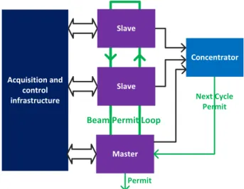
The synoptic of this prototype is shown in Figure 6. It is based on five boards, each one with an FPGA as its core. A FMC (FPGA Mezzanine Card) connector allows differ-ent front panel solutions. Each board represdiffer-ents a module
(master, slave or concentrator) and the last board is used to emulate the acquisition and control infrastructure. The data communication is done with gigabyte transceivers.
The main performances to measure are:
- The response time to trigger an interlock request. - The response time to perform the post-pulse analysis. - The failure modes characterization of a single node.
Acquisition and control infrastructure
Beam Permit Loop
Permit Master Slave Slave Concentrator Next Cycle Permit
Figure 6: Interlock System prototype synoptic
CONCLUSION AND PERSPECTIVES
To date, the response time to trigger an interlock request has been measured and extrapolated to 220 µs, giving a re-maining time of 1.58 ms for the acquisition infrastructure to transmit the data. The two other measurements are on-going.
Following this first process iteration, The new genera-tion should be integrated in the final adopted acquisigenera-tion and control infrastructure of CLIC. The system should be validated in an operational environment such as the CTF3 in pair with the test of the CLIC module prototype.
REFERENCES
[1] B. Todd et al, “Machine Protection of the Large Hadron Col-lider,” Proceeding of 6th International Conference on System Safety, 2011
[2] Michael Jonker and al., “The CLIC Machine Protection,” Proceeding of IPAC’10, 2010
[3] Algirdas Avizienis et al, “Fundamental Concepts of depend-ability,” 2001
[4] B.Todd et al, “The architecure, design and realisation of the LHC Beam Interlock System,” Proceeding of ICALEPCS, 2005.
[5] B.Todd, “The Safe Machine Paramters,” Technical report, EDMS 1096447, 2011.
[6] M. Zerlauth et al, “The Post-Mortem Analysis Framework,” Proceeding of ICALEPCS, 2009