Cold Side Thermal Energy Storage System For
Improved Operation of Air Cooled Power Plants
by
Daniel David Williams
Submitted to the Department of Mechanical Engineering
in partial fulfillment of the requirements for the degree of
Master of Science in Mechanical Engineering
at the
MASSACHUSETTS INSTITUTE OF TECHNOLOGY
INSTTE
ES
a se-E
September 2012
©
Massachusetts Institute of Technology 2012. All rights reserved.Author ...
Department of Mechanical Engineering August 20, 2012
Certified by... ... ... Alexander Mitsos Rockwell International Assistant Professor Thesis Supervisor
Accepted by ...
David E. Hardt Ralph E. and Eloise F. Cross Professor of Mechanical Engineering
Cold Side Thermal Energy Storage System For Improved
Operation of Air Cooled Power Plants
by
Daniel David Williams
Submitted to the Department of Mechanical Engineering on August 20, 2012, in partial fulfillment of the
requirements for the degree of
Master of Science in Mechanical Engineering
Abstract
Air cooled power plants experience significant performance fluctuations as plant cool-ing capacity reduces due to higher daytime temperature than nighttime temperature. The purpose of this thesis is to simulate the detailed operation of a cold side thermal energy storage system in order to evaluate its potential. An organic Rankine cycle geothermal power station is used as an example application. Detailed sizing and op-eration considop-erations are discussed. Several representative case studies compare the performance of candidate configurations. Operation of the selected configuration is then simulated for a full year and a proposed integration of the system with existing plant hardware is laid out. A correlation between weather trends and production is outlined. Finally an economic cost/benefit analysis performed to determine the payback period for implementing the proposed system.
The cold side TES system is shown to shift substantial power generation capability from nighttime to daytime when electrical demand is highest, especially during hot summer months. For example, daily energy production is shown to increase by up to 18% under particularly favorable conditions. This redistribution of the power generation curve is accomplished with less than a 5% reduction in overall annual energy production in Mega-Watt hours. The system is shown to be more effective at shifting power generation capacity during warmer months than cooler months. The reduced day to night temperature fluctuation during cooler months results in a reduced thermal storage benefit under similar parasitic loads.
The economic benefits of this system are dependent upon the on-peak vs off-peak electricity prices. Economic analysis using 2011 transient price data from the U.S. Midwest Region results in a small increase in annual income. The increased income from the proposed cold side TES system is found to be insufficient to outweigh the required capital investment at current electricity prices.
Thesis Supervisor: Alexander Mitsos
Acknowledgments
First and foremost, I am thankful to my advisor, Dr. Alexander Mitsos, whose guidance and support enabled me to develop this thesis from a concept to a completed work. His attention to detail and expertise were essential to ensuring a thorough study
and have greatly contributed to my own understanding of the subject matter. Equally important was Dr. Mitsos sincerity and encouraging demeanor in dealing with the challenges associated with splitting my time between my academic work and full time employment responsibilities.
I am grateful for the contributions of Dr. Hadi Ghasemi who was instrumental in solidifying my understanding of the operation of the Salt Wells geothermal facility. His modeling and data matching work regarding the existing plant machinery formed the foundation from which my proposed system model could be built.
I would like to acknowledge the technical contribution of Enrique Lizarraga who in the course of his thesis work developed a technique by which a modified 2D plug flow simulation may be used to model turbulent pipe flow heat exchange COMSOL Multiphysics@. This technique was responsible for a dramatic reduction in computing time versus employing a turbulent flow solver while still allowing precise control over the heat transfer characteristics of the system.
I would like to thank Nick Macini who developed the initial concept of a coldside thermal energy storage system. His preliminary hand calculations were the motivation for further study that eventually yielded this thesis.
I would like to thank Gina Zak for her constant patient assistance in teaching me several of the software applications required to prepare this work. I am particularly thankful for Gina's help while formatting and compiling this document.
I would also like to thank the General Electric Company for funding my graduate work and for facilitating a leave of absence to complete my thesis. The company's commitment to education is apparent in all levels of corporate leadership. I would like to thank Ken Gould, coordinator of the GE Lynn Advanced Course in Engineering, in particular for his steadfast encouragement and mentorship.
Contents
1 Introduction 19
1.1 Power Plant Heat Rejection Methods . . . . 19
1.2 Geothermal Power . . . . 20
1.3 M otivation . . . . 21
1.4 O bjectives . . . . 25
1.5 Model of Existing Plant . . . . 25
1.6 Proposed System . . . . 29
2 Procedure 31 2.1 T E S Sizing . . . . 31
2.2 TES Simulation with COMSOL@ Multiphysics . . . . 39
2.2.1 Metallic Pipes in TES Storage Block . . . . 40
2.2.2 Mesh Density Studies . . . . 41
2.3 Matlab@ with COMSOL Livelink@ . . . . 42
2.3.1 Ambient Temperature Data . . . . 43
2.3.2 Operating Mode Logic . . . . 43
2.4 Non-TES Heat Exchange Components Simulation and Design . . . . 45
2.4.1 Pseudo Steady-State Assumption for Condensers and Heat Ex-changers . . . . 45
2.4.2 Air Cooled Condenser Simulation . . . . 46
2.4.3 ACC Fan Count . . . . 49
2.4.4 Air Cooled Heat Exchanger Simulation . . . . 52
2.4.6 Oil Cooled Condenser Simulation 2.5 Oil Cooled Condenser Sizing Studies . .
2.5.1 Isobutane Model . . . . 2.5.2 Air M odel . . . . 2.5.3 Heat Exchanger Oil Model . . . . 2.5.4 Wholesale Electricity Prices . . . 3 Results
3.1 System Dimensions and Cost . . . . 3.2 System Transient Performance . . . . 3.3 TES vs Standard Operation Performance 3.4 Economic Assesment . . . .
4 Discussion
4.1 System Value . . . .
4.2 System Shortcomings . . . .
4.2.1 Small Usable Temperature Range . . . .
4.2.2 Dependence on Traditional Air Cooled Heat Exchangers
4.3 Future Research . . . . . . . . 55 . . . . 57 . . . . 61 . . . . 62 . . . . 64 . . . . 64 65 . . . . 65 . . . . 65 . . . . 67 . . . . 69 77 77 78 78 79 79
List of Figures
1-1 Modified Carnot Efficiency and Day/Night Advantage . . . . 22
1-2 Modified Carnot Efficiency and Day/Night Difference . . . . 23
1-3 Typical Load Curves . . . . 24
1-4 Ambient Temperature and Net Plant Output [5] . . . . 24
1-5 Existing System Operating Mode . . . . 26
1-6 Turbine Gross Power Output vs Condenser Pressure for Salt Wells Plant 27 1-7 ACC Condenser Pressure vs Ambient Temperature for Existing Salt W ells 126 Fan ACC . . . . 27
1-8 Turbine Gross Power Output vs Ambient Temperature for Existing Salt W ells Plant . . . . 28
1-9 ACC Fan Parasitic Load vs Ambient Temperature . . . . 28
1-10 Proposed System Operating Modes . . . . 29
2-1 2011 Daily Minimum and Maximum Ambient Temperature at Salt W ells P lant [5] . . . . 32
2-2 Ambient Temperature Study January 2011 Fallon Nevada . . . . 33
2-3 Ambient Temperature Study July 2011 Fallon Nevada . . . . 33
2-4 Cooling Load Required to Condense 425 kg/sec of Isobutane . . . . . 35
2-5 Operating Mode Decision Tree . . . . 44
2-6 Net Power Generation for 126 Fan and 252 Fan ACC Configurations . 50 2-7 ACC Condenser Pressure vs Ambient Temperature for 126 Fan and 252 Fan ACC Configurations . . . . 51
2-8 Turbine Gross Power Output vs Ambient Temperature for 126 Fan and
252 Fan ACC Configurations . . . . 51
2-9 ACC Fan Parasitic Load vs Ambient Temperature for 126 Fan and 252 Fan ACC Configurations . . . . 52
2-10 Heat Rejection vs Turbine Gross Output . . . . 54
2-11 Heat Rejection Ratio vs Gross Turbine Power . . . . 55
2-12 Power Required to Drive ACHX . . . . 56
2-13 ACHX Heat Rejection vs TES Hot Side Discharge Minus Ambient Temp 56 2-14 Effects of Heat Exchange Area on Oil Cooled Condenser Pressure Profile 58 2-15 OCC Approach Temperature vs Heat Exchange Area . . . . 59
2-16 Oil Mass Flow Study -Simplified Oil Cooled Condensing Cycle Power G eneration . . . . 59
2-17 Oil Mass Flow Study - Simplified Cooling Cycle Heat Rejection . . . 60
2-18 Power Generation During Oil Cooled Condenser Operation . . . . 60
2-19 Oil Cooled Condenser Outlet vs Inlet Temperature . . . . 61
2-20 Isobutane Enthalpy as a function of Temperature and Pressure . . . . 62
2-21 C, of Air at 87.5 kPa . . . . 63
2-22 Density of Air at 87.5 kPa . . . . 63
3-1 System Operation - First Week of January . . . . 67
3-2 System Operation - First Week of June . . . . 68
3-3 System Operation - First Week of July . . . . 68
3-4 Daily On Peak Production . . . . 70
3-5 Daily Off Peak Production . . . . 70
3-6 Daily On Peak Comparison - First Week of July 2011 . . . . 71
3-7 TES On-Peak Advantage vs Night to Day Temperature Swing . . . . 71
3-8 Net Power Comparison With Wholesale Prices - January 2011 . . . . 73
3-9 Net Power Comparison With Wholesale Prices - July 2011 . . . . 73
3-10 Simulation Daily Income Ratio . . . . 74
List of Tables
2.1 TES Rough Sizing . . . . 34 2.2 Radial Pipe Resistance Comparison . . . . 41
Nomenclature
Latin Letters
A Area m2
Bi Biot Number
C Heat Capacity of a Solid k
D Diameter m
h Specific Enthalpy kg
f Darcy Friction Factor
Q
Heat rejection rate Wc Convective heat transfer coefficient m2K
k Thermal Conductivity iW
L Length m
ri Mass Flow Rate S
M Mass kg n Number of Pipes Nu Nusselt Number T Temperature K thk Thickness m p Pressure N2 V Volume m3 v Velocity i W Power W x Axial coordinate m
Abbreviatons
ACC Air Cooled Condenser ACHX Air Cooled Heat Exchanger
CC Capital Cost to construct system MP Material Price
OCC Oil Cooled Condenser TES Thermal Energy Storage
Greek Letters
A Change p Density y Dynamic ViscositySubscripts
axial c concrete condensing cross-section D fg conv h isobutaneAlong the axis of the pipe Characteristic
Concrete material
Phase change from vapor to liquid Cross section perpendicular to pipe axis Calculated using the diameter
Pertaining to complete phase change Temperature drop calculated as a function of the fluid to wall convective heat transfer coefficient only Hydraulic Pertaining to isobutane
$
Pg Pa - s1 0 oil oil-pipe pipe pipe wall pipes solid 2 oil-total TES Pump U
Beginning of TES heating phase Outer
Liquid heat exchange oil
Pertaining to the oil flowing through a sin-gle pipe in the pipe array
Pertaining to a single TES pipe Pertaining to the metallic pipe wall
Pertaining to all of the pipes in the pipe array
Solid thermal storage medium End of TES heating phase
Pertaining to the oil flowing through the entire pipe array
Pertaining to the TES oil pump
Temperature drop calculated as a function of the fluid to wall convective heat transfer coefficient and conductive resistance of the solid thermal storage medium
Chapter 1
Introduction
1.1
Power Plant Heat Rejection Methods
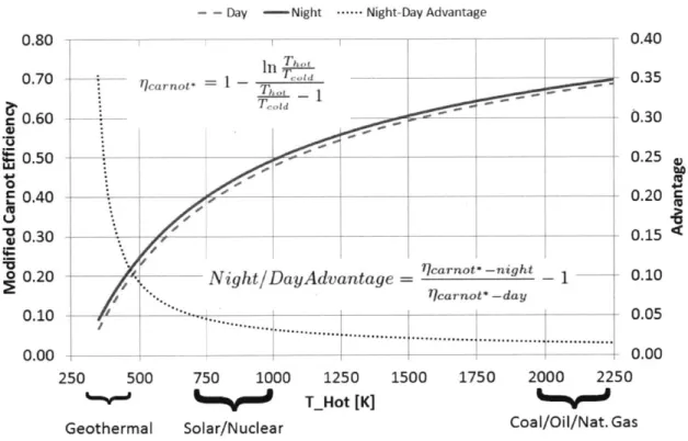
While the quality of a power plant's heat source influences working fluid selection, cycle configuration and the system efficiency, the method of heat rejection also has a notable effect on the system performance. Even at Carnot efficiency, the heat rejection requirements of a geothermal power plant can be an order of magnitude greater than the usable power produced. Often the hot source is not a reservoir as assumed in the Carnot efficiency but rather a hot stream, e.g., the flue gases in coal plants or the brine in binary geothermal plants. In that case the theoretical limit is given by the so-called modified Carnot efficiency Figure 1-1 shows the modified Carnot efficiency versus heat source temperature for heat rejection temperatures associated with arid climate daytime and nighttime operation. The physical interpretation of this figure for Rankine cycles is that heat rejection at lower temperature allows for lower condenser operating pressure. This increases the pressure drop across the power turbine and thus the power produced.
Plants located with ready access to large bodies of water can utilize a liquid cooled condenser to employ a river or ocean as a cold sink. This method requires very little parasitic load for cooling water pumping and the footprint of heat rejection apparatus is limited to a liquid-liquid heat exchanger. The temperature of a suitably large body of water can change with the seasons, but the period of such changes is on the order
of months.
Some plant locations are remote to large bodies of water, but still have a reason-ably inexpensive water supply. Given low humidity ambient conditions, such facilities can use evaporative cooling techniques to condense to temperatures near the ambient wet bulb temperature. This temperature fluctuates with the ambient temperature and relative humidity. Evaporative cooling systems require either a higher parasitic load to drive fans and/or increased capital and footprint to erect natural draft towers. A third cooling scenario arises in arid climates where water is expensive, if not unavailable, for industrial purposes. In this case, heat rejection is accomplished by an air cooled condenser. An air cooled condenser (ACC) utilizes fans to create a draft over finned heat exchange tubes. These units tend to have a substantial footprint and can require a significant parasitic load to drive the fans. For the example system the parasitic load from the ACC fans can account for a significant portion of the gross turbine output, depending on ambient conditions. The condenser operating pressure is also highly dependent on ambient dry bulb temperature, which fluctuates significantly from night to day.
1.2
Geothermal Power
Geothermal power is a method of electricity generation that utilizes geothermal fluid heated by hot subterranean rock as a heat source. The rocks in the earth's crust are heated by a combination of residual heat from the formation of the planet and radioactive decay of several isotopes trapped in the rock. Most of the earth's surface is covered by a relatively thick layer of uninterrupted crust that serves to insulate the surface from the extreme magma temperatures found at depth. However, in some places geological formations such as fault lines and fractures in the earth's crust allow fluids such as magma or aquifer water to more efficiently carry the geothermal heat closer to the surface. In such locations a usable heat source is accessible at a reasonable drilling depth. [4]
formations, such as the example plant discussed here, are unable to directly utilize geothermal steam. Therefore, they require more complex binary cycles such as an Organic Rankine cycle or the ammonia based Kalina Cycle. Hot brine is used to vaporize a low boiling point working fluid via an evaporator. Binary cycle plants seek to make up some of the efficiency losses due to low temperature heat sources by employing recuperators and more complex flowsheets.
[4]
1.3
Motivation
This thesis focuses specifically on the challenge of improving cold sink behavior of a power station in an arid climate where evaporative cooling is impractical. Many of the world's identified geothermal resources are located in hot and dry regions such as the American southwest and their development is dependent on some form of air cooled heat rejection system.
Dry air cooled condensers are susceptible to significant performance degradation as ambient temperatures increase during the day. Because geothermal power relies on a relatively low temperature heat source the overall cycle efficiency is more sensitive to fluctuations in the cold sink temperature than other power production technologies.
Much of this capability is recovered as ambient temperatures fall during the night, but (like many renewable technologies) these performance transients do not corre-spond with fluctuations in typical demand profiles. See Figure 1-3 depicting several U.S. demand curves. Also see Figure 1-4 depicting ambient temperature and the ex-ample plant output versus time of day. Notice that as demand is rising up to a peak in early afternoon, the output of the plant is falling because the ACC's cannot reject sufficient heat to the hot ambient air. It is desirable to develop a system by which the cooler night time temperatures can be used to improve plant performance during the warmer daytime hours when demand (and therefore electricity price) is elevated.
Modified Carnot Efficiency and Day/Night Advantage Day=320C Night=170C
- - Day -Night .--- Night-Day Advantage
0.40
In
Th'")" ricarnot- = 1 - 0.35 0.30 -0.25 0.20 C 0.15Night/DayAdvantage 7carnot -night - 1 0.10
-carnot* -day
0.05 0.00
250 500 750 1000 1250 1500 1750 2000 2250
T_Hot [K]
Solar/Nuclear Coal/Oil/Nat. Gas
Figure 1-1: Modified Carnot Efficiency and Day/Night Advantage
0.80 0.70 0.60 0.50 0 0.40 'U 0.30 o 0.20 0.10 0.00 Geothermal
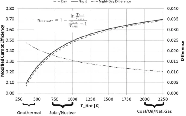
Modified Carnot Efficiency and Day/Night Difference Day=320C Night=17*C
- - Day -Night . Night-Day Difference
0.80 7 7 -In T"' o __ 0.70 ricarnot- = 1 - T e 0.60 0.50 0.40 EU 0.30.---... ~0.30 __ 0 0.20 0.10 0.00 250 500 750 1000 1250 T_Hot [K] Geothermal Solar/Nuclear 0.040 - 0.035 0.030 - 0.025 , 0.020 -- 0.015 .'""".." 0.010 _ 0.005 0.000 1500 1750 2000 2250 Coal/Oil/Nat. Gas
Average Hourly Load, PJM Mid-Atlantic Region
0 24 48 72 96 120 144 168
Hour of week
- 7/27/2009 (85 deg) - 1/5/2009 (~40 deg) - 4/6/2009 (~SS deg)
Figure 1-3: Typical Load Curves [9]
Ambient Temp and Plant Net Power 27_Jul_2011_0:0to3_Aug_2011_0:0 --- Amb_T_C_Avg -NetPowerModelMW 40 , 3-5 230 225 o 20 0L 4a-J Q) Z 15 41-A Cu fl 10 5 0
A
11 f 4-£~1411k \ Sg VV V, 208 209 210 211 212 213 214 215 Day Of YearFigure 1-4: Ambient Temperature and Net Plant Output [5]
55,000 50,000 45,000 S40,000 S3,000 30,000 25,000 20,000 0L E .T -E J'%
1.4
Objectives
The primary purpose of this thesis is to assess the potential benefits of a cold side thermal energy storage system. While a cold side thermal energy storage system is applicable to many types of power plants this thesis intends to demonstrate the value of applying one to a geothermal power plant. Geothermal power plants are uniquely dependent on geological formations that sometimes necessitate their construction in the hot, arid climates where heat rejection is difficult.
The secondary goal of this thesis is to perform a rough economic analysis, com-paring the financial benefits of implementing the proposed system to the capital costs required.
1.5
Model of Existing Plant
A cycle model of an operational geothermal power plant is employed to model the plant performance with and without a cold side TES system. The 20 MW Salt Wells facility is operated by the Italian electric utility Ente Nazionale per l'Energia eLettrica (ENEL). Salt Wells is located on a remote location in Fallon Nevada USA. The plant employs isobutane working fluid in an organic Rankine cycle and depends solely on air cooled condensers for heat rejection to the atmosphere.
Ghasemi and Mitsos [5] have developed a comprehensive pseudo steady-state model of the plants operation based on equipment specifications and operating data provided by ENEL. Their validated model of current operation is used as the baseline for this study.
For the purposes of this study only certain operating parameters and the detailed specifications of the ACCs are considered. The geothermal brine flow rate and in-coming temperature are assumed to be constant. Therefore, the gross turbine power output is dependent on the pressure that can be maintained in the condenser. Figure
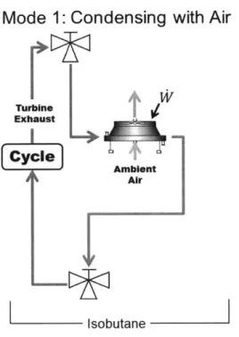
1-5 shows the effective flowsheet operating mode for the existing system as it pertains to this study. For the purposes of this study, this is called operating mode 1. The
Mode 1: Condensing with Air
Turbine Exhaust [Cyclew
I' IsobutaneFigure 1-5: Existing System Operating Mode
TES system adds two additional modes that are described in detail in subsequent sections.
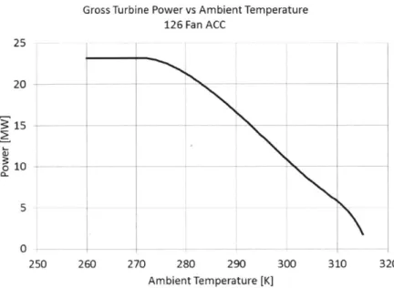
Performance curves represent the effective behavior of the complex cycle as a function of ambient temperature. Figure 1-6 relates turbine gross power to condenser pressure and Figure 1-7 shows the relationship between condenser pressure and ambi-ent temperature for the existing 126 fan ACC. The flat part of the pressure vs ambiambi-ent temperature curve is due to turbine operating limitations that require a minimum con-denser pressure of 300 kPa. These curves combine to yield the relationship between turbine gross power and ambient temperature of Figure 1-8.
One third of the ACC fans operate at a constant speed and the other two-thirds are adjustable. This allows for reduced parasitic load when the minimum condenser pressure is achieved during cold weather. Figure 1-9 shows the power required to run the 126 fan ACC unit as a function of ambient temperature.
Turbine Gross Power Output vs Condenser Pressure Salt Wells Geothermal Power Station (ENEL)
300 400 500 600
Condenser Pressure [kPa]
700 800 900
Figure 1-6: Turbine Gross Power Output vs Condenser Pressure for Salt Wells Plant [5]
Condensation Pressure vs Ambient Temperature Salt Wells 126 Fan ACC
900 800 700 .600 A 500 400 300 200 --250 260 270 280 290 300 310 320 Ambient Temperature [K]
Figure 1-7: ACC Condenser Pressure vs Ambient Temperature for 126 Fan ACC
Existing Salt Wells
25 20 3 15 0 -~10 4A 0 -200
Gross Turbine Power vs Ambient Temperature 126 Fan ACC 25 20 -10 -5 0-250 260 270 280 290 300 310 320 Ambient Temperature [K]
Figure 1-8: Turbine Gross Power Output vs Ambient Temperature for Existing Salt Wells Plant
Fan Parasitic Load vs Ambient Temperature
126 Fan ACC
42 Fans Fixed Speed, 84 Variable
2 1.5 L11 0 0.5 0 250 260 270 280 290 300 310 320 Ambient Temperature [K]
1.6
Proposed System
The proposed cold side thermal energy storage (TES) system uses a large concrete block as the thermal storage medium. Iron pipes pass through the concrete block to carry heat exchanger oil. During periods of cool ambient temperature the geothermal plant operates as usual, employing ACCs to condense the Isobutane working fluid. Meanwhile, the TES system is cooled by circulating the heat exchanger oil through an air cooled heat exchanger (ACHX) and the concrete block, thus cooling it. This is Mode 2. At a given time of day, the system switches from cooling the TES to using the TES as the cold sink (Mode 3). This is accomplished by routing the Isobutane working fluid through an oil cooled condenser (OCC) which is cooled by the TES heat exchange oil. As this operation proceeds, the TES is gradually warmed until the system is once again switched into cooling mode (Mode 2). The system is also capable of operating in mode 1, ACCs used to condense the working fluid without the TES or ACHX active, under certain circumstances.
Mode 2: Condensing with Air, Cooling TES with Air
Exhast
L Cold
[mbycne Storage -y
isobutane Heat Exchange Oil
(a) Coldside TES Cooling
Mode 3: Condensing with Oil
ht ,~,
fl
ColdiiO" Storage
isobutane Heat Exchange Oil
(b) Coldside TES Heating
Chapter 2
Procedure
2.1
TES Sizing
The sizing of the Artificial Cold Sink system has two main considerations. The first is ensuring sufficient thermal mass to store the required heating load for the desired amount of time. The second consideration is designing the pipe geometry, concrete geometry and flow rates such that the required heat exchange is accomplished with a reasonable temperature differential under design conditions. The following thermal storage capacity equation relates the heat rejection required during TES enhanced condensing with the thermal capacity of the TES block and the anticipated
temperature change of the TES block.
Capacity = Qcondensing tcondensing = Vsoiid psolid - Csoid * (T2 - T1)
The first step in assigning a design capacity is determining how long the storage medium is utilized as a cold sink between cooling sessions. For instance, the system could be designed to store cold all winter and use it all summer. Or the system could be sized to store cold overnight and expend its stores the following day. The daily and seasonal transient behavior of ambient temperature must be understood in order to make this assessment. Figure 2-1 shows the minimum and maximum daily temperatures for a full year from November 2010 to November 2011. Figures 2-2
and 2-3 show ambient temperature fluctuations at a 30 minute resolution and daily minimum and maximum temperatures for January and July 2011 respectively.
Examination of the daily minimum and maximum temperatures for one year show clear seasonal trends. Both minimum and maximum temperatures trend towards their peak in the summer months and tend to be lowest in the winter months. The separation between minimum and maximum daily temperature is most predictably large in the summer months and to a lesser extent in the autumn months. However, during the winter months the distribution becomes more erratic. Some days have
particularly high lows that could exceed the high of a few days later.
These studies show that ambient temperature drops very reliably from day to night during the warmest months. This is also when performance is most severely impacted by high daytime temperatures. A storage capacity for one day of usage is chosen in order to successfully capitalize on the predictable temperature changes of the hot months without oversizing for the unpredictable cool months.
Daily Minimum and Maximum Ambient Temperatures ENEL Saltwater Site Nov 2010 - Nov 2011
Daily_Min DaiyMax 320 310 300 . TJ 4 1~~~~4 1. *. . 4 + 290. . *.$. .. .. -. ,. ,*# ; EI~***~~-250 270 260 ;+. +. + .,~V +~t -90 -60 -30 0 30 60 90 120 150 180 210 240 270 300 330 Day_Count
Figure 2-1: 2011 Daily Minimum and Maximum Ambient Temperature at Salt Wells Plant [5]
V
Ambient Temperature Fallon NV January 2011 320 310 300 ) 290 280 - U -I .T 270 < 260 250 0 14 21 28 Day of YearDaily Minimum and Maximum Ambient Temperatures
Fallon NV January 2011 Daily_Min_K = DailyMax_K 320 310 S300 a 290 E 9280 wLU270 E260 250 15 Day of Year
(a) Ambient Temperature January 2011 (b) Daily Min
2011
and Max Temperature January
Figure 2-2: Ambient Temperature S [5] Ambient Temperature Fallon NV July 2011 182 189 196 Day of Year 203 210
(a) Ambient Temperature July 2011
tudy January 2011 Fallon Nevada
Daily Minimum and Maximum Ambient Temperatures
Fallon NV July 2011 DailyMin_K = DailyMax_K 320 2310 * ~300 290 +. 280 w 270 260 250 181 188 195 Day of Year
Figure 2-3: Ambient Temperature Study July 2011 Fallon Nevada [5] 22 29 320 s-310 300 V290 CL E 280 270 260 250 202 209
For the purposes of analyzing the impact of this technology, a relatively simple control scheme is planned. The system is allowed to use the TES as the cold sink (mode 3) for a maximum of 9 hours per day. Therefore, the required capacity is set
by the heat load imposed by condensing 425 kg/sec of Isobutane during the 9 hours
between 11am and 8pm. These hours tend to be the hottest and also correspond to the highest electrical demand and wholesale prices.
The capacity estimation assumes that the thermal storage medium starts and ends at a homogeneous temperature. This is not the case during a transient over a finite time period. The material closest to the pipe undergoes a greater temperature change than the material furthest from the pipes. In order to roughly compensate for this the proposed system is over-sized by designing it for 12 hours of capacity. This assumption may result in a TES with excess storage capacity. In this case, a finding of insufficient system performance is that much more significant.
The operating pressure of isobutane in the condenser ranges from 300 to approxi-mately 850 kPa with the corresponding cold sink heating rate between 132 MW and
151 MW. For sizing purposes an intermediate value of 142 MW is assumed. Concrete
is the chosen storage medium and an allowable temperature change of approximately 10K is assumed based on allowable performance rollback with increased oil temper-ature. The results of the required storage volume calculation are shown in Table
2.1. Qcondensing 142 MW time 12 hrs T2 - T1 10K Pconcrete 2300-3 Cconcrete 9 6 0kg Vconcrete 279,000 m3
Table 2.1: TES Rough Sizing
With the concrete volume established, the effects of the detailed geometry are studied. A brute force method is employed to analyze the performance impact of pipe diameter, pipe length and flow Reynolds number. Parametric sweeps are performed
Required Heat Rejection vs Condenser Pressure 425 kg/sec of Isobutane 155 150 145 W 140 4S 135 130 -200 300 400 500 600 700 800 900 Condenser Pressure [kPa]
Figure 2-4: Cooling Load Required to Condense 425 kg/sec of Isobutane
over pipe diameters between 1 cm and 1 m, pipe lengths from 250 m to 5 km and Reynolds numbers from 250 and 25,000. All sweeps are performed assuming an oil mass flow rate of 10,000 kg/sec. The following calculations are performed for each combination of these variables as follows.
The flow properties for each pipe and flow configuration are established for can-didate Reynolds numbers and pipe diameters. The required pipe count is then estab-lished based on the mass flow rate through each individual pipe.
Rey - pDh moil-pipe pvoii-Dh S oil-total npipes~ h~ oil-pipe
For preliminary sizing, all fluid properties are taken at 310 K because this is near the expected maximum operating temperature. The oil viscosity decreases with temperature. Therefore, the oil mean velocity decreases and required pipe count increases with increasing fluid temperature at a fixed Reynolds number. Material property curves may be found in the appendix.
Internal laminar flow Re < 2300 [3, p761] 64 f R ReD Nu = 1.86. Re-Pr -Lpipe
Internal Transition Flow 2100 < Re < 104
Darcy friction factor for transition flow assumed to follow turbulent equation:
f = (0.790 -In ReD -1.64) -2
Nu = 1.116 -
(Rei
- 125) Pr / 0.14 - 1
+(
Dh
3Lpipe
Internal turbulent flow 104 < Re < 5 -106 [3, p761]
f = (0.790 - ln ReD - 1.64 2
Nu =
(j
(ReD 8 - 1000) Pr 1 + 12.7(j)
- (PriCalculation of convective heat transfer coefficient between fluid bulk temperature and wall temperature:
Nuk c =Dh
Calculation of concrete dimensions:
Ascid = Vconcrete
Lpipenpipes
4A01hd Do = 4Asi h
The average difference between the fluid bulk temperature and the pipe wall tem-perature is a function of the operating TES oil flow rate, the solid and oil heat capacities and the transient characteristics of the whole system. Analysis of the
tran-3 0. 14
sient AT = Tflid - T8o0 i is too complex to be useful during initial sizing. However, a
minimum required AT is easily calculated as a function of the required temperature drop across the axial length of each pipe: ATaxiai. This temperature drop is equal to the temperature drop across the oil cooled condenser, which is a function of the total oil mass flow and the condenser average operating pressure.
ATaxia lilisobutanehfg-avg-isobutane liloil -total Cpoil
8T _ATaxial
Ox Lpipe
The AT is calculated once using the convective heat transfer coefficient, c, to de-termine the temperature difference between the liquid bulk and wall surface tempera-ture and once using the combined convective and conductive heat transfer coefficient
U for the required difference between the liquid bulk and solid bulk temperature.
ATVoilPCPO D2 hD ATon Poi 4 nh7Dh ,VoilpC, D U7rD
The local Biot number is used as an indicator of the transient behavior of the concrete. This local Biot number is calculated for a planar section of the pipe cut perpendicular to the axis.
Lc = Across-section
-rDh hLc
Bi = k
The required oil pumping power is estimated as a function of the oil volumetric flow rate and the pressure drop across the TES unit. The actual simulation tracks the pumping power as a function of the volumetric flow rate and the pressure drop across both the TES and the ACHX.
9p f -pV 1 BI 2D2 (p Appipe = -Lpipe Voil-totai -ioil-total Poil WTESPump Voil-totalAppipe
The capital cost of a given configuration is estimated by the cost of the concrete and iron pipes required to build it. For these purposes a concrete cost of $50 per cubic meter and an iron cost of $400 per ton.
[2]
The following equation is used to relate pipe thickness to its diameter. The ac-tual thickness of the metallic pipe is variable. This exponential relationship between diameter and pipe wall thickness is intended to represent the increased wall thickness likely required for a larger pipe diameter. While the thickness values are close to the expected values of actual pipes that may be used, it is more important to capture the expected trend of sub-linear thickness increase with pipe diameter increase. This tries to ensure that competing potential configurations with different pipe diameters are not unjustly penalized by assuming a constant or linear wall thickness.
thkpipewani 0.01D0
The cross section and required iron mass of a given iron pipe configuration is calculated with diameter and wall thickness.
Apipewan = ((Dh + thkpipewai) - Dh)
miron =ApipewainpipesLpipespiron
CC = Vconcrete -MPconcrete + miron -MPiron
Test configurations are chosen for comparison trials based on the lowest cost con-figuration that satisfies certain constraints on ATh , Woilpump and Bi. Comparison
between several potential configurations yielded the following configuration.
2.2
TES Simulation with COMSOL® Multiphysics
The concrete thermal storage block is simulated by a 2D axi-symetric model in COM-SOL Multiphysics @ Version 4.2a.
[1]
The model utilizes the Heat Transfer in Fluids module with Heat Transfer in Solids added to the simulation to represent the concrete. The model geometry consists of two concentric cylinders; the inner representing the fluid domain and the outer the solid.Heat exchanger oil flows in one direction when the system is cooling the concrete block and the opposite direction when the concrete block is being used as the cold sink. One end of the block is designated as the hot side and one is the cold side. When the TES is used to cool the OCC (mode 3), hot oil at OCC exit temperature enters the hot side, flows through the block and exits the cold side. The bulk temperature at the cold side exit is calculated by COMSOL and is passed to the main program as the OCC inlet temperature. Conversely, when the ACHX is active (mode 2) the TES oil flows from the cold side towards the hot side. The bulk temperature at the hot side exit is the inlet temperature of the ACHX.
The outer surface of the concrete is modeled as insulated. In reality this surface is in contact with the adjacent pipe/concrete pairs. The insulation boundary condition acts to enforce the symmetry present in such a configuration.
Built in material properties for heat exchanger oil and concrete are utilized. The built in material properties are described in detail in Section 2.5.3. The built in con-crete model requires a user defined specific heat capacity. This is set to a constant CPconcrete = 960 kg. The oil density for the built in model is a function of
temper-ature. Conservation of mass and the assumption of a constant velocity distribution necessitates a constant density of pai = 8753.
COMSOL has some difficulty efficiently modeling turbulent flow. The primary
purpose of the transient simulation is to simulate the heat transfer from the TES fluid to the TES thermal storage medium. Fluid mechanics effects such as the pressure drop
along the pipe length are secondary and are adequately approximated with literature equations. Therefore, solution of the Navier-Stokes equations is ignored and the oil is modeled as constant velocity plug flow.
Lizarraga-Garcia and Mitsos have developed a technique by which turbulent heat transfer is accurately modeled in COMSOL using fixed velocity plug flow. [7] In order to ensure appropriate heat transfer characteristics in this regime, the value of the convective heat transfer coefficient, c, is matched to literature values. To accomplish this a control volume is built into a test model. For a given geometry and Reynolds number, the test model is configured to the appropriate dimensions and flow velocity and run through an example cooling cycle. The COMSOL integral tool is utilized to sum the energy flowing into and out of the control volume. The effective convective heat transfer coefficient is determined from the net heat flux with the wall and the average control volume wall temperature. For each configuration tested the oil thermal conductivity is adjusted such that the effective thermal conductivity in the fluid appropriately represents the effective thermal conductivity in a turbulent flow. This yields an ceffective that matches the literature value for the convective heat transfer coefficient.
ceffectiveoil-in - oi-out
cDhLcv (Tbuik-oii-cv - Twaii)
2.2.1
Metallic Pipes in TES Storage Block
The presumed metallic pipes necessary in the actual system are not modeled in COM-SOL. The radial thermal resistance of such pipes is insignificant in comparison to the thermal resistance of the much thicker concrete that has a much lower thermal con-ductivity. See example calculations below.
In Douter
~Dinner Rcylinder-conduction = k2ir
Dhpipe 0.66 m thkpipe .011 m Douter concrete 1.155 m kconcrete 1.8W kiron 80 Riron-pipe 6.52e-05m Rconcrete 4.66e-02 m
Table 2.2: Radial Pipe Resistance Comparison
the iron pipe and the concrete are of the same order of magnitude as the concrete alone. This indicates that the overall axial conduction rate is not largely affected by the presence or absence of the metallic pipe material. Therefore, it is assumed that
the iron pipes may be neglected in the COMSOL analysis.
2.2.2
Mesh Density Studies
The density of the finite element mesh must be sufficient to preclude any adverse affects on the analysis. For example, if the mesh is too coarse the transient accuracy is diminished and if the mesh is too fine the analysis takes an unnecessarily long time to run. For this analysis, increased simulation speed is only pursued if it does not adversely affect accuracy.
In order to set the model mesh density a simulated 24 hour test run is used to exercise several potential mesh configurations. The test run includes both rapid and slow transient elements from 1 hour duration to 8 hours duration and it varies the inlet temperature over a range of 20 K. This closely approximates the transients that occur under operating conditions.
First the radial mesh density is studied. A very fine axial mesh is established with axial nodes 0.25 m apart along a 5000 m pipe length. The first axial mesh configuration has two elements through the concrete thickness and two from the pipe wall to the fluid center (axis of the pipe). The example transient run is executed and the outlet temperature at 24 hours is recorded. This process is repeated with 3+3 radial elements, 4+4 radial elements and so on until the final temperature is seen to
change less than 0.0025% for each additional element. The final radial mesh density is set to 6 elements through the concrete and 6 from the pipe wall to the center of the fluid.
Next the axial mesh density is examined. The 6+6 radial mesh is maintained and the first test is run for a slightly more coarse axial mesh than was used for the radial study. The axial element size is increased until doubling the element size is found to change the final outlet temperature by greater than 0.0025%. The axial element length is set to 25 m. This corresponds to 200 elements along the length of a 5000 m pipe. For this element length the outlet temperature after the 24 hour test run differs by 0.0031% with respect to a 0.25 m element size.
2.3
Matlab® with COMSOL Livelink®
The air cooled condensers, oil cooled condensers and oil pump may be modeled as pseudo-steady-state. Justification for this assumption is provided for each component in Section 2.4.1. The governing equations and lookup tables for their operation are modeled as Matlab functions. These functions are called as Matlab steps through simulated operation of the heat rejection and TES components at pre-defined time step intervals. Unless otherwise specified studies described are run with a 30 minute time step size.
The code is setup to run from a given start time expressed as the second of the year with zero as midnight on January 1st 2011. All of the component models are initialized to starting conditions based on the average temperature of the previous 24 hours.
At the beginning of each time step a lookup table provides the instantaneous ambient temperature. Control logic uses the ambient temperature, TES block state and the time of day to determine what operating mode should be executed. Next fan powers, pump powers, condenser pressure, turbine output and oil temperature changes are calculated using the associated Matlab functions for the given operating parameters and ambient temperature. The corresponding TES oil input temperature
is then established and finally Matlab calls COMSOL to run the TES block for a duration of one time step. The oil outgoing temperature at the end of the time step is then stored and used as the starting point for the following time step. This process continues until the desired simulation time is achieved.
2.3.1
Ambient Temperature Data
Ambient temperature as a function of time is the only required input for the sys-tem model. Fallon Nevada historical observations at 30 minute intervals are used to initialize the starting temperature of the TES and by the ACC and ACHX Matlab functions to set the incoming air temperature of the air-cooled heat exchange simu-lations. The simulation is only allowed to use weather data from the current time or previous time steps. The system is not allowed the benefit of weather predictions.
The effects of wind conditions, cloud cover, humidity and precipitation are ne-glected.
2.3.2
Operating Mode Logic
The simulation code has three primary operating modes as described in Section 1.6. The operating mode selection is made at the beginning of each time step and is based on the time of day, the TES state and a comparison between the potential power produced in potential modes. See Figure 2-5 for visual representation of the decision process.
The first consideration in the operating mode decision is the time of day. The TES is only allowed to act as a cold sink during the hours between 11am and 8pm. Between 11am and 8pm the system defaults to mode 3, condensing in the OCC with the TES as the eventual cold sink. At the beginning of each time step the potential net power generation from the OCC condensing (mode 3) and the ACC condensing (mode 1) are compared based on ambient temperature and the state of the TES block. If the net power generation from mode 1 is greater than mode 3 then the system switches to either mode 1 or 2.
Key
Mode1 = ACC Condensing
Mode 2 = ACC Condensing and ACHX Cooling TES *Mode 3 =0CC Condensing with YES Cooled Oil
Figure 2-5: Operating Mode Decision Tree
The decision between mode 1, condensing with ACC or mode 2, condensing with the ACC and cooling the TES block with the ACHX is also made in regard to the ambient temperature and the TES state. The ACHX only runs when it is assumed to be providing more benefit to the system than it costs in parasitic load. As a rule for this analysis the ACHX is considered to be providing more benefit than it costs to run when the ambient temperature is at least 5 K lower than the TES block hot side discharge temperature. This rule is explained further in the ACHX design section.
The system is not allowed to re-enter mode 3 once it has switched from mode 3 to mode 1 in a given day. It is expected that this change in operating regime would require operator intervention and that it would be unreasonable to switch back and forth multiple times per day.
If the time step starts outside the 11am-8pm window, then the system defaults to mode 2, condensing with the ACC and cooling the TES block with the ACHX. Once again, mode 1 is employed as an alternative to mode 2 when the ambient temperature is not at least 5 K cooler than the TES block hot side discharge. In this case there is no potential to cool the TES and the ACHX is switched off to prevent unnecessary parasitic load.
It is recognized that this is likely not the optimal operating regime for a system of this type. It is the purpose of this thesis to estimate the benefits and costs of such
a system. A simplified control system is sufficient to determine gross trends.
2.4
Non-TES Heat Exchange Components
Simu-lation and Design
2.4.1
Pseudo Steady-State Assumption for Condensers and
Heat Exchangers
Before the details of the ACC, OCC and ACHX simulation are developed, it must be established that operation of these components may be modeled as pseudo steady-state. In order to understand the transient behavior of the pipes and casings of the heat exchangers, their heat exchange duty is compared to the rate of heat absorption under a typical step change in incoming fluid temperature. The condenser duty and temperature rate of change are calculated from 2011 operational data provided by ENEL.
Qcondenserduty rhC4H10AhC4H1O
The 2011 data shows an average Qcondenserduty =133MW
The rate of heat absorption into the pipes and casing of the heat exchange equip-ment of the condenser is
BE B
OE_ -mequjpment Cp a
8t equipment at
From ACC specifications: Steel ACC pipes
Mpipes =445, 000kg
Csteei = 500 kgK Aluminum Fins
Cauminum = 900
kgK
Under an average transient ATiet is .0004 2
}
. This results in an energy absorptionAt S
rate of
BE
__ 4.5MW
at
equipmentThis corresponds to about 3.5% of the heat exchange duty.
An extreme transient is modeled by the mean plus 3 sigma A§2At net" of .00245jK S for
2011. This results in an energy absorption rate of
BE
= 26MW Ot equipment
This corresponds to about 20% of the heat exchange duty.
Under normal operating conditions the equipment absorbs or rejects (depending on the direction of transient) energy at about 3.5% of it's intended heat exchange duty to equilibrate to the fluid temperature. Since this energy remains in the system it will act as a sort of time delay. Since the magnitude of the energy stored vs the overall heat duty is generally small, the effect on the transient behavior of the plant operation is negligible.
The ACHX is assumed to have the same geometry as the ACC. The OCC has a significantly smaller mass than the ACC, as it is a liquid cooled condenser and, as such, requires less surface area. Therefore the OCC is even closer to pseudo steady-state than the ACC and ACHX. The ACC, ACHX and OCC are modeled as steady-state.
2.4.2
Air Cooled Condenser Simulation
The Salt Wells ACC units are an induced draft cross flow configuration. The fluid pipes are arranged in five rows of two passes per row. The pipes are arranged such that the hot fluid enters at the topmost row where the passing air has been heated by the lower rows. This is modeled as a discretized counter flow heat exchanger with N nodes and N-i discrete sections. The first node corresponds to isobutane entering the ACC and air exiting. The discrete simulation proceeds one section at a time until
the last node where the isobutane exits the ACC and the air enters. The simulation of the ACC counterflow heat exchange is modeled with a forward differences method. The heat exchange in each discrete section is governed by the following equations.
The heat exchange in each section is calculated by the isobutane-air temperature difference at the section node corresponsing to the isobutane inlet. The isobutane enthalpy is then calculated based on the incoming enthalpy, the section heat exchange and the mass flow rate. The outgoing isobutane enthalpy is then used to determine the outgoing isobutane phase and temperature. The change in air temperature across the section is calculated under the assumption that the air is always in the gaseous phase. Note that the air temperature at node n+i is a smaller value than at n. This
is because the air is flowing in the opposite direction as the isobutane.
Qsection
- dA -U -(Tisobutane - Tair)hisobutanen+i = hisobutanen + Qsection
misobutane
f
(h, p) if hisobutanen+ > hvsatTisobutanen+
f
(h) ifhisobutanen+1 < hfTsat otherwise
T air= Tairn aQsection
a 1CPair (Taira
The ultimate purpose of simulating the ACC operation is to determine the isobu-tane pressure that can be sustained as a function of ambient temperature. A pair of nested bisection loops are employed to determine this pressure for a given ambient temperature. The correct operating pressure is achieved when the isobutane exits the ACC at 1K below the saturation temperature.
Two bisection loops are necessary because both the condenser pressure and the corresponding air outlet temperature are unknown. The outer loop bisects between the maximum and minimum pressures of 1000 kPa and 300 kPa respectively. These
values are chosen as they bracket pressures reasonable accomplished with expected ambient temperatures in the range of 260K - 315K. The inner bisection loop solves for the air exit temperature by bisecting between an upper limit of the isobutane inlet temperature and a lower limit of the air inlet temperature.
Bisection is not the most efficient numerical scheme to identify the condenser pres-sure and appropriate air exit temperature. However, bisection always converges to the correct value for monotonic functions. The level of subcooling varies monotonically with the condenser pressure for a given cooling capacity and the air inlet tempera-ture varies monotonically with air exit temperatempera-ture for a given condenser pressure and heat exchange duty.
Solving for the correct operation at a given ambient temperature begins by sim-ulating the ACC operation at the average of the minimum and maximum pressures. The isobutane is assumed to always enter the ACC at 10K above saturation temper-ature. The bisection starting value for the air exit temperature is calculated based on the average of the isobutane and air inlet temperatures. Then the forward differences simulation of the ACC is carried out across it's effective length. If the corresponding air inlet temperature is found to differ from ambient by more than a certain tolerance, the bisection limits are moved and the simulation is repeated until the simulated air inlet matches ambient within tolerance. When this is achieved the subcooling level of the exiting isobutane is compared to the target subcooling level of 1K. If the trial subcooling level differs from the desired 1K subcooling by more than an allowable tolerance the bisection limits are adjusted and this process is repeated until the pre-scribed 1K of subcooling is achieved.
The effective heat transfer coefficient, U, is an integral part of the forward differ-ences condensation simulation. The value of U is a function of the heat exchanger geometry, air flow rate, isobutane flow rate and whether the heat exchange is from va-por to air, two-phase to air or liquid to air. The first step in this process is calculation of the air flow rate based on an assumed fan speed and the ambient air temperature and density. This air flow rate is then used to calculate a convective heat exchange coefficient for the air side heat transfer. The liquid side convective heat exchange
co-efficients are functions of the isobutane mass flow rate and the flow regime. Finally, the two convective heat transfer coefficients are combined with a constant conduction resistance to yield U.
A byproduct of the ACC operation is the parasitic load induced on the system by the operation of the ACC fans. The power consumption of these fans depends on the selected configuration and the fan speed at any given condition. For example, the
existing example plant utilizes an ACC configuration with 126 fans. One-third of the fans operate at a fixed speed and the remaining two-thirds have variable speed drives. The fans operate at maximum power unless the ACC has reached the minimum operating pressure of 300 kPa. In this case the variable speed fans are slowed until they provide just enough airflow (and thus heat transfer coefficient) to accomplish the condensation.
The equations used to calculate the convective fan power consumption, heat trans-fer coefficients and effective U value are based on curves and studies provided by the ACC manufacturer for the specific example plant application. Their implementation for this thesis is unique to this study, but a more detailed examination of the manu-facturer curves and their relationship with traditional literature heat exchange values is examined by Ghasemi and Mitsos.
[5]
The effects of the isobutane pressure drop across the ACC are ignored. Both the standard configuration and the TES enhanced configuration would have the same pumping loads when the ACC is in service. The OCC is likely to have different pres-sure drop characteristics than the ACC, but these loads are assumed to be negligible considering the low mass flow rate of the isobutane and the fact that these systems are specifically designed for the application.
2.4.3
ACC Fan Count
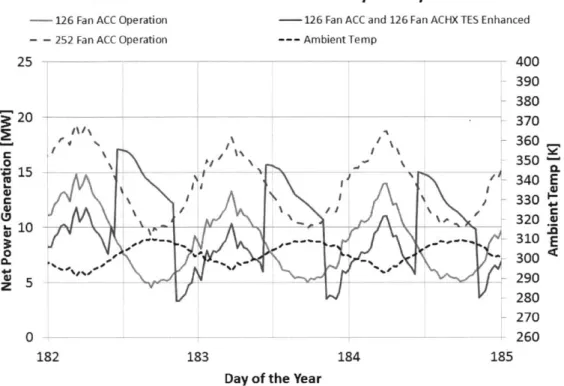
The existing Salt Wells facility utilizes a 126 fan ACC but herein 252 fans are used as the base case for a more fair comparison. Preliminary simulations of the TES enhanced system are run with a 126 fan ACC and a 126 fan ACHX. Figure 2-6 shows a net power comparison between 126 fan ACC system and a 252 fan ACC system.
Net Power Generation - First Three Days of July 2011
- 126 Fan ACC Operation -126 Fan ACC and 126 Fan ACHX TES Enhanced
-- 252 Fan ACC Operation --- AmbientTemp
25 400 390 380 20 370 360, 350 15 - --- - - 4 - - - -- 340 E 03330 280 270 0 -260 182 183 184 185
Day of the Year
Figure 2-6: Net Power Generation for 126 Fan and 252 Fan ACC Configurations
These preliminary simulations show a dramatic energy production increase for the TES enhanced system with 126 fan ACC and a 126 fan ACHX. However, this seems to be largely due to the increased cooling capability provided by the 126 fan ACHX. Comparison to a modified configuration with a 252 fan ACC and no TES shows that the facility produces even more energy when the 126 ACHX fans are instead applied directly to cooling the ACC.
The ACC must be properly sized for summer operation in order to demonstrate the benefits of a TES enhanced system. Therefore, a modified plant model with a 252 fan ACC is adopted for comparison to the TES enhanced system. The TES enhanced air cooled heat exchangers include a 252 fan ACC and a 252 fan ACHX.
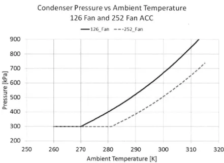
Figures 2-7, 2-8 and 2-9 show the Condenser Pressure, Turbine Gross Power and Fan Parasitic Load curves versus ambient temperature for a 126 fan ACC and a 252 Fan ACC.
Condenser Pressure vs Ambient Temperature
126 Fan and 252 Fan ACC
-126_Fan --- 252_Fan -o
JI
300 200 -250 260 270 280 290 300 310 320 Ambient Temperature [K]Figure 2-7: ACC Condenser Pressure vs Ambient Temperature Fan ACC Configurations
for 126 Fan and 252
Fan Parasitic Load vs Ambient Temperature
126 Fan and 252 Fan ACC 1/3 Fans Fixed Speed, 2/3 Variable
-126_Fan --- 252 Fan 2 1.5 1 0 0.5 I 'a -a- - - - -0 -250 260 270 280 290 300 310 320 Ambient Temperature [K]
Figure 2-8: Turbine Gross Power Output vs Ambient Temperature 252 Fan ACC Configurations
for 126 Fan and
900 800 700 CL 600 500 400
![Figure 1-6: Turbine Gross Power Output vs Condenser Pressure for Salt Wells Plant [5]](https://thumb-eu.123doks.com/thumbv2/123doknet/14362256.502824/27.918.222.664.154.468/figure-turbine-gross-power-output-condenser-pressure-wells.webp)
![Figure 2-1: 2011 Daily Minimum and Maximum Ambient Temperature at Salt Wells Plant [5]](https://thumb-eu.123doks.com/thumbv2/123doknet/14362256.502824/32.918.158.737.621.992/figure-daily-minimum-maximum-ambient-temperature-wells-plant.webp)