HAL Id: hal-01218787
https://hal.archives-ouvertes.fr/hal-01218787
Submitted on 22 Oct 2015
HAL is a multi-disciplinary open access
archive for the deposit and dissemination of
sci-entific research documents, whether they are
pub-lished or not. The documents may come from
teaching and research institutions in France or
abroad, or from public or private research centers.
L’archive ouverte pluridisciplinaire HAL, est
destinée au dépôt et à la diffusion de documents
scientifiques de niveau recherche, publiés ou non,
émanant des établissements d’enseignement et de
recherche français ou étrangers, des laboratoires
publics ou privés.
Using Rotation for Steerable Needle Detection in 3D
Color-Doppler Ultrasound Images
Paul Mignon, Philippe Poignet, Jocelyne Troccaz
To cite this version:
Paul Mignon, Philippe Poignet, Jocelyne Troccaz. Using Rotation for Steerable Needle Detection in
3D Color-Doppler Ultrasound Images. EMBC: Engineering in Medicine and Biology Conference, Aug
2015, Milano, Italy. pp.1544-1547, �10.1109/EMBC.2015.7318666�. �hal-01218787�
Using Rotation for Steerable Needle Detection in 3D Color-Doppler
Ultrasound Images*
Paul Mignon
1,2, Philippe Poignet
2and Jocelyne Troccaz
1Abstract— This paper demonstrates a new way to detect needles in 3D color-Doppler volumes of biological tissues. It uses rotation to generate vibrations of a needle using an existing robotic brachytherapy system. The results of our detection for color-Doppler and B-Mode ultrasound are compared to a needle location reference given by robot odometry and robot ultrasound calibration. Average errors between detection and reference are 5.8 mm on needle tip for B-Mode images and 2.17 mm for color-Doppler images. These results show that color-Doppler imaging leads to more robust needle detection in noisy environment with poor needle visibility or when needle interacts with other objects.
I. INTRODUCTION
Accuracy during needle based clinical procedures may be critical for both patient safety and operation success. Unfor-tunately, needle flexibility and variable stiffness of biological tissue intrinsically limit this accuracy. Handling capabilities and visual feedback issues faced by clinicians also make the gesture potentially inaccurate and/or unsuccessful. This has motivated a large amount of research about robotized needle insertion. Among them, needle steering - i.e. the fine control of needle curvature for the execution of curved trajectories toward a target - has received increasing interest. Indeed, needle steering also provides other clinical benefits in needle-involved procedures like obstacle avoidance or target movement compensation. Some prototypes (see [1] and [2]) use two degrees of freedom (DoFs) robots to insert and rotate the needle. They are efficient to steer needles but are not designed to fit clinical needs yet. In [3], a more complex brachytherapy robotic system was developed but did not integrate needle steering. Robotic devices are generally assisted by medical imaging, mainly ultrasound (US) [3], CT-scan [4] or MRI [5].
We previously developed a brachytherapy robot prototype called PROSPER [6] used for needle insertion and seed positioning under 3D US guidance. The robot offers six DoFs for the end-effector provided by seven motors : five of them, arranged in the positioning module, are used to orient the needle and to position its tip on a plane outside the patient. The two others, corresponding to the insertion module, are used to insert and rotate the needle inside tissue toward a predefined target. Once the needle is positioned, surgeons can easily insert seeds thanks to the needle hollow as usually
*This work was partly supported by the French ANR within the In-vestissements d’Avenir program (Labex CAMI) under reference ANR-11-LABX-0004.
1UJF-Grenoble 1 / CNRS / TIMC-IMAG UMR 5525, Grenoble, F-38041, France.
2University Montpellier II, LIRMM, 161 rue Ada, 34095 Montpellier, France
done in brachytherapy. To compensate for target movements due to prostate motion and deformation, the needle can move forward or backward based on 3D US image registration [7]. Experimental data showed that the average error between target and seed position was reduced to approximately 3 mm [6]. In order to improve its accuracy, the next step is to give this robot needle steering capabilities. This requires the capacity to accurately detect the needle from images.
US imaging has several benefits such as low-cost, simplic-ity of use, safety for both patients and clinicians. However, US imaging suffers from a lack of quality intrinsically due to the acoustic properties causing different types of image artifacts and speckle noise. This makes US images difficult to be processed.
In [8], a curved needle was segmented in 2D US imaging. In the context of 3D images, two main types of techniques exist. The first one involves processing 3D volume projec-tions on several planes using as instance Radon transform [9]. Projections are then processed with 2D algorithms. The sec-ond type of methods consists in scanning directly the entire volume. In [10], they suggested to use 3D Hough transform to detect straight lines in a volume. In [11], Uhercik used a Random Sample Consensus (RANSAC) algorithm to find 3D polynomial shapes. This method seems to be robust to noise or artifacts and can achieve relatively fast detection.
This paper focuses on the evaluation of needle segmenta-tion in 3D color-Doppler volumes compared to the segmen-tation in 3D B-Mode volumes. We consider two biological tissues : beef liver and pork tenderloins. Let us stress the fact that the aim of this paper is to analyze segmentation accuracy, not to compute needle curvature. Thus, it concentrates on straight trajectories.
We propose to apply a RANSAC algorithm to color-Doppler imaging in order to make it more robust to image noise and artifacts. Color-Doppler is mostly used to detect blood flow and is visualized by coloring B-Mode images. Needle vibrations are necessary to make the needle visible on color-Doppler imaging. In our system the vibrations simply result from needle rotation.
II. MATERIALS AND METHODS A. Color-Doppler and needle rotation
Very often, needles are difficult to detect in US images. This may come from large echogenicity of biological tissue around the needle, poor acoustic transmission, bad needle orientation with respect to transmitters or presence of objects (other needles, seeds, anatomical structures, etc. As men-tioned before, color-Doppler imaging associated with needle
rotation can be used to get a useful visual feedback. For that purpose, we used an Ultrasonix RP with endorectal end-fire probe with a convex mechanical 3D transducer and a central frequency of 6 MHz. The 3D volume results from 115 sweeps captured at angular increment of approximately 0.8°and leads to a voxel size of 0.4 mm3.
The objective being to isolate the needle from other objects, Fronheiser in [12] uses a low frequency ultrasound buzzer to create these vibrations. This configuration needs either to instrument the needle or to equip the robot, in-creasing the difficulty to sterilize the device for clinical use. Another complication with needle base instrumentation is the damping of vibration magnitude along the needle. The needle is therefore more visible near the entrance but less at the tip, specially in deeper insertions, as discussed in [13].
To prevent those limitations, we used intrinsic vibrations based on needle rotation in tissue to make the needle visible in color-Doppler images. We assume that the vibrations are caused by the needle’s slight asymmetry and the needle/robot connection slight eccentricity. Thus, they spread through the entire needle and are not only localized at its base.
B. Needle segmentation
Needle detection was achieved with a random sample consensus algorithm as described in [11]. It is based on four main steps. The first step is a fast thresholding of the image in order to keep only a specific percentage of the brightest voxels (needle is mostly brighter than the rest of the image). This percentage depends on tissue echogenicity. In the experiments (see III), a value of 1 % was used for all B-Mode images. It permitted, in our imaging conditions, to keep the entire needle shape while rejecting the maximum of medium artifacts. In the second step, a specific number of voxels are randomly selected from the voxel cloud resulting from the image thresholding. A polynomial Bezier curve is fitted to these random voxels. The random voxel number is limited by a lowest value depending on Bezier curve order. In our experiments, first order Bezier curves were used, thus the number of random voxels was set to 2. Finally, all the thresholded voxels are separated in inliers (supposed to belong to the fitted curve) and outliers. The separation criterion is a threshold on an approximation of the distance between voxels and the curve according to [11]. The three last steps are repeated and the best result in terms of number of inliers is returned. Fifty iterations were computed to optimize both computation time and result accuracy.
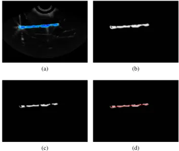
This algorithm can be applied to 2D or 3D images as well as grey scale or RGB images by adapting the first threshold-ing step. To segment color-Doppler volume, we transform RGB channels to HSV and use only the hue channel to compute RANSAC. As color-Doppler may create a blob around the needle, a morphological erosion is applied on the acquired volumes. The operator also reduces artifacts that can interfere with the needle shape. The image processing pipeline is shown in fig. 1.
(a) (b)
(c) (d)
Fig. 1. Steps of color-Doppler segmentation in a 2D image: (a) initial image, (b) extracted hue channel, (c) morphological erosion, (d) RANSAC needle location result.
This segmentation process was applied on four B-Mode 3D US images and four 3D color-Doppler images. For each modality, two images correspond to bovine liver and the two others correspond to pork tenderloin. These configurations give several interesting conditions in terms of needle visibil-ity and artifact interaction. For each image, the segmentation algorithm was run 100 times in order to test its repeatability and accuracy.
C. Needle reference
As needle position is robotically planned, a priori knowl-edge is available to limit the region of interest, allowing to reduce computation and improve segmentation precision. We computed a volume of interest using robot odometry and robot US calibration [6]. It consists of a box of 40 × 40 × Lins mm3 where Lins is the insertion distance plus
an arbitrary margin of 10 mm. It also permitted to keep an uncertainty on the needle location to test our algorithm.
The calibration between the US probe and the robot allows to compute the theoretical location of the needle in US images. It supposes that the needle did not bend during the insertion.
A standard non-beveled brachytherapy needle (diameter = 17 gauges = 1.15 mm) was inserted in the meat pieces with 5 rotations per second (rps) rotation speed and 1 mm/s insertion speed. The needle diameter and the rotation/insertion ratio imply that the resulting needle location is a straight line. Thus the segmentation detects 1storder Bezier curves. Indeed
hav-ing a curved needle would make the reference measurement inaccurate since it would rely on manual segmentation.
The errors presented in III were the average error along the axis, the error at needle tip, and the angular error in needle orientation. The first error corresponds to the mean of the distances between segmented needle points and their projections on the needle reference. The second error is the
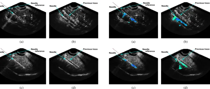
Needle Needle reference (a) Needle Previous trace (b) Needle Needle reference (c) Needle Previous trace (d)
Fig. 2. Needle in B-Mode US images in (a), (b) beef liver and (c), (d) pork tenderloin. The needle reference position given by robot odometry is displayed with a dotted line.
distance between segmented tip and reference tip. The last error is the angle between the segmented needle axis and the reference axis.
III. RESULTS A. 3D B-Mode
As mentioned in II, the results of the hundred segmenta-tions on two different volumes of each biological tissue (beef and pork, leading to a total of four hundred segmentations) were compared to the reference needle locations. Fig. 2 rep-resents liver and pork B-Mode volumes. Needle references are displayed in 2a and 2c .
In fig. 2a the needle is not clearly discernible and in fig. 2b or 2d, as the needle was inserted twice, trace of previous insertion is also visible in the volume. It leads to many false detections for these three volumes. In the first pork image (fig. 2c) the needle appears distinctly and was inserted once, providing better results. All detections (false and correct) are presented in table I.
A detection is said ”false” if the error between the ref-erence and the segmented needle is greater than 3 mm at needle tip and 10 ° in needle orientation. These values were selected based on expert advice.
False detections are reported in table I and occurred in 44 % and 48 % of the segmentations in beef volumes (2a, 2b) and in 26 % in pork volume with previous needle trace (2d). No false detections occurred in the other pork volume (2c). This results in an average error around 7 mm along needle axis and a very large average error (18 °or 12°) in needle orientation in three of the four images. This shows that segmentation accuracy is influenced by image quality or presence of other objects.
Needle Needle reference (a) Needle Previous trace (b) Needle Needle reference (c) Needle Previous trace (d)
Fig. 3. Needle in color-Doppler US images in (a), (b) beef liver and (c), (d) pork tenderloin. The needle reference position given by robot odometry is displayed with a dotted line and a rotation of 8 RPS.
In the first pork volume, the needle is clearly visible and undisturbed by previous insertions traces. The needle is thus accurately segmented, leading to an average error along the needle of 0.8 mm, 1.5 mm at the needle tip and only 2.9 ° in needle orientation.
B. 3D color-Doppler
The needle appearance in color-Doppler images depends on the needle rotation speed. We tested different speeds between 0 and 13 rps (robot maximum rotation speed). We noticed that the needle becomes visible at 3-4 rps and is not visible at lower speed. Its visibility increases from 4 to 8 rps and seems to be stable above 8 rps. In fig. 3 the needle is more apparent at the tip and at tissue interface than at its middle. This could be due to needle rotation and its slight asymmetry causing a non-homogeneous distribution of vibration magnitude.
Table II summarizes the result of a hundred segmentations in two color-Doppler US volumes for the two conditions
TABLE I
RESULTS OF100SEGMENTATIONS ON TWOB-MODEUSIMAGES IN PORK TENDERLOIN AND BEEF LIVER. AVERAGE DISTANCE ERROR ALONG THE NEEDLE,ERROR AT NEEDLE TIP,ANGULAR ERROR IN NEEDLE ORIENTATION AND PERCENTAGE OF FALSE DETECTION IN RELATION TO REFERENCE NEEDLE LOCATIONS ARE DISPLAYED.
Along Needle False Error needle tip Orientation detection
(mm) (mm) (°) (%) Beef 2a 6.12 6.15 12.21 48
2b 7.68 8.91 12.50 44 Pork 2c 0.96 1.54 2.47 0
TABLE II
RESULTS OF100SEGMENTATIONS ON TWO COLOR-DOPPLERUS
IMAGES IN PORK TENDERLOIN AND BEEF LIVER. AVERAGE DISTANCE ERROR ALONG THE NEEDLE,ERROR ON NEEDLE TIP,ANGULAR ERROR ON NEEDLE ORIENTATION AND PERCENTAGE OF FALSE DETECTION IN
RELATION TO REFERENCE NEEDLE LOCATIONS ARE DISPLAYED. Along Needle False Error needle tip Orientation detection
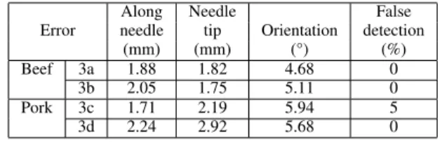
(mm) (mm) (°) (%) Beef 3a 1.88 1.82 4.68 0
3b 2.05 1.75 5.11 0 Pork 3c 1.71 2.19 5.94 5 3d 2.24 2.92 5.68 0
(pork and beef). The low ratio of false detections shows that color-Doppler imaging significantly improves needle detection in beef (0 %) and pork with needle previous trace (5%). These percentages must be compared with those in B-Mode for beef (44%-48%) and for pork with previous trace (26%). The average error along the needle decreases to 2.1 mm and the angular error in needle orientation to 5 °.
For the color-Doppler image represented fig. 3c, the results are slightly superior to those found in the B-Mode image represented in fig. 2c. This is probably due to the uncertainty provided by the color blob thickness surrounding the needle.
IV. DISCUSSIONS
Color-Doppler segmentation is done with a non-specific detection algorithm, able to segment either B-Mode or color-Doppler 2D and 3D images only by adapting thresholding step to the image type (RGB or grey scale). We may still improve the color-Doppler segmentation by applying a threshold/filtering step more specific to color-Doppler data. The error found at the needle tip in color-Doppler is relatively small compared to US volume’s poor quality and resolution (0.4 mm3).
As brightest voxel percentage used in B-Mode segmenta-tions was defined manually, it must be adapted according to US image echogenicity. Furthermore, the iteration number was set intentionally to a low value in order to keep fast detections. Increasing this value may improve the algorithm robustness in B-Mode but will increase computation time.
We chose to compare only straight insertions in order to keep an objective reference given by robot odometry, not by a potentially imprecise manual segmentation on B-Mode images. However, in [13], Adebar found similar errors for straight and curved needle (around 1 or 2 mm) compared to a manual segmentation. These errors are approximately equivalent to the ones presented in this paper. However, they resulted from a slice to slice segmentation assuming that the needle is orthogonal to the slices and thus is sensible to needle orientation with respect to the transducer.
V. CONCLUSIONS
We used needle rotation in color-Doppler ultrasound imag-ing to increase needle visibility thus facilitate its segmenta-tion. Our method does not require any material modifications
of our robotic device and uses needle’s slight asymmetry to induce vibrations in the whole needle. We selected a RANSAC-based algorithm to segment needles in both B-Mode and color-Doppler 3D volumes. We tested our al-gorithm in these two types of imaging and compared the resulting segmentation to a calibrated reference.
The use of color-Doppler imaging results in more robust needle segmentations in case of poor visibility or interac-tion with bright objects in the image like acoustic artifacts or previous needle traces. This property can be useful in brachytherapy, where several objects can appear in the US image.
In the future, the developed color-Doppler segmentation may provide a useful feedback for robot needle steering.
REFERENCES
[1] R. J. Webster, J. Memisevic, and A. M. Okamura, “Design considera-tions for robotic needle steering,” in Robotics and Automation, 2005. ICRA 2005. Proceedings of the 2005 IEEE International Conference on. IEEE, 2005, pp. 3588–3594.
[2] A. Jahya, F. Van der Heijden, and S. Misra, “Observations of three-dimensional needle deflection during insertion into soft tissue,” in Biomedical Robotics and Biomechatronics (BioRob), 2012 4th IEEE RAS EMBS International Conference on, June 2012, pp. 1205–1210. [3] Z. Wei, G. Wan, L. Gardi, G. Mills, D. Downey, and A. Fenster, “Robot-assisted 3d-trus guided prostate brachytherapy: system inte-gration and validation,” Medical physics, vol. 31, no. 3, pp. 539–548, 2004.
[4] G. Fichtinger, T. L. DeWeese, A. Patriciu, A. Tanacs, D. Mazilu, J. H. Anderson, K. Masamune, R. H. Taylor, and D. Stoianovici, “System for robotically assisted prostate biopsy and therapy with intraoperative ct guidance,” Academic Radiology, vol. 9, no. 1, pp. 60–74, 2002. [5] G. S. Fischer, I. Iordachita, C. Csoma, J. Tokuda, S. P. DiMaio, C. M.
Tempany, N. Hata, and G. Fichtinger, “Mri-compatible pneumatic robot for transperineal prostate needle placement,” Mechatronics, IEEE/ASME Transactions on, vol. 13, no. 3, pp. 295–305, 2008. [6] N. Hungr, M. Baumann, J.-A. Long, and J. Troccaz, “A 3-d ultrasound
robotic prostate brachytherapy system with prostate motion tracking,” Robotics, IEEE Transactions on, vol. 28, no. 6, pp. 1382–1397, 2012. [7] M. Baumann, P. Mozer, V. Daanen, and J. Troccaz, “Prostate biopsy tracking with deformation estimation.” Medical Image Analysis, vol. 16, no. 3, pp. 562–576, May 2011, cifre avec soci´et´e Koelis PHRC national prostate-´echo. [Online]. Available: http://hal.archives-ouvertes.fr/hal-00606407
[8] S. H. Okazawa, R. Ebrahimi, J. Chuang, R. N. Rohling, and S. E. Salcudean, “Methods for segmenting curved needles in ultrasound images,” Medical Image Analysis, vol. 10, pp. 330 – 342, 2006. [9] M. Ding, H. N. Cardinal, and A. Fenster, “Automatic needle
segmen-tation in three-dimensional ultrasound images using two orthogonal two-dimensional image projections,” Medical Physics, vol. 30, no. 2, pp. 222–234, 2003.
[10] W. Qiu, M. Yuchi, M. Ding, D. Tessier, and A. Fenster, “Needle segmentation using 3d hough transform in 3d trus guided prostate transperineal therapy,” Medical Physics, vol. 40, no. 4, p. 042902, 2013.
[11] M. Uhercik, J. Kybic, H. Liebgott, and C. Cachard, “Model fitting using ransac for surgical tool localization in 3-d ultrasound images,” Biomedical Engineering, IEEE Transactions on, vol. 57, no. 8, pp. 1907–1916, 2010.
[12] M. P. Fronheiser, S. F. Idriss, P. D. Wolf, and S. W. Smith, “Vibrating interventional device detection using real-time 3-d color doppler,” Ultrasonics, Ferroelectrics and Frequency Control, IEEE Transactions on, vol. 55, no. 6, pp. 1355–1362, 2008.
[13] T. Adebar, A. Fletcher, and A. Okamura, “3-d ultrasound-guided robotic needle steering in biological tissue,” Biomedical Engineering, IEEE Transactions on, vol. 61, no. 12, pp. 2899–2910, Dec 2014.