CLEANROOM DESIGN
by
Douglas H Erickson
Bachelor of Architecture
Bachelor of Science in Architectural Studies Washington State University
Pullman, Washington
1975
SUBMITTED TO THE DEPARTMENT OF ARCHITECTURE
IN PARTIAL FULFILLMENT OF THE REQUIREMENTS FOR THE DEGREE
MASTER OF SCIENCE IN ARCHITECTURE STUDIES at the
MASSACHUSETTS INSTITUTE OF TECHNOLOGY
June, 1987
© Douglas H Erickson 1987
The author hereby grants to M.I.T. permission to reproduce and to distribute publicly copies of this thesis document in whole or in part
Signature of Author Douglas H Erickson Department of Architecture May 8, 1987 Certified by Dr. Leon Glicksman Senior Research Scientist Thesis Advisor
Accepted by
t bJulian Beinart
Chairman MAzSSAOsmTS INSr~iDpartment Committee for Graduate Students
M
ITLib
Document Services Room 14-0551 77 Massachusetts Avenue Cambridge, MA 02139 Ph: 617.253.2800 Email: [email protected] http://Ilibraries.mitedu/docsDISCLAIMER OF QUALITY
Due to the condition of the original material, there are unavoidable flaws in this reproduction, We have made every effort possible to provide you with the best copy available. If you are dissatisfied with this product and find it unusable, please contact Document Services as soon as possible.
Thank you.
Some pages in the original document contain pictures, graphics, or text that is illegible.
CLEANROOM DESIGN
by
Douglas H Erickson
Submitted to the Department of Architecture on May 8, 1987 in partial fulfinent of the requirements for the Degree of
Master of Science in Architecture Studies
ABSTRACT
The development of the integrated circuit which replaced the vacuum tube, started the size reduction process for computer components. These integrated circuits are made from silicon (chips) and are comprised of electronic switches, or gates. The gates are measured in size of microns. The diameter of a human hair is approximately 60 microns across.
Facilities that develop, and manufacture these integrated circuits require the strictest quidelines for environmental controls and prevention of potential health hazzards that personnel may encounter while working in these facilities. The major environmental controls are particle size and number, temperature, relative humidity, air flow velocity, and pressure. Providing this and other forms of control are used to develop what are called cleanrooms. Cleanrooms are used for the manufacture of a number of different kinds of products. The focus of this research will be on the microelectronics industry. This industry leads all other industries in developing systems, standards, and monitoring technologies, to control microcontamination which is the essence of what a cleanroom does.
This thesis will be divided into two parts. The first part defines what a cleanroom is and what it is comprised of. Next, there will be methods presented to design this type of space in a more energy and cost efficient manner.
The second part involves the research in the vertical laminar flow aspect of operating a cleanroom. The vertical laminar flow offers a stru ctured method for controlling air flow and provides an effective means for discharging particulates out of the cleanroom. By comparison, the conventional air flow system throws the particulates in a random fashion. The vertical laminar flow has its limitations. By itself, the vertical flow operates well, but people, and equipment cause turbulence which disrupts its effectiveness. Working with these variables through research, an alternate method of working with this vertical laminar flow was developed. The results, recorded by photographs show an alternative for dealing with the turbulence and eddys caused by the operations in the cleanroom. There will be a discussion followed
by a number of questions, and responses which will be the basis for this research on
vertical laminar flow.
Thesis Supervisor: Dr. Leon Glicksman Title: Senior Research Scientist
ACKNOWLEDGEMENT
The development of this thesis could not have taken place without the input, and knowledge I was able to receive from a number of people.
I would first like to thank Dean John de Monchaux, head of the School of Architecture and Planning at the Massachusetts Institute of Technology for his initial guidance, and granting me financial help from the Cabot Foundation.
My advisor, Dr. Leon Glicksman, who steered me on course, with his experience and
knowledge and gave me the advice I needed. Mr. Tom Yule, A doctorate student in the Mechanical Engineering department with his technical experience and his good nature.
Two firms whom deal with cleanrooms, MC2 with vice president Leo-PierreRoy, and also the architecture-engineering firm of Symmes Maini and MckeeAssociates. Mr. Michael Powers who is a principle there along with Mr. Leo-Pierre Roy from MC2, graciously gave me much literature and their time for my research.
Mr. Tony Collozi from MIT who designed the new cleanrooms at MIT, and who is on staff there gave me good contacts for my research.
My research model which played such a vital role in my vertical air flow research,
would not have been such a success without the input from Mr. Harry Hadley, who was instrumental in the design, and Mr. Anthony Ingemi, who was instrumental in its construction. There firm, B.G. Wickberg and Company, located in North Quincy Massachusetts was kind enough to allow the research model to be built there.
The last part of this acknowledgement is for my wife Leslie, who I give my sincere love and respect, and whom without her support, none of this could have taken place. Hi Mark.
CLEANROOM DESIGN (Energy Efficient Design) Abstract Acknowledgement Table Of Contents PART 1 Chapter 1 1.1 1.2 1.3 Chapter 2 What Is A Cleanroom Introduction Terminology
Factors and Fundamental Design Concepts That Are Important In Cleanroom Design
History
2.1 How Cleanrooms Originated
2.2 Future Trends In Cleanroom Design
Chapter 3
3.1 3.2 3.3
3.4
Management In Cleanroom Operations Introduction
Technical Considerations Attitudinal Factors Clothing
Chapter 4 Energy Efficiency And Cost Savings In Cleanroom Design.
4.1 Introduction
- 4.2 Methods For Energy Efficiency And Cost Savings
2 3 4 6 7 10 31 35 36 37 40 43 46 47
PART II VERTICAL LAMINAR FLOW (RESEARCH)
Chapter 5 Vertical Laminar Flow
5.1 Introduction
5.2 Laminar Flow (Vertical)
5.3 Research Model (Apparatus)
5.31 Design 5.32 Model
5.4 Research
5.41 Research Agenda
5.5 Discussion On Research Process
5.51 Response To Research Questions 5.52 Research photographs
5.6 Related Studies / Future Considerations Chapter 6 Conclusion To Thesis
Appendix: Federal Standard Number 209B
References
5
65 67 69 70 72 74 77 82 93 94 95 1471.1 Introduction
Recent growth in high technology industries, especially electronics, has increased the demand for what are called cleanrooms. Simply stated, a cleanroom is a controlled environment in which temperature, humidity and airborne particulates are all carefully regulated the predetermined standards. Generally speaking, the cleanroom controls three major types of contamination. The first is airborne contaminations. This type of contamination can be of any shape, size, or nature and is transferred by either air convection currents or trajectory off of other particles. In either case, the medium of transfer is air. The second type of contamination is control of particulate matter transferred from one object to another by direct contact. The third type of contamination is the transfer of particulates by means of fluids. This can occur with cleaning solution as well as with lubricants.
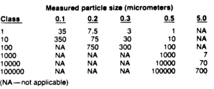
Cleanrooms are classified by the number of particles of certain sizes that are present in a cubic foot of air. A class 1,000 cleanroom has, on average, no more than 1,000 particles of 0.5 microns or larger per cubic foot. And a class 10 cleanroom has just 10 or fewer particles of .10 microns in a cubic foot of air. (see figure 1) In contrast to this, a normal office space will have millions of particles 0.5 microns or larger in a cubic foot of air.
10.000- -10 -DIFFERE\NCE 0 1 0 2 0 5 to0 20 5.0 10 0 PARTcLE SZ (m figure 1
1.2 TERMINOLOGY
In the following report, there will be a number of words referring to cleanroom technology. The meanings to these words will be defined here.
ADSORPTION: Water purification utilizing activated carbon to remove organic contaminants. The porous surfaces of the carbon also trap and retain free chlorine found in municipal water supplies.
CHIP (MICROCHIP) : A square of primarily silicon that is processed to ultimately be an intergrated circuit.
CLASS 100,000: Particle count not to exceed 100,000 particles of a size 0.5
microns and larger per cubic foot.
CLASS 10,000: Particle count not to exceed 10,000 particles of a size 0.5 microns
and larger per cubic foot.
CLASS 100 : Particle count not to exceed 100 particles of a size 0.5 microns and
larger per cubic foot.
CLEAN ROOM: A cleanroom is an enclosed area employing control over the
particulate matter in air with temperature, humidity, air flow patterns, air motion, pressure control and lighting as required. Cleanrooms must not exceed the particulate count specified in the air cleanliness class.
CONVENTIONAL FLOW (Nonlaminar Flow) Clean Room: A clean room with no
requirements for uniform air flow patterns and air velocity
DEIONIZATION : (demineralization) Method of water purification which is
accomplished by passing water through synthetic resins which exchange H+ (cation) and OH- (anion) ions for ionized impurities in water.
DESIGN CONDITIONS: The environmental conditions for which the clean space is designed.
DIE: A seperate chip on a wafer.
DISTILLATION: Water purification by phases. Water is first evaporated, leaving impurities behind, and then condensed in a water cooled heat exchanger (condenser).
DOP: (Dioctyl Phthalate) Smoke test that determines the amount of smoke penetration through a filter.
EDDY: Air running contrary to to the main current.
GATES: A circuit that has an electrical output dependent on its input. Smallest
subclass of current on a chip.
HIGH EFFICIENCY PARTICULATE AIR FILTER (HEPA): A filter with an efficiency in excess of 99.97% for 0.3 micron particles as determined by what is called a Dioctyle Phithalate (DOP) test.
HIGH EFFICIENCY PARTICULATE AIR FILTER (VLSI): A filter with an
efficiency in excess of 99.9995% for 0.12 micron particles.
INTERGRATED CIRCUIT (IC) : An electronic device that performs the functions of many thousands of transistors.
LAMINAR FLOW: Air flow in which the entire body of air within a confined area moves within a uniform vertical air pattern along parrallel flow lines.
LAMINAR FLOW ROOM: A cleanroom with a laminar flow requirement.
LARGE SCALE INTEGRATION: Microelectronics manufacturing technology for intergrated circuits with line geometrics of 2-micron widths..
MEMBRANE FILTRATION: Water purification sometimes called "absolute filtration", this method employs a non-contaminating screen of carefully controlled pore size to trap non-dissolved impurities on the surface of the membrane. These filters, typically with a pore size of 0.2 or 0.45 micron, are used to remove particles and bacteria from water
MICRON: A unit of measurement equal to one-millionth of a meter (0.000039"). Twenty-five microns equal 0.001".
NON-LAMINAR FLOW ROOM: A clean room that does not require a laminar flow pattern.
PARTICLE SIZE: The maximum linear dimension of the diameter of a particle usually measured in microns.
PREFILTERS: A filter to trap gross particulates located upstream from and with lower collection efficiency than the HEPA filter.
TURBULENT FLOW: A Fluid flow in which the velocity at a given point varies
UNIFORM AIRFLOW: Unidirectional airflow pattern in which the point-to point
readings are within plus or minus 20 % of the average air flow velocity for the total area of the laminar flow work zone.
VERY LARGE SCALE INTERGRATION (VLSI) : Microelectronics manufacturing technology for intergrated circuits with line geometrics as small as 0.1-micron widths. WAFER: A thin, flat circular disk of primarily silicon that is masked, oxidecoated, doped and processed for separation into numerous electronic devices or for packaging as an intergrated circuit.
1.3 FACTORS AND FUNDAMENTAL DESIGN CONCEPTS THAT ARE IMPORTANT IN CLEANROOM DESIGN
Precision manufacturing of microelectronics devices is possible only when it is carried out in cleanrooms where there are extremely clean environments. For integrated circuits The fabrication process begins with the slicing of thin wafers from single-crystal silicon boules 100 mllimeters or greater in diameter. Th wafers are cleaned, and various semiconductor materials are deposited in discrete patterns in a series of layers. The patterns are repetitively deposited to form circuitry contained within a die that is a few millimeters on each side and has component widths and spacings that are a few microns wide. The pattern preparation method is based on the depositing of a layer of semiconductor material, followed by lithographic imaging on a layer of photosensitve material. This material is selectively removed, leaving the desired pattern exposed for further processing through one of several methods. Processing methods include liquid phase or dry gas etching, sputtering, vapor phase deposition, etc.
Following the pattern development steps, the wafer is cut into discrete chips. Each chip is then mounted on a suitable holder, and electrical connections are made for subsequent use.
At any step, the wafer or chip may be exposed to the ambient environment, and particulate contaminants can be either ingested or deposited on critical surfaces. The prevention of these contaminants is curtailed by good fundamental design factors in cleanroom design. There are many factors that play an important part in the design and total expense of a cleanroom installation. Along with these factors is the recent concern about the health risks involved with personnel in the cleanroom environment.
In the initial planning stage, two basic considerations should be answered first:
1. What will be the purpose of the room? 2. What degree of cleanliness will be
required? After this has been established, emphasis should next be placed on the allocation of space; position and type of equipment to be installed within the room; the number and placement of personnel and their internal traffic pattern.
Also, the compatibilty of processes, the equipment operating processes and maintenance techniques to economically achieve the project manufacturing requirements should be established.
After these factors have been layed out and the design is set, the fundamental criteria for good design and control should be considered.
These fundamental issues are:
1. Airborne Particle Control
2. Particulate Control
3. Air Pattern Control
4. Pressurization
5.
Lighting
6. Temperature Control
7. Humidity Control
8.
Cleanliness
9. Control
10. Vibration / Acoustics
11
Room Construction Specifications and Operations
1. Airborne Particles
Airborne particulate matter can be organic or inorganic. Most contamination control problems concern the overall contamination within the air, but applications exist for specific contamination control of bacteria, spores, and viruses that are contained in the air.
Airborne particles range in size from 0.01 microns to several hundred microns. Conditions for clean space vary widely with industrial and research requirements.
A reference on the control of airborne particulates is the Federal Standard No. 209B.
(see appendix)
2.
Particulate Control
Before any methods of contamination control of airborne particles can be used successfully, a decision must be made as to how critical this particulate matter is to the process or operation in question. The allowable size of an airborne particle at a point within an area depends on the most critical dimensions and tolerances of the process to be performed at that particular point.
At the same time, consideration must be given to the quanity of the particles of a given size that might be present at a particular point with the area.
It has been proven in studies that there is a definite relationship between the size of a particle and the time in which it may be airborne, ( 1. Austin, 1970.) so it is beneficial to discuss airborne particles by quanity of a given size. Federal Standard2O9B discusses this relationship see appendix to further analyze the level of contamination to be considered.
This can be divided into external sources and internal sources.
External Sources: For any given space, there exists the external influence of gross atmospheric contamination of air pollution which tends to find its way into all areas of a working environment.
The external contamination is brought in primarily through the air-conditioning system which supplies the working space with outdoor ventilation makeup air. In addition to the air-conditioning system, external contamination can infiltrate through doors, windows, and cracks in the structure. The contamination generated to the process is controlled primarily by the type of filtration used.
Internal Sources: The greatest source of internal contamination is the personnel
themselves. All people continually shed particles (organic and inorganic);
The amount can vary from as few as several hundred particles per hour to several thousand particles per hour, depending on the indivivual.
Skin is constantly flaking off and generating particles in the 1 micron range, and exaled breath contains large quantities of particles ranging in size from sub-microns to
several hundred microns. (2. Cambridge Filters, 1986.)
In addition to people, and processing, every activity involving friction of surfaces creates some type of contamination. Besides the contaminants from processing, " the
simple act of writing with a pencil on a piece of paper generates an aerosol cloud of many thosands of very fine carbon particles and paper fibers. Even the movement of two pieces of metal together generates a certain amount of particulate matter which can be forced to be an airborne contaminant." (3. Cambridge Filters,1986.)
Within any working environment, a certain dynamic situation exists in the air. Movement results from people working, activity of service equipment within the processing area, fans blowing, motors rotating, etc.
All of these motions impart kinetic energy to the air and cause it to move at random
velocities within the space.
An example of this would be a person walking down an aisle or hallway, imparting kinetic energy into the air causing air motion as the gas molecules in front of him are put into motion.
Fine particles are caught up in a random current within a room and are easily moved from one location in the room, to another. This transfer of contamination through random air currents from one part of the room to another is known as cross-contamination and is a significant contribution to the contamination level at the worksite. A resulting contamination buildup occurs within a space and reaches a plateau or steady state condition. A plateau count of 0.5 microns and larger would range anywhere from several thousand to several million particles in a typical manufacturing environment. During off hours or lunch breaks a noticeable reduction in the contamination level will occur,in the location of processing equipment.
(4. Cambridge Filters, 1986.)
Once the required cleanliness level is established for a facility or room the location of each process to be performed within this area should be decided. This location of each process should include the position of each operator in the facility. While preparing this layout, consideration should be required for the area for each process, each operator, and necessary service equipment.
The position of the operative relative to the process, and the location of each process relative to another will indicate the need for laminar flow.
Other factors, in conjunction with the size and quanity of airborne particles, can also influence the degree and method of contamination control. Some typical considerations are:
1. How the product is affected by particles?
2. Will toxic, explosive, or other harmful fumes be present in the process?
3. Will oders be generated?
4. What type of airborne contamination will the process be affectrd by?
The answers to these questions could determine:
A. If the primary air may be recirculated.
B.If it must be exhausted, and in what quanity.
C. How the supply or exhaust air must be treated or conditioned.
Isolation is one of the most important considerations in applying contamination control. Isolation may be divided into direct, reverse, and mutual isolation.
Direct isolation occurs when the product is to be protected from contamination generated by an external source, service equipment, or personnel. This tends to be the simplest type of contamination control, because consideration of the required cleanliness level can be limited to the product only, the air content need not be considered once it has passed over the product.
Reverse isolation is used when the product generates contamination; the service equipment or personnel, or both must be protected from this contamination. In most cases, -the air requires special care after it has been exhausted from the area, and before it is reintroduced to ambient conditions.
Mutual isolation is recommended when the product is to be protected as in direct
isolation but the contamination generated by the product needs control. Mutual
isolation is also necessary when two adjacent products or processes must be protected from contaminating each other. This type of isolation is not only the most difficult to control but the most required. Mutual isolation normally requires the use of laminar control.
3. Air Pattern Control
Air should be directed to obtain the cleanest air at the most critcal work areas. As contaminants are entrained, they are easier to be removed from the room. Two options are available:
1. The introduction of large quanities of air at low velocities in the area of the most
critical work areas.
2. An unidirectional movement, usually downward or across the room, prior to removal from the space. The choice of specific air arrangement should be based on the criticality, of the conditions to be maintained in the space, size, and the ratio of space occupied by the nature of these operations to be performed in the room.
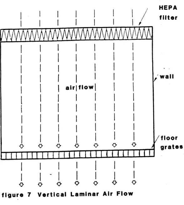
Laminar Flow: In a laminar flow system, air is introduced evenly from one entire
surface of the room, such as the ceiling or a wall, with flow at constant velocity across the room and removal through the entire area of an opposite surface. Laminar flow provides a direct, predictable path which a micron size particle will follow through the clean room, with the minimum opportunity for contaminating any room component.
It also provides a mechanism for directly removing the particles constantly generated within the room introduced into the air stream. Ideally, the flow sreamlined would be uninterrupted and, although personnel and equipment in the air stream do distort the streamlines, a state of constant velocity and static pressure is approximated. Most particles that encounter obstructions in a laminar air flow like personnel and equipment, will strike and continue around it as the laminar air stream re-establishes itself downward. There are, among other conditions two possible conditions that may arise from laminar flow striking obstructions. These are called eddys, and the area of virtually zero velocity at surfaces parallel to the air stream (This action will be further discussed in Part II) to provide good air movement to prevent settling of particles, air flow velocities of approximately 100 f.p.m. are recommended as standard design of laminar flow cleanroom systems.
These average air velocities can be used in laminar flow rooms because of local high velocity are minimized. Although it has been stated by sources that air velocities below 70 f.p.m., will cause prevention of particles to settle. Normal body movement has little effect above 70 f.p.m., while air velocities above 110-120 f.p.m. contribute little contamination control advantage. (5. Cambridge Filter, 1986.)
Laminar flow rooms can usually be operated without the need for air locks, air showers, and restrictions on occupant movement. These rooms fall into three categories; vertical flow, horizontal flow, and diagonal flow with diagonal flow used very seldom except on certain kinds of equipment processings.
Vertical flow consists of an entire ceiling of HEPA filters. Ideally, a grated floor
serves the air exhaust. As it moves through the ceiling, it is filtered essentially free of all particles 0.3 microns and larger. This type of air flow provides a uniform shower of air which bathes the entire room in a downward flow of clean air. Contamination generated in the space will not move laterally against the downward flow of air and will not contribute to a contamination level buidup in the room. This type of design provides the cleanest working environment that is presently available.
Horizontal flow uses the same filtration air flow technique as the vertical flow system, except that the air flows from one wall of the room to the opposite walls. The supply wall consists entirely of HEPA filters supplying air at approximately 100 f.p.m. across the entire section of the room. This air then exits through the return wall, or ceiling return, at the opposite end of the room and is recirculated within the system. This type of flow has the same degree of filtration and the same air flow characteristics as the vertical air flow sytem.
As with the vertical air flow, this design removes contamination generated in the space at a rate equal to the air velocity and does not allow cross contamination from one side of the room to another perpendicular to the air flow. However, a major limitation to this design is that vertical contamination in the direction of the air flow will occur.
In this design, the first air, or air first coming out of the filter wall, is as clean as air in the vertical flow room. The process activities can be oriented mostly to have the cleanest, most crical operations in the first air, or at the clean end of the room, with progressively less crical operations located toward the return air, or dirty end of the room.
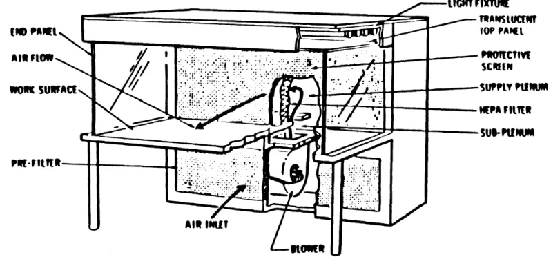
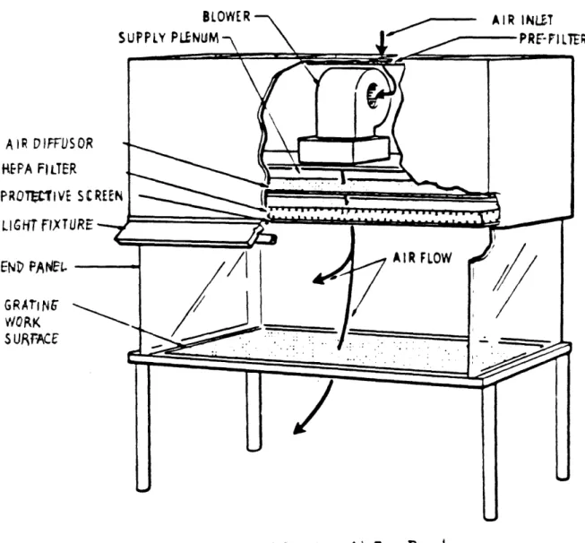
Point of use: All laminar flow arrangements are applicable to point of use stations
as well as entire rooms. In combination with conventional flow systems, they can provide small areas with very high degrees of contamination control. Where critical control is required, the laminar work station is often the only acceptable means for meeting the operational criteria.
Conventional Flow: An arrangement for conventional flow air distriution. Air is
supplied through large ceiling outlets, flows generally downward, and is removed near the floor level. Air velocities across the room should be approximately 50 f.p.m. Lower floor velocities may permit particles to settle, while with conventional distribution, higher velocities may generate objectional local turbulance and drafts. Although the contamination level is greatly reduced. This method does not offer the same protection as laminar flow. (See Figure 2.)
4. Pressurization
Pressurization in a cleanroom facility is required to provide a purposeful migration of air from the most clean space to areas of progressively less cleanliness. The design should be based on a nominal 0.05 in pressure diffrerential between clean and less clean zones. Pressures greater than this will result in greater make-up air and can begin creating problems with personnel doors.
There are two primary considerations to recognize when designing for pressurization.
1. Differential pressure between functional spaces.
2. Building differential pressure.
Pressure between functional spaces will be influenced by both recirculation air quantity and make-up airflow, while building pressurization is ultimately affected only by make-up air flow quanity. To provide control over room pressures, air flow variations
should be minimized.
5. Lighting
In cleanrooms, lighting must be supplied as part of the design system, because of design and application of uniform contamination control equipment. The normal lighting level is established at 100 footcandles at 30-42 inches from finished floor, (table-top height) to provide a reasonable level to adequately see the process without eye fatique.
6. Temperature Control
In many cleanroom applications, particularly semi- conductor facilities, the ability to hold temperature constant is more important than the absolute value. As the precision of the process increases, the need for accurate temperature control increases. Control of plus or minus one degree fahrenheit is common for such processes as x-ray, and laser lithography.
In cleanrooms of cleanliness class 1000 or better where full protective clothing (bunny suit) is required, temperatures of 68-72 degrees fahrenheit (20-22, centigrade) are necessary to satisfy human comfort. Generally, these temperatures will also satisfy process requirements. For less stringent functions such as assembly or packaging, where cleanliness classifications of 100,000 are common and protective clothing is less restrictive.Temperatures of 70 -74 degrees fahreheit ; ( 21-23, centigrade) is
adequate.
7. Humidity Control
Humidity control for cleanrooms can be extremely important in many processes. Humidity control of 40% R.H. to 45% R.H. is desired with tolerance of 2-5 degrees plus or minus will satisfy most conditions. Generally, the specific process will dictate the humidity requirements. For energy considerations, it should be specified with as wide a tolerance as possible.
Humidity control is necessary to, among other things:
1. prevent corrosion
2. prevent condensation on work surfaces.
3. eliminate static electricity.
4. provide personnel comfort.
Corrosion of precisely manufactured surfaces including bearings electrical contact surfaces, ball-bearing raceways, and miniature-gear trains occurs with above 50% R.H. At relative humidities much below 40%, static changes may form, attracting dust particles which later may become airborne in massive concentrations.
8. Cleanliness
The primary purpose of a cleanroom is to provide an environment in which particulates are contained within some specified unit. Federal Standard 209B, provides the criteria for defining clean -rooms. This standard is primarily a definition and does not prescribe methods for achieving cleanliness levels. The current definition of classes
100, 1000, and 100,000 refers to the maximum number of particles 0.05 microns or
greater per cubic foot of cleanroom volume. (Federal Standard 209B, see appendix)
The primary sources of particle contamination besides personnel which is primarily a management issue is:
I. I-nfiltation
H. Internal generation
III. Introduction of make-up air
I. Infiltration: High Efficiency Particulate Air (HEPA) filters are used in both
vertical and horizontal types of design in the control of infiltration into the cleanroom. Air flows into the work area, and exits in either one of two ways; through perforated floor sections into an air plenum; or through air grills at the floor level or side walls.
For the filtering of suspension matter," three effects are performed:
1. screening effect: not only particles bigger than the distance between fibres are
retained, but also particles whose streamline passes so near to a fibre that they collide. 2. inertia effect: Particles above 1 micron, where they are thrown out of their streamline when it deviates sharply to pass a fibre of the filter median.
3. diffuse effect: Particles below 1 micron, where constant collision with the
molecules of the surrounding gas lead to an erratic path (Brownian movement.)"
(6. Schicht, 1985. )
Due to the low penetration velocity of the air through the filter paper, pleating is necessary in order to arrive at compact filter units.
There are two philosophies as to pleating.
1. American: Pleats of 15-30 cm. in depth, with distance holders of
corrugated aluminum sheet metal in between paper pleats.
2. European: Employs low depth pleats of narrow spacing,with
distance holding by threads. (7. Schicht,1985.)
An important item to emphasis is the location of the HEPA filters. "The HEPA filters should always be located so that they are the last items of the mechanical equipment. This insures that all the air entering the cleanroom is filtered and that there is no possibility of contamination with unfiltered air." ( 8. Kilpatrick, 1984.) Careful installation of the HEPA filters is important as to not cause leakage around the edges. The ratings of a filter is based on the resistance to air flow, its aerosol removal capabilities, and its dust holding capabilities.
By definition, the HEPA filter must demonstrate a minimum collective efficiency of
99.97% for 0.3 microns (DOP) test, and a maximum filter pressure drop of 1.0" w.g.
"The 0.3" micron challenge aersol was selected since both theory (OSPD) reports 3460) and experiments indicate that a particle of this size is the most difficult type to capture by a fibrous filter." (9. Kilpatrick, 1984.) This form of resistance has strongly emerged within the last ten years.
Particulate filtration is predominately done by two generic classes of fibrous filters.
1. viscous impingement. 2. dry type.
Impingement type filters are constructed of coarse fibers arranged in a porous bed. Dry types differ from impingement types in that they have smaller sized fibers of
more densely spaced media. In both types, the pressure drop across the filter increases with dust loading to a point where they should be replaced. This is normally done when the air resistance reaches 2" w.g.
II. Internal generation:
A. Equipment and materials in clean area B. Maintenance
C. Process Equipment.
III. Introduction of make-up air.
9. Controls
Controls are critical to the overall system design and required performance. However, two things should be kept in mind:
1. A system, no matter how well designed, will operate no better than its controls.
2. Controls cannot correct what is fundamentally a design problem.
A selection and design of the controls is an integral part of the entire design process.
Precision instruments should be specified where precision is important. This precision is usually limited to:
1. make-up air system for humidity control.
2. recirculation system temperature control.
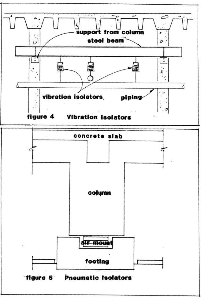
10 Noise And Vibration
Noise is one of the most difficult variables to control within contamination control equipment, due to the high volumes of air necessary to provide the cleanliness levels required. For normal applications of laminar flow equipment, the noise level is designed to be below 65 decibels. Air-handling systems, fume hoods, exhaust systems and equipment areas (chillers, boilers, pumps, etc.) must be carefully located and appropriate silencers and sound absorbing elements must be used to attain a sound level that is acceptable to the personnel. Levels of vibration are controlled by utilizing
structural designs with stiffness and mass.
Pedestrian traffic within the cleanroom is one of the most important vibration sources. The most reliable solution other than administrative controls are the structural seperation of high traffic areas, or the use of heavier structural components to bring footfall- induced vibrations within accepted limits.
11. Room Construction And Operations
Construction Finishes:
1. General Smooth, monolithic, cleanable, abrasive, and chipping resistant, with a minimum number of seams,joints, and no crevices or mouldings.
2. Floors: Sheet vinyl, epoxy, or polyester coating cove wall base.
3. Walls: Plastic, epoxy, baked enamel, or polyester with minimum projections.
4. Ceilings:
5 Lights:
Plaster covered with plastic, epoxy, or polyester coating plastic-finished acoustical tiles.
or with
Flush mounted, sealed with tube removal preferrably from outside of room.
Personnel And Garments:
1. Hands and face are cleaned before entering area.
2. Lotions and soap containing lanolin are used to tighten skin particles.
3. Solvent contact with the skin is conducive to skin peeling and avoided.
4. Wearing cosmetics and skin medications are not permitted.
flaking and is
5. Smoking and eating are not permitted.
6. Lint-free smocks, coveralls, and head and shoe covers are worn.
Materials And Equipment:
1. Equipment and materials are cleaned before entry.
2. Nonshedding paper and ballpoint pens are used. pencils and erasers are not permitted.
3. Work parts are handled with gloved hands, finger cots, tweezers, and other methods to avoid transfer of skin oils and particles.
Particulate Producing operations:
1. Grinding, welding, and soldering operations are shielded and exhausted.
2. Containers are used for transfer and storage of materials.
Entries:
Chapter 2 History
2.1 How Cleanrooms Originated
The orgins of cleanrooms today are a result of advancing technology in the field of mechanical science. This advancement is a twentieth-century discovery. Cleanrooms produce many present day products of sophisticated design. Control of the factors in and about a product is a function of tecnological advancement in science. This is true for many sciences. The first of these sciences to recognize this need was medicine. Medical science controlled the environment in what are called "operating rooms". The nature of work performed in an operating room on humans is similar in nature to work performed in cleanrooms on equipment. Room decontamination functions are both necessary and vital to continued, successful cleanroom operation. The events leading to the development of operating rooms were initially paralleled by events leading up to the development of cleanrooms. With greater emphasis being placed on miniaturization of products by the electronic age, however cleanliness requirements for some cleanrooms exceed those for operating rooms. Techniques of workers in operating rooms and cleanrooms are similar in that they are controlled.
Various objects, tools, and areas are considered to be either contaminated or uncontaminated. The worker's actions are goverened by these considerations.
The major difference between operating rooms and cleanrooms is that in operating rooms sterility of objects is of major importance. In cleanrooms, the quanity of particulate matter is of major concern. Particulate matter is of little impotance in an operating room as long as it is sterile. Cleanrooms have experienced little difficulty with bacterial growth on items. This can be attributed to several reasons:
1.Lack of bacteriological food. 2. Lack of bacterial colonies. 3. Low humidity.
Louis Pasteur (1822-1895), recognized in the late 1800's that micro-organisms caused disease. His recourse was to kill these organisms by the use of chemical sterilants. It was this twentieth century discovery that particles too small to be seen could also have a major effect on precision manufacturing product yields.
Cleanrooms or rooms that were the predecessors of modern day clean -room can trace their beginning back to World War I days. At that time there was no "cleanrooms" as we know of today. But there were controlled areas that performed similar functions.
These controlled areas within factories and laboratories attempted to eliminate the gross contamination associated with manufacturing areas. This contamination, consisting of heavy dust- laden air, had caused seizure of small bearings and gears used in the first aircraft instruments. As a result, controlled assembly areas were built.
By segrating the work areas from other manufacturing operations, and by providing a
filtered air supply, contamination control was first effected by cleaning practices. With the beginning of the World War II period, better filtration systems were developed: air conditioning and room pressurization were considered essential. Personnel protective clothing were added later, as were air showers and personnel cleaning equipment. In this period there were attempts to improve the quality and reliabilty of such areas as metrology; precision optics such as bombsights, gyroscopes, and timing devices, met limitations which appeared to relate to surface cleanliness. ( 10. Austin, 1970.)
Further study revealed that surface cleanliness was a function of how clean the environment could be made and controlled. Up to this point there was little known
write their own independent and operating specifications and standards for cleanrooms.
Many theories were generated and practices were based upon incomplete data. Because of this the field of contamination control lost a lot of credibilty in the 1950's.
The first document accepted as a workable document for cleanrooms was one done by the United states Air Force entitled "Standard Functional Criteria For The Design and Operation Of Clean Rooms". (Air Force Technical Order 00-25-203) It was prepared because of the confusion to the various contamination, temperature, humidity, and pressure requirements for cleanrooms. The Technical Order 00-25-203 was published in 1961. Also, in 1961 the Sandia Laboratories located in Albuquerque, New Mexico started work on a new type of cleanroom design. This facility is a part of the United States Atomic Energy Commission. Sandia has a vital interest in the field of contamination control. Absolute cleanliness of contact points, freedom from corrosion, no shorts from metallic particles were vital for the complexity of the systems at Sandia. (11. King,1986.)
What resulted from such strict specifications was a design team from Sandia who developed what is called "laminar flow" cleanroom design. (1962) This design concept developed many of the designs currently in use; and then developed what is now called "Federal Standard 209B".
During the time of the development of Federal Standard 209B this team had the assistance, among others, all military and government agencies, and NASA. This Federal Standard 209b was first published in December of 1963.
From its inception in 1962, laminar flow technology has been applied to the design and modification of new and existing cleanrooms. Laminar flow systems have taken the form of both rooms and individual work stations.
The years from 1962 to 1965 saw the laminar flow design used for mostly aerospace industry. From the mid to late 1960's the laminar flow design was starting to be used in the pharmaceutical industries, and the application in hospital operating rooms.
In addition to this new laminar design, other advances also occured at this time to make the over all design of the cleanroom more efficient. Among some of these advances were:
1. Increased efficiency in the sealing of HEPA filters (HEPA Filters were first marketed in 1950.) 2. Instrumentation for particle counting.
3. Filtration of process gases, and liquid starting with treated water that is used in the microelectronic manufacturing industry.
The microelectronic manufacturing industry is the largest user for cleanrooms these days. Other fields include:
1. Medical 2. Pharmaceutical 3. Military 4. Aerospace 5. Food processing 6. Optics 7. Nuclear 8. Precision Manufacturing 9. Research facilities
2.2 Future Trends In Cleanroom Design
Revisions of the Federal Standard 209B are currently being proposed to control particles 0.1 microns in diameter and larger to less than 10 particles per cubic foot (Class 10). Also, for particles 0.1 microns in diameter and larger to less than 1 particle per cubic foot (Class 1). Because of this advancement, laser (light) scattering particle counters are now being used for the counting of these particles.
(12. King, 1986.)
Class 100 is now being tested for lesser needs with class 10, and classl being specified for the current, high quality production.
Along with these higher standards, the fundamental criteria mentioned in chapter 1 are becoming more precise. New areas of concern are evolving. One of these areas to be looked at is the eletrostatic changes, and electromagnetic interference which is more of a problem with the micro-computer.
With class 10 and class 1, cleanrooms now being used, there will need to be a revision in the Federal Standard 209B to accomodate the proposed revisions.
Chapter 3 MANAGEMENT IN CLEANROOM
OPERATION
3.1 Introduction
Proper management of personnel in the operation of a cleanroom is important because personnel are the largest contamination source. "It is recognized that the human can contribute up to 80% of particulate contamination in a clean envoronment with air filtration making a 5% contribution and the work piece and equipment making up the remainder at 15%." ( 13. Waring, 1984.) The main reason for this is the normal process of the skin regeneration on the body. The body is continually loosing skin flakes all the time. "The body will possibilibly shed up to 250,000 scales per minute in the static state." ( 14. Waring, 1984.)
It is important to recognize, that the successful achievement of contamination control depends as much on attitudinal factors as on the technical considerations. This chapter will deal with these considerations by analyzing three parts.
1. Technical consideration.
2. Attitudinal factors.
3.2 Technical Considerations
The management starts with the proper layout of the facility, specifically the management of the circulation. Present cleanroom technology uses either full laminar flow or clean tunnel-bay systems. In the full laminar flow design, the entire facility is divided into clean modules, each module combines HEPA filtered ceilings wih grated floors. This concept is for full flexibility in the equipment size and layout. An exception to this would be the wall location for the return air. But you pay for this flexibility, the tunnel approach handles traffic flow in a highly efficient manner. The main artery, or tunnel, connecting the modules is the location of the densest traffic flow. This system does not have the open space for flexibilty, but by not using the entire space there is a cost savings. (see chapter 4, section 3, "Flexibility")
In either case, the overall cleanroom plan must manage the movement of personnel. At the point of entry into a intergrated circuit manufacturing facility the person should immediatly start mentally and physically work to create a clean atmosphere. Street shoes should immediately be removed and or be covered by special slippers. As one proceeds through the facility, further levels of cleanliness should immediately become evident.
Floors, even in the reception type areas should be exceptionally clean. The level of cleanliness should actually increase as one approaches the actual fabrication area. These environments should take on a hospital-like appearance. Even locations relatively far from the fabrication area, like the floors and walls should be finished with a cleanroom type appearance as stated in chapter one. (1.3, section 11)
Besides always being constantly cleaned, the main circulation floors should be covered with what is called a dust collecting rug or mat. The cleaning of these areas should be done with the use of lint free brooms, and vacuum cleaners with a good filtering
The manner in which personnel enter and exit the fabrication areas should provide a further measure of cleanliness. Essentially, all the people who enter into the fabrication area should pass through several staging areas.
There will be four stages used in this example. These areas are the different levels that should be achieved to meet a level of utmost cleanliness. The first area should be a location where employees and visitors would remove their jackets along with the slippers that were issued upon arrival to the facility.
The next stage would develop through a pass through air -locked set of doors into a second area where cleanroom clothes are put on (slippers would remain on.) A third area would be a relatively large laminar flow area, equipped with a metal grating floor and HEPA filter ceiling. In this area, personnel would put on their second pair of slippers and wash their hands. These areas could be equipped with what are called electronic eyes which would allow the people to wash and dry their hands without touching any surface. . A fourth and final stage would consist of a air wash tunnel. This will last approximately 30 seconds. A general consensous about air showers is that their function is more for pyschological reasons than actual performance.
At this point people would enter the fabrication area. What is important here was the thought process people would go through to mentally concentrate on reducing the contamination spread.
The next point to manage would be the traffic movement. Movement of workers within the cleanroom create air currents that interfere with proper laminar flow. Cleanrooms that are short of a perfect laminar flow are going to have pockets of less clean air and locations of settled particulates.
Unnecessary movement in the cleanroom will stir up these problem areas and could allow contamination to be placed upon the product being manufactured. Traffic should be limited as much as possible for peak performance.
Visqueen or plexiglass shields can help in isolating critical areas from air movement caused by the movement of personnel through critical area. Intercoms, and also pass-throughs are helpful in maintaining low traffic levels. Any pass-through should be accompanied by a intercom system to prevent the use of the pass- through for purposes of conversation.
Another item to manage is the proper handling of the clean room product. Operators in the cleanroom must realize the importance of protecting the product at all times from contamination, and must know how to do this. Cleanroom guidelines must be established and followed. Current personnel should be retrained; incoming personnel and visitors should not be admitted until they have a clear understanding of these guidelines. Everyone connected with the cleanroom facility should know and follow the guidelines.
A final note on some specific issues that should be implemented in the management of
cleanroom operation:
1. Ordinary paper should not be used in a clean room of less than class 10,000
rating.
2. No food, gum, candy, or smoking material should be allowed in the cleanroom.
3. The use of cosmetics, rubber bands, and plastic gloves should be prohibited in the cleanroom.
4. If a vacuum cleaner is to be used in maintenance, make sure it is properl
filtered.
5. Materials entering the cleanroom should be either double bagged or wiped
down with diluted alcohol.
6. Avoid turning laminar flow hoods off, even during brief shutdowns (absence of movement will allow contamination to settle.)
7. Do not allow employees to sit on work surfaces or stand on any furniture.
8. Segregate coats and sweaters from cleanroom garments.
9. Leave all personnel items outside the cleanroom area.
10. Vent all locker storage with laminar flow.
3.3 Attitudinal Factors
Product effectiveness in the cleanroom ultimately depends on the users. In many cleanrooms the personnel fall into three categories: production (operators), personnel dedicated to mainteanc,technicians and engineers. The hierarchy is engineers followed
by technicians, and than operators. Also in many cleanrooms this is the same as the
technical hierarchy.
In the environment of a cleanroom facility with everyone wearing white, and working in such a sterile atmosphere there is a sense of anonymity resulting in this necessity of wearing cleanroom garments. In many cleanroom facilities there is a assembly line atmosphere which after a while creates a task identity and significance problem.
This sameness of environment and task can result in an attitude problem. This is even compromised by training programs of personnel that is primarily prescriptive (do this; don't do that) instead of educating operators. A final point in this area, is that
"Cleanrooms, perhaps more than any other manufacturing setting ever, provide little opportunity for operators to guage the quality or progress of their work. Both the product and the problems that affect it are well below the visual threshold. Operators are left to follow procedures designed to ensure proper manufacturing processing, but this situation means that the work is more ritualized than it is product-focused. In effect, operators are working in an infomational void." (15. Northcraft, 1986.) This sense of anonymity also can develop into a sense of frustration, or a non-commitment to work attitude in this working environment.
In conclusion, to promote a positive attitude in the cleanroom environment to increase the performance of personnel, a number of steps should be taken. Among those:
1. Thorough and proper training. The personnel should be knowledgeable in the
whole design process. Not in just their task, but also what everyone else does. A good way would be to rotate people to eventually have them work on all the different tasks. This will make personnel understand the whole picture, and better understand what each position is contributing.
That goes for operators, technicians, and to a point engineers knowing each others
job. This will in affect develop a repect for each others task as well.
2. Develop ways of communicating with each other. One way is by the use of an inter-coin system. Another is to develop predictable work schedules for personnel so that everyone knows each others schedule. This would help in not disrupting
workers.
3. Room finishes: Cleanrooms have the same problem that is apparent in operating
rooms and similar rooms in hospitals. What hospitals are doing now, and what cleanroom facilities should do now is to create more of an exciting space visually.
This is done in hospitals now by the use of color, and wall murals. Another area that needs to be looked in cleanrooms is the floors. For vertical laminar flow, the use of floor grating is effective for laminar flow. But walking on this grating all day can be very uncomfortable on the feet. What some Japanese facility designers have done was benefiscial. "Japanese facility designers recognized that walking on grating all day long would most likely become fatiguing. Thus, they replaced gratings with solid flooring on major traffic paths in sections of the fabrication area where ultimate cleanliness was not mandated.
It soon became evident however, that flooring made up entirely of steel grating would have psychological as well as functional drawbacks. One Japanese manufacturer solved this problem by placing prefilters directly under gratings."
(16. Edmark, 1984.)
As cleanrooms become more sophiscated the products will become smaller, and the equipment will be doing more of the work load. This will make the personnel even more alienated. And unless the personnel can develop an attitude of say, a craftsman, or someone that feels he or she is really contributing by being managed as such, maximum productivety will not be achieved.
3.4 Clothing
As mentioned in section 3.1, personnel in the cleanroom are the biggest potential contamination contributor in the clean room. Because of this factor the managing of the proper attire is mandatory in a cleanroom. "Full smocks (i.e., bunny suits and jump suits) are standard issue in all fabrication areas, and considerable attention is devoted to the tailoring of these smocks." (17. Edmark,1984.) Clean room clothing is not a requirement to protect the personnel. It's only function is to protect the environment of the work piece.
Personnel shed large amounts of skin flakes all the time. " The skin and hair
constantly shed tiny flakes, composed mostly of the protein keratin surrounded by what is left of the membrane of the dead cell. Moisture droplets are ejected with every exhalation, blink of the eye, sneeze, cough, and even every word spoken. The clothes we wear also shed tiny particles. " (18. Waring, 1984.)
"To make matters worse, people use such products as body powders, cosmetics, powdery deodorant sprays, and hair sprays, all of which eventually ends up as air borne contamination. These products contain an amazing variety of compounds and metals, including iron zinc, and titanium compounds, mica dust, carbon black, and numerous organics. Even the best cleanroom garment available is not capable of containing all of the human generated contamination." (19. Northgate, 1986.)
The cleanroom clothing must be made of a fabric and designed into a series of garments which in combination will restrict the passage of particulates either through the garment itself or by -passing closures. Cleanroom clothing must:
1. Be low-linting in design.
2. Inhibit the build-up of static charges. "A human when wearing cleanroom clothing will generate static triboelectric means by which the rubbing of, say , the sleeves against the body, the body against a plastic chair or bench may build a charge of up tox 25,000 volts." (20. Waring, 1984.)
3. Withstand the processing for bacterial destruction when being cleaned.
4. Fully tailored.
5. Adhere to a strict cleaning cycle.
6. Be comfortable to wear, this is important because discomfort equates to an
agitation that creates contamination.
With personnel spending so much time in these "bunny suits", it is important to design theses outfits as to not feel too confined while wearing them. Having the proper attire, and feeling comfortable in them is an important issue. But also, managing strict guidelines by always being properly dresses, properly cleaned, and not having too many people at one time walking through the clean room will help in the contamination control. (See Figure 3.)
(
*A
K
vp
is,
figure 3
Cleanroom
Clothing
45
(Full Smock, Bunny Suit)
IChapter 4
Energy Efficiency And Cost Savings In
Cleanroom Design
4.1 Introduction
During the research process, the need for energy and cost saving measures was always present. With the costs of cleanrooms being "$350-750 dollars per net square foot,t (21. Maini, 1986.) methods were being compiled whether it was by reading about cleanrooms, talking to people working in cleanrooms, or walking through cleanrooms themselves on ways of savings in energy or costs. This list of methods will always be imcomplete for there will always be something that was either missed, or has not been discovered yet. The intention here is to compile all the information gathered and list them in this chapter. These energy, and cost saving methods will be primarily involved in the design aspects as it pertains to intergrated circuit facilities.
4.2 Methods For Energy Efficiency And Cost Savings
This section which is structured to discuss ways of energy and cost savings in cleanroom design for microelectronics facilities is divided into twelve seperate areas for savings in energy and costs.
These are:
1. Feasibility Studies 2. Site Considerations
3. Flexibility
4. Vibration and Noise
5. Water (Purity and Waste)
6. Protective Transfer Systems
7. Clean Room Monitors and Sensors
8. Energy Conservation in Minimizing Cooling Load
9. Fans
10. Humidity 11. Lighting
12. Testing
1. Feasibilty Studies
With the cost of microelectronic facilities being so high, it is important to develop a feasibilty study before the actual design phase to determine an accurate assessment of the facilities needs. This involves developing a well defined program. This will also have implications on such items as site selection, facility size and function. Developing a well defined program for the facility will help in determining such things as what class of cleanliness will be needed.
This is an important cost consideration. Knowing this important item will result in not over designing the mechanical systems which will add high high costs which are not needed as well as other increases in the overall costs of the facility. Along with this, a well defined feasibility study will help in developing a more clear construction schedule which will also help in generating a more accurate preliminary cost estimate. "Microelectronics facility spaces can vary in cost from $125 per square foot for class
2. Site Consideration
This is a very important aspect because of its large implications on the overall facility with the location of the various building services needed to operate the facility. Among these services which need to have easy access to the site are the accessibility of water, and the required amounts of electrical power and clean air. The on-site water is used to rinse the process components. "The initial purity of this local water source can affect the ultimate cost of the sophisticated water polishing systems."
(23. Maini, 1986.)
Electrical power is a necessary source and the need for back-up emergency power for possible power outage is mandatory. Large quantities of fresh air are needed to
supply the extensive exhausting systems that are used in the cleanroom operation.
Having a site in an open area can be important especially if the facility is a production facility for integrated circuits which may use high concentrations of particular chemicals. If these facilities are located next to an area of heavy concentrations of people, than odor absorption equipment may be needed which in turn can be costly.
Possible site locations in areas of wide climatic variation will require more costly heating and ventilating systems because of the strict controls for humidity, and temperature that are required at the wafer fabrication areas.
Other factors to consider on the site plan for semiconductor facilities is providing enough area for bulk storage of the many gases needed in the manufacturing process.
A site location that does not accomodate for all of these items will prove to be
potentially very costly.