HAL Id: hal-02046736
https://hal.archives-ouvertes.fr/hal-02046736
Submitted on 25 Jan 2021
HAL is a multi-disciplinary open access
archive for the deposit and dissemination of
sci-entific research documents, whether they are
pub-lished or not. The documents may come from
teaching and research institutions in France or
abroad, or from public or private research centers.
L’archive ouverte pluridisciplinaire HAL, est
destinée au dépôt et à la diffusion de documents
scientifiques de niveau recherche, publiés ou non,
émanant des établissements d’enseignement et de
recherche français ou étrangers, des laboratoires
publics ou privés.
A two-phase model for compaction and damage 3.
Applications to shear localization and plate boundary
formation
D. Bercovici, Y. Ricard, G. Schubert
To cite this version:
D. Bercovici, Y. Ricard, G. Schubert. A two-phase model for compaction and damage 3. Applications
to shear localization and plate boundary formation. Journal of Geophysical Research : Solid Earth,
American Geophysical Union, 2001, 106 (B5), pp.8925-8939. �10.1029/2000JB900432�. �hal-02046736�
JOURNAL OF GEOPHYSICAL RESEARCH, VOL. 106, NO. B5, PAGES 8925-8939, MAY 10, 2001
A two-phase model for compaction and damage
3. Applications to shear localization and
plate boundary formation
David Bercovici •
Department of Geology and Geophysics, University of Hawaii at Manoa, Honolulu, Hawaii
Yanick Ricard
Laboratoire de Sciences de la Terre, Ecole Normale Supdrieure de Lyon, Lyon, France Gerald Schubert
Department of Earth and Space Sciences, University of California, Los Angeles, California
Abstract. A new two-phase theory employing a nonequilibrium relation between in-
terfacial surface energy, pressure, and viscous deformation [Bercovici et al., this issue]
provides a model for damage (void generation and microcracking) and thus a continuum
description
of weakening,
failure,
and
shear
localization.
Here we d•monstrate
applications
of the theory to shear
localization
with simple shear
flow calculations
in which one phase
(the matrix, representing, for example, silicate) is much stronger (more viscous) than the other phase (the fluid). This calculation is motivated as a simple model of plate boundary formation in a shear zone. Even without shear the two phases eventually separate due to gradients in surface tension. However, the influence of shear on phase separation is manifest in several ways. As shear velocity increases, the separation rate of the phases increases, demonstrating a basic feedback mechanism: Accumulation of the fluid phase causes focused weak zones on which shear concentrates, causing more damage and void generation and thus greater accumulation of fluid. Beyond a critical shear velocity, phase separation undergoes intense acceleration and focusing, leading to a "tear localization" in which the porosity becomes nearly singular in space and grows rapidly like a tear or crack. At an even higher value of shear velocity, phase separation is inhibited such that shear localization gives way to defocusing of weak zones suggestive of uniform microcracking and failure throughout the layer. Our two-phase damage theory thus predicts a wide variety of shear localization and failure behavior with a continuum model. Applications of the theory to various fields, such as granular dynamics, metallurgy, and tectonic plate boundary
formation are numerous.
1. Introduction
A wide variety of solid materials display strongly nonlin-
ear rheological behavior in that they undergo severe weak- ening under deformation. Such weakening often leads to a
feedback mechanism wherein deformation or shear concen-
trates on the weak zone (being most easily deformed), caus-
ing further weakening, and thus more focusing of shear. This phenomenon is widely referred to as shear localization and
1 Now at Department of Geology and Geophysics, Yale University, New
Haven, Connecticut.
Copyright 2001 by the American Geophysical Union. Paper number 2000JB900432.
0148-0227/01/2000JB 900432509.00
is apparent in many field of physics, including, for example,
metallurgy [Lemonds and Needelman, 1986], rock mechan-
ics [Poirier, 1980; Jin et al., 1998, and references therein], granular dynamics [e.g., Scott, 1996; Gdminard et al., 1999,
and references therein], and glaciology [e.g., Yuen and Schu-
bert, 1979]. One of the most fundamental manifestations of
shear localization arises from the coupling of viscous heat- ing and temperature-dependentviscosity wherein the zone of dissipative heating weakens and thus focuses deformation, leading to further heating and weakening; this mechanism is thought applicable to problems in metal weakening, glacial surges, and lithosphere dynamics [Schubert and Turcotte,
1972; Yuen and Schubert, 1979; Poirier, 1980; Balachan-
dar et al., 1995; Bercovici, 1996; Thatcher and England,
1998]. In granular media, localization is due to dilation of the medium leading to effectively weaker rarifed zones that
concentrate deformation, which in turn agitates the medium
8926 BERCOVICI ET AL.: TWO-PHASE COMPACTION AND DAMAGE, 3, SHEAR causing further dilation [Ggminard et al., 1999, and ref-
erences therein]; this phenomenon is of potential impor-
tance in earthquake dynamics [Scott, 1996; Marone, 1998;
see also Segall and Rice, 1995; Sleep 1995, 1997]. An-
other shear localization mechanism arises from the reduction
of grain size under stress in solid-state creep mechanisms which have grain-size-dependent viscosities (i.e., grain re- duction leads to zones of weakness which concentrate de- formation, increasing stress and thus further reducing grain
size and enhancing weakening); this mechanism is thought
to be a basic ingredient of crustal and lithospheric deforma-
tion [Karato, 1989; Jin eta!., 1998; Kameyama et al., 1997].
Finally, material that undergoes brittle or combined brittle-
ductile deformation can, with large strain, experience con- centration of microcrack and void populations developing weak bands on which deformation focuses, leading to fur- ther cracking, weakening, and invariably shear localization; this phenomenon occurs in the process of dilatant plasticity
[Lemonds and Needelman, 1986; Mathur et al., 1996] and
possibly through much of the crust and lithosphere [Kohlst-
edt et al., 1995; Evans and Kohlstedt, 1995; Lockner, 1995;
Regenauer-Lieb, 1998].
At the largest scale, shear localization is proposed to be crucial for the generation of tectonic plates from a convect-
ing mantle, for which many of the mechanisms listed above
are potentially important [Bercovici, 1993, 1995a, 1995b, 1996, 1998; Tackley, 1998, 2000] (see review by Bercovici et al. [2000]). The longevity of plate boundaries [Gur- nis et al., 2000], and the inference that much of the litho-
sphere undergoes combined brittle-ductile behavior [Kohlst-
edt et al., 1995; Evans and Kohlstedt, 1995] have motivated some [Bercovici, 1998; Tackley, 1998] to consider that the
primary weakening mechanism that leads to plate boundary
formation is due to damage, that is, void and microcrack for-
mation. Such damage is assumed to be excited or controlled
by the stress state or deformational energy of the system [e.g., Lemonds and Needleman, 1986; Povirk et al., 1994;
Lyakhovsky et al., 1997; Bercovici, 1998]. In many damage
treatments the physics of fracture and defect formation is pa-
rameterized by an internal structural quantity, e.g., density
of defects, that represents the state of damage of the mate-
rial and is hence often referred to as the "damage" parame- ter. This quantity is assumed to be an additional thermody- namic state variable [Ashby and Sammis, 1990; Hansen and
Schreyer, 1992; Lemaitre, 1992; Lockner, 1995; Lyakhovsky et al., 1997] that controls weakening of the material.
In our approach, rather than assume the existence of a structural or damage variable, we employ two-phase physics and interface thermodynamics to incorporate the essential underlying physics of void and microcrack formation into continuum theory. At a most fundamental level the energy involved in damage, or, in particular, the generation of mi- crocracks and voids, is associated with surface free energy created on the boundary between the void and the host mate- rial [Griffith, 1921; Jaeger and Cook, 1979; Atkinson, 1987;
Atkinson and Meredith, 1987]. At a minimum, a material
with voids is a two-phase mixture (assuming the host mate- rial and the substance filling the voids are both homogeneous
matter); hence the surface energy in question is the free en-
ergy existing at the interface between phases. In the first pa- per of this series [Bercovici et al., this issue], (hereinafter re-
ferred to as BRS 1), we establish a continuum theory to treat
two-phase motion accounting for the creation of interfacial surface energy. In the second paper [Ricard et al., this issue], (hereinafter referred to as RBS2), we examin applications of this model to problems of deformation and compaction and to gravity-induced settling when surface tension is sig- nificant. In this final paper we examine applications of the BRS 1 theory to damage and shear localization. In particular, the theory treats the generation of interfacial surface energy through deformational work, leading to formation of interfa- cial area by void nucleation and growth. The induced void density or porosity is thus the expression of damage, and re- gions of high void density are structurally weakened, leading
to concentration of deformation, further damage (void gen-
eration), weakening, and, invariably, shear localization.
2. Basic Theory
Because BRS 1 derived the complete two-phase theory, we only briefly present the governing equations for the purpose of referencing. Subscripts f and m refer to fluid and matrix phases, respectively. All dependent variables are not, in fact, true microscopic quantities but are averaged over the fluid or matrix space within small but not necessarily infinitesi-
mal control volumes (see BRS1). Moreover, all equations
are invariant to a permutation of subscripts f and m and,
implicitly, a switch of •5 and 1 - •5, where •5 is void or fluid
volume fraction, or porosity; this property is called "material
invariance" (B RS 1 ).
1. Conservation of mass yields two equations involving transport of the fluid and matrix phases:
q- V. [qSvf] - 0 (1)
- O)
+ x7. - )Vm] = 0, (2)
ot
where v f and and vm are the fluid and matrix velocities.
Alternatively, (1) and (2) can be combined to yield equations that describe transport of porosity and continuity of average
velocity, respectively,
+ v. = x7. - (3)
V.V =0, (4)
where the average and difference of any quantity q are de- fined as
q = •qf + (1 - c))qm, Aq = qm -- qf , (5)
respectively.
2. The momentum or force balance equations also yield equations describing the dynamics of the two phases:
o = - ½5
+ psi] + v ß [Oz]
BERCOVICI ET AL.' TWO-PHASE COMPACTION AND DAMAGE, 3, SHEAR 8927
0 - - (• - ½)[v?• + p•si] + v. [(• -
- •av + (• - ½)[a•v½ + v(•a)], (7)
where Pf and P• are the fluid and matrix pressures; pf and
Pm are the fluid and matrix densities, both assumed to be
constant;
z•
- • Vv•
+ [Vv•]
• 2(v.
v•)!] (8)
•m--•m
[VVm+[VVm]
t 2(V'Vm)l]
(9)
are the fluid and matrix deviatoric stresses, c is a coeffi- cient of proportionality for the viscous interaction forces be-
tween the phases, a is the surhce tension which is possibly temperature-dependent,
a - aoO•(1
- O)
6
(10)
is the porosity-dependent interhcial area per unit volume in
which ao is a constant with units of m -• a and b are con- stants 5 1, and da/dO is the average interhce curvature (see
BRS 1 for a discussion of the properties of the interhce den- sity). Equations (6) and (7) can be combined into a mixture
and difference set:
irreversible viscous work done on pores and grains by the
pressure difference AP during compaction or dilation (see
BRS1 and RBS2). Simple micromechanical models (BRS1)
suggest that
B- K0
(tt"•
+ ttf)
(16)
where/Co is a dimensionless factor accounting for pore or
grain geometry; it is typically O(1) (see BRS1). The average
heat capacity per volume of the mixture is
(17)
(where ½f and cm are the heat capacities of the fluid and ma-
trix), and the material derivatives in (13) and (14) are defined
= +v.v (•8) Dt Ot as
D
t - •-d qS
p
f c
i -• + (1
-qS)p,•c,•-•-•-
(19)
in which D f o D.• 0Dt Ot
+ v f V,
Dt Ot t-v,• X7. (20)
o - -vP + v. 2- psi + V(aa) (• •) o - - •(• - •)[v/xP + + v. [•(• - •)/xr] - ,__. v• - (12)3. The energy equation is separated into two coupled equations representing (1) the evolution of thermal (entropy- related) energy, and (2) the rate of work done on the inter- face by pressure, surface tension, and viscous deformational
work:
P-•
Dt
Dt •c• - Q - V . q
+ B •
+ (1- f)•
(13)
5v•+••-f•-•
•
,
(14)
where T is the temperature (assumed the same in both phases), Q is an intrinsic heat source, q is an energy flux vector (accounting for heat diffusion and possibly energy dispersion; see BRS1), and
• - car 2 + ½Vv• ß
r• + (• - ½)
Vv• ß
r•
(15)
(where Av 2 = Av. Av) is the viscous deformational work, a fraction f of which is partitioned into stored work (in this
model stored as interface surface energy) while the remain-
ing part goes toward dissipative heating [Taylor and Quin- ney, 1934; Chwsochoos and Martin, 1989]; see BRS1 for a discussion of the partitioning fraction f. The quantity B has
units of viscosity, and the term associated with it represents
Relation (14) can be considered a nonequilibrium, mix-
ture proxy for the stress jump condition across the interface between phases (see B RS 1 for further discussion), given that the interface location and orientation cannot be known in a mixture theory. However, this relation with f9 > 0 also describes the deposition of deformational work as surface energy; as more deformational work is imposed, more inter-
facial surface area is created to store the energy, generally
leading to growth in void density or porosity. Throughout this paper, for the sake of brevity, we refer to the application
of viscous deformational work to the generation of surface
energy (i.e., cases with f > 0), thus leading to growth in in-
terface area and void density, as "damage", although strictly
speaking, this may not be the same definition of damage as used elsewhere [Ashby and Sammis, 1990; Lyakhovsky et
al., 1997; see Lemaitre, 1992; Hansen and Schreyer, 1992,
and references therein]. We will examine a few simple one-
dimensional (l-D), time-dependent scenarios to illustrate the
basic physics of shear localization through the damage pro-
cess as predicted by this theory. Presently, we will assume that rr is constant such that temperature T has no influence on the dynamics. We will consider thermal effects in future
papers.
We will first examine the simplest possible physics of un- forced phase separation in the absence of damage (f9 m 0), a process hence called "self-separation". Although this problem does not explicitly pertain to damage and shear lo- calization, it is important to examine as a starting point for
understanding damage processes.
Last, we will examine the influence of shear and damage or deformational work (f9 > 0), which leads to highly ac-
celerated separation of the phases, resulting in weakening
8928 BERCOVICI ET AL.: TWO-PHASE COMPACTION AND DAMAGE, 3, SHEAR
+Vx
y=+L ... ß
:
-l&
Figure 1. Sketch of model geometry for one-dimensional
shear and self-separation calculations. Dimensional vari-
ables
are shown.
After nondimensionalization,
y = +L is
replaced
by y = 4-100
and 4-Vx is replaced
by 4-U.
and thus a runaway shear localization, termed a "tear local- ization," suggestive of crack formation.
3. General One-Dimensional
Equations
Our model layer is infinitely long in the x direction and is
2/_, wide, going from y = -œ to +L (Figure 1 ). The bound-
aries are impermeable and no slip and move in the x direc-
tion with equal and opposite velocities of magnitude Vx; thus
at y = +L, Vm• = u f= : 4-Vz and
vm•,
= ufv -- O. (For
self-separation the x component of the boundary velocities
is irrelevant.) In some instances, we consider an infinite do-
main
(L --+ cx•)
for which
these
boundary
conditions
require
some adjustment; these cases will be discussed as needed.
We specify that all dependent variables depend only on y
and time t.
Because the system is one-dimensional and the bound-
aries
at y = 4-L are
rigid
(i.e.,
Vmy
= ufv: 0 at the
bound-
aries, or as y --+ 4-oo), the continuity equation (4) becomes
qbvfy
+ (1 - qb)Vmy
= 0; if q5
• 0, then
we obtain
vf• = c• vm•, AVy
-- vm•/c•
. (21)
Mass conservation (2) (or (3)) yields 005 0
Ot
= 0-•
[(1
- OS)vine]. (22)
Our layer is assumed to be in the horizontal x-y plane such that gravity does not appear in the relevant force equa-
tions. We also assume
that/•f << /•m and that the fluid
macroscopic stresses are negligible relative to other fluid
forces;
thus
we neglect
Zf but retain
interface
force
terms
proportional to cAv. Given the formula for c in the limit
/•f <</•m [see BRS1; McKenzie, 1984; Spiegelman, 1993a,
1993b, 1993c], we obtain
c =
(23)
where ko is a reference permeability; adopting the common
and
simplifying
assumption
that n = 2 (which
is really
only
valid
for small
porosities),
c -/•/ko is a constant.
With the above assumptions the x component of the fluid
force equation
(6) yields cAv• = 0, which implies
that
vf• = Vm• throughout the medium. The z component of the matrix force equation (7) becomes
O[ Ovm.
]
(24)
O--•m•yy
(1--0)
Oy '
The only equation necessary to describe the force balance in the y direction is (12), which, with the above assumptions, becomes
OAP
4 O [ OVmy
] Vmy
0--0(1-05)
Oy
nt-•m(•
- (1-05) -c .
y Oy 0(25)
Assuming that cr is constant, the final necessary equation is (14), which, with our assumptions so far, becomes
da •m
a/
(26) wheremy
OVm=
2
• -- c
7- +/•m(1
-- •b) Oy
'-I-
4 ]
• ( OVmy
Oy
) '
2
(27)We must also consider the special situation of 05 - 0 (since (21)-(27) are valid for 0 < 05 < 1). In this case, and
given
our assumptions
so far, (4) becomes
AvyOc•/Oy
=
Ovmy/Oy.
However,
since
05
= 0 is the minimum
value
of
c),
Oqb/Oy
= 0 when
• = 0, and
thus
OVmv/Oy
= 0; also,
with
the
rigid
bound•ies,
Vm• = 0 when
• = 0. •ese two
constraints
on v•, lead
to O•/Ot = 0 (from
(22)). •ese re-
lafions
would
then
replace
(22) and
(25) as
the
relevant
equa-
tions for the case • = 0. Simil• conditions exist for the case
• - 1, assuming
that
our
basic
approximations
(e.g.,
that
Zi
is negligible) •e applicable in this limit.
To nondimensionalize the governing equations, we use a
length scale R that is ch•acteristic of the width of the fluid zone upon complete phase sep•afion (or the sum of all fluid
zone widths
if there
•e multiple
regions
of phase
sep•a-
tion). We do not choose
the layer width L as our length
scale since we consider some cases involving infinite do-
mains, i.e., L • •; in these situations we assume that a
finite amount of fluid is present and thus the width of the
zone of sepiated fluid is finite. We also do not use the com-
paction
length
•4•m/(3c) (see
RBS2)
as our
length
scale
since we wish to v•y the resistance to D•cy flow ch•acter- ized by the coefficient c. We thus assign R to be ch•acteris-
tic of the half width of the fluid zone and therefore consider
two possible cases:
1. If the layer is finite, then the half width of the fluid zone
is
- Oay = L(O), (28)
2 •
where
(qS)
is the
volume-averaged
porosity.
Rather
than
pre-
scribe
(OS),
we assume
it is typically
of order
10
-2 and that
the characteristic scale for the half width of the fluid zone is
R = 10-2L. This
length
scale
will be applied
to most
of our
BERCOVICI ET AL.' TWO-PHASE COMPACTION AND DAMAGE, 3, SHEAR 8929
Table 1. Key Dimensionless Variables and Parameters for
the One-Dimensional Model
Variable or Description Defining
Parameter Equation
95 porosity (30)
it x (along-channel) velocity (31),(34)
w !/(cross-channel) velocity (32),(34)
AII matrix-fluid pressure (33), (35),
difference (59)
ß • rate of deformational work (36)
cg (95) interface area per unit vol- (37) ume (dcg/do/5 equals sum
of interface curvatures)
G(qS) coefficient for surface ten- (43)
sion force (proportional to
-d 2 oz'
/dq52)
(I'0 (t) peak 95 (for amplitude (47)
analysis)
Wo(t) peak iv (for amplitude (50)
analysis)
6(t) = porosity anomaly half width (47),(49)
1/(I'0 (t) (for amplitude analysis
a, b interface area and curvature (37)
exponents (control dependence of c•' on 95
.• Darcy resistance coefficient (39)
(related to compaction length)
t, coefficient for viscous (16),(38)
resistance to
compaction/dilation
U imposed shear velocity in (40)
x direction f partitioning fraction of (33), (58) deformational work applied to interface f* maximum value of f (58) 7 controls dependence of (58) f on Oq3/Ot
v
proportional
to f* U 2/7
(62)
(scaling parameter control-
ling the dependence of
damage on U, f* and 7)
2. When the layer is infinite (L --> oo), we must alter
the definition of R slightly. In this situation we assume that
95(!/) is well behaved as 1/ --> 4-00, that is, it decays over a
finite
width
• which
we refer
to as
the
scale
width
of 95.
The
scale width 6 can change in time as the peak porosity grows or decays. The half width of the fluid zone is then
•
•dy -- •Sm,
n,
(29)
where t/is a dimensionless constant m 1 (and determined by
the shape of the function 95(1/); see section 4.3.1 in which
one obtains t/ - 7r/2), while 8m, n is the minimum allow-
able porosity scale width obtained when the peak porosity
reaches
1; • ...
is therefore
approximately
equal
to the half
width of the fluid zone. Thus, in this situation we choose
In both of the above cases, the length scale R is charac-
teristic of the fluid zone half width, and thus all model situ-
ations, whether the domains are finite or infinite, are compa- rably scaled.
With the nondimensionalization of distance by R, time by
4lt,•/(3aC•o), and pressure by a•o, the governing equations
become 0½ o
ot =
-
(30)
, (3•)0/xn 02
-
o -
- 0) oy + oy
Owdc•'
AH+-• +
w-)•j, (32)
where (33)]
3RaC•o
J (v,•,
v,•y)
(34)
are the dimensionless matrix velocities,
AP
/xn - (35)
O'OZ o
is the dimensionless pressure difference,
ß
X
+
(36)c•'- c•/C•o
- qSa(1
-qS)
b,
(37)
t,- 3Ko/4, (38) 3c• 2
)• - (39)
which contains information about the compaction length
V/4/t,•/(3c) [see
RBS2;
McKenzie,
1984];
see
Table
1 for
summary of dimensionless variables and parameters.
For finite layers in which R - 10-2L, the dimensionless
domain is given by -100 _< 1/ _< 100, and the boundary conditions on velocity are now
w - 0, u- 4-U - 4-• (40)
3Rac•o
at y - 4-100. For infinite
layers
(L - oo and
R - • ....
)
we obtain -oo _< y _< oo and w --> 0 as y --> 4-00; the
boundary conditions on u require slightly more discussion,
which we defer to section 5.3.1.
4. Self-Separation
In this paper, shear localization occurs because with im- posed deformation the fluid and matrix separate from an ini- tially homogeneous mixture and the concentration of fluid
8930 BERCOVICI ET AL.' TWO-PHASE COMPACTION AND DAMAGE, 3, SHEAR
without imposed shear, the phases undergo unforced self-
separation in the presence of surface tension and porosity gradients. For example, a positive porosity anomaly has
a smaller average interface curvature da/dc/5, and thus a
smaller surface tension force acting on the fluid, than in sur- rounding areas. This causes a fluid pressure low in the poros- ity anomaly, which thereby attracts more fluid, causing infla- tion of the porosity anomaly and self-separation. The self- separation effect is always present, and in many ways, shear and damage merely act to accelerate this self-separation. It is therefore important to elucidate the physics of simple self-
separation. However, it should be understood that the self-
separation instability described herein is neither directly re-
lated to, nor offsets, the stabilization of crack and bubble
nucleation by surface tension; in the former case the insta-
bility essentially involves coalescence of preexisting fluid bubbles (or matrix grains) as occurs in oil and water (sans
gravity), while the latter reflects the additional work neces- sary to grow or nucleate new bubbles or cracks because of
surface tension (this effect is explicitly in the theory through (14)). Different aspects of self-separation effect are also dis- cussed in RBS2 as pertinent for percolation and compaction problems.
4.1. Specific Equations
For simple self-separation we assume that damage or de- formational work on the interface is negligible compared to surface tension and pressure work, (f •' m 0), in which case,
(33) becomes
/Xli -
&5 at
(assuming that (33) holds for all O0/Ot); note that in the limit of static equilibrium O0/Ot --+ O, (41) recovers the
Laplace equilibrium condition for surface tension AH =
-da'/dO, where da'/dO represents interface curvature. Since f •' is neglected, the x component of velocity u has no
influence on the dynamics of separation and thus there is no
4.2. Linear Stability Analysis
We next examine the initiation of self-separation from an
infinitesimal perturbation. We prescribe the medium to be finite (-100 _< y <_ 100) and to have a static basic state
(w - w0 - O)with constant porosity q50. Including pertur- bations to this basic state, we write porosity and velocity as q5 -- q50 + 6q51 and w - 6Wl, respectively, where 6 << 1.
Thus (30) and (42) become, to order e 1,
0•1
ot =( - 0ø
) Oy
OWl
(44)
0•1
02Wl
A(1
-- •O)Wl,
o - -o-b--ffv
+ 0o(
+ 0o)(
- 0o)
Oy--
-
where Go - G(q50), and we have used (30) to eliminate
Oc/5/Ot
from (42). Assuming
both
q51
and
wl go as e ikv+St,
we arrive at a dispersion relation for the growth rate Gok 2
s - . (46)
+ - + x
Given that Go is greater than 0, the growth rate s > 0, and thus all perturbations are unstable. However, there is no one maximum growth rate s at a finite value of k and
thus no least stable mode. Nevertheless, there is some scale selection because the function s(k) acts as a high-pass fil-
ter;
that
is, all modes
with
k >> V/A/[q50(n
+ q50)(1
- q50)]
are preferred since they grow at the maximum growth rate
Go/[q5o(n + q50)(1 - q50)], while modes with
k <_ V/A/[q50(n
+ q50)(1
- q50)]
grow
much
more
slowly
and will be effectively "filtered out." Thus, if A << q50 (n + q50)(1 - q50), essentially all modes will grow equally fast at
the maximum rate; in this case, there is effectively no resis-
tance to Darcy flow and fluid can be drawn from any distance (i.e., the compaction length is effectively infinite). An in-
crease in the value of A causes longer-wavelength (smaller k)
perturbations to be filtered out relative to shorter-wavelength features' this process reflects the fact that the greater resis- tance to Darcy flow precludes migration of fluid over large
external forcing of phase separation' it is thus unnecessary
to solve
(31),
and
all solutions
are
therefore
independent
of distances
such
that
fluid
is only
drawn
from
within
a finite
the
boundary
velocity
U.
compaction
length
V/4lZm/(3c).
(See
RBS2
for
further
de-
Apart from the mass conservation equation (30), the only
relevant equation is obtained by using the force balance (41) to eliminate AII from (32) (and multiplying the resulting equation by qS(1 - qS)) to yield
where
G(qS)
- qSa(1-O)b{a(1-a)+(a+b-1)[2a-(a+b)O]O}.
(43)
As noted by RBS2, the quantity G(qS) is positive for all a, b,
and CS, given 0 < a, b, q5 < 1.
tails about cases with finite A.) 4.3. Nonlinear Solutions
In this section we seek nonlinear solutions to our one-
dimensional system of self-separation. We first examine some simple analytical relationships for the amplitude of nonlinear solutions and then investigate some numerical so- lutions to the full equations.
4.3.1. Amplitude analysis. An approximate solution for the growth in amplitude of a porosity anomaly can be ob-
tained by assuming forms of solutions with the proper sym-
metry about the midplane y = 0. In particular, If q5 is an even function of y and maximum at y = 0, then self-separation will occur such that matrix material flows away from the
plane at y = 0, while fluid flows toward it; in this case,
BERCOVICI ET AL.' TWO-PHASE COMPACTION AND DAMAGE, 3, SHEAR 8931
negative for y < 0). We assume that the porosity anomaly varies in y only over the (dimensionless) scale width • with a self-similar shape; for simplicity, we assume that
•o(t)
• - 1 + y2/•2
(t) '
(47)
although other symmetric functions would also suffice. Since
we prescribe ½(y) to be self-similar, varying over only one
length scale 6, we must preclude the influence of other length
scales. To this end, we assume an infinite domain, i.e.,
-oc _< y _< oc, and an infinite compaction length, i.e.,
,• m 0, such that no additional scale selection occurs at the
onset of the self-separation instability (see section 4.2 on lin- ear stability). The scale width • is not constant; that is, as the porosity amplitude •o grows, • must shrink in order to con-
serve mass; indeed, by fluid mass conservation,
_+oo•C)(y)dy
- 7r(I,o(t)5(t)
- const.
(48)
The maximum allowable value of (I)o is l, at which point the minimum 5 obtained is also 1 (having, with our infinite do-
main, nondimensionalized lengths by the dimensional min-
imum
scale-width
• ...
; see
section
3). Therefore,
by (48),
(I,o(t)5(t) - 1, or
1
5(t)- rI,
o(t)'
(49)
We assume that the dependence of w on y/5 also followsa self-similar shape that vanishes at y - -l-oe; however, the shape of w may be slightly more complex than that of •. In the simplest example, if the fluid momentum equation re- duced to Darcy's law (corresponding to the assumptions of
/U <</•-• and weak compaction/dilation, O½/Ot << 1), then
in our 1-D system,
w •0 q520IIi/Oy,
where
H I is the di-
mensionless fluid pressure. If we crudely assume that the
fluid pressure anomaly mirrors the porosity anomaly (i.e.,
H I • (1 + y2/•2)-1), then
we can
write
Wov/a
w - (1
+ y2/•2)4
'
(50)
suggesting that Iwl decays with lYl more rapidly than does ½. With signficant compaction/dilation (nonnegligible Oc)/Ot)
the relation for w is only slightly more complicated. Thus
for the sake of simplicity, we continue to employ (50).
If we substitute (47) and (50) into (30) and into O/Oy of
(42) (where the y derivative is taken so that the terms in (42)
are even about y - 0) and evaluate the resulting terms at the
centerline y - 0, we obtain
0•o
=•o(1-•o)Wo (51)
Ot
0 - G((I,o)
- (I)o(1
- (I)o)[(I)o(12-
13(I)o)
+ n(11
- 13(I)o)]
Wo,
(52)where we have used 5 - 1/•o. If other self-similar trial
functions are chosen for ½ and w, then instead of the factors
1000 truax 100 0 0.2 0.4 0.6 0.8 a I i I i i i I i 0.8 =0.
I
/
0.4 0 Ig,• I I I I I I I 0 50 100 150 200 250 300 350 400 450 tFigure 2. (a) Time for total separation of phases truax versus a; and (b) peak porosity •o versus time t for select values of a for the amplitude analysis of the surface tension driven self-separation. For all cases, b = a and n = 1, and we use an initial condition •o = 10 -3.
12 - 13•o or 11 - 13•o in (52), one obtains terms of the
form M - NrI, o in which M m N • O(10). Therefore,
given the approximate nature of the presumed shapes of 4 and w, we assume for simplicity that the distinction between
12- 13•o (or 11- 13•o) and 12(1- •o) is not meaningful;
thus we write
(53)
Wo
= 12•o(n
+ •o)(1
- •o)
2'
which, when combined with (51), yields a single differential equation for •o that has the implicit solution
t((I,o)
- 12
/ (n
+ •o)(1
G(•o)
- •o)d•o
(54)
Analytic solutions to this integral exist for only a few select
a and b = a:
1. If a = b = 0, the surhce energy is independent of •
and there will be no self-separation. In this case, G(•o) = O,
and the time to cause complete separation (i.e., to go from
•o • 0 to •o = 1) is infinite.
2. If a: b = 1, we obtain an implicit solution
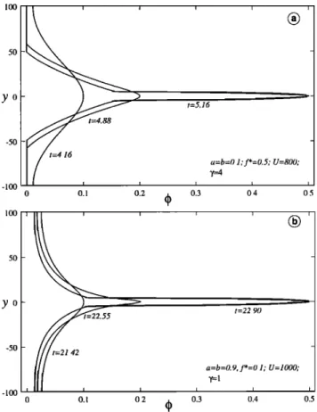
8932 BERCOVICI ET AL.: TWO-PHASE COMPACTION AND DAMAGE, 3, SHEAR 10o y 0 -5o - lOO i i i • i •=b=O.! _ _ t= 23.1 _ 0 0.1 0.2 q) 0.3 0.4 0.5 100 , , , , , a=b=0.9 5O y 0- -50 -100 t=43.9 0.3 0.4 0.5 0.9 0.7 0.5 max 0.3 0.1 0 0.1 i 0.2 i (• i i _ a=0.5 _ _ = _ _ _ 0 10 20 30 40 50 t
Figure 3. (a and b) Numerical experiments for two different
values of a; and (c) time series of 0max for three different
values of a. Values of a, b, and time/; are indicated. In all cases, b=a,X=0, anda=l.
where to is an integration constant. Although separation does occur, the time to cause complete separation (i.e., to
go entirely from •o • 0 to •o = 1) is infinite also. This
asymptotic separation can be interpreted to occur because
with a = b = 1 the interface curvature da/dcfi is finite even
when •b = 0, while the resistance to Darcy flow through the matrix becomes infinite (i.e., permeability ko4 • vanishes) as •b • 0. Thus, a• pores collapse, the surface tension driving force remains finite, while resistance to draining fluid from the pores becomes infinite, implying that the pores cannot be
entirely collapsed.
3. When a and b are neither 0 nor 1, the interface cur-
vature goes to infinity as •b • 0. Thus even as the resis- tance to Darcy flow becomes infinite as •b approaches 0, the
driving force behind draining the pores, i.e., the surface ten-
sion, also becomes infinite. In effect, the surface tension can
completely pinch the pores closed, and thus the pores can be drained, and complete separation attained, in a finite amount
of time. For example, one implicit analytic solution to (54)
• i.e.
can
be obtained
for a - b - •,
,
/; - /;o - 6(1 + 4•)arcsin(2•o - 1)
+ 12(4• + 2•o - 1)V/•o(1 - •o).
(56)
In all calculations shown in this paper we assume • - 1,
in which case the time to go from •o m 0 to •o - 1 is
/;max -- 30•r.
Some sample curves of tm•x (time for complete separa- tion) versus a (with b - a) and •o versus/; are shown in
Figure 2 for numerical solutions of (54). For a and b close to
1 separation starts gradually, accelerates, and then tapers off again toward completion. As a and b approach 0.4, this sep- aration style is reversed; that is, separation is very rapid ini- tially, tapering to a slower rate later, and accelerating again
toward completion. This illustrates the influence of the sur-
face tension "pinching" effect when the magnitude of the interface curvature reaches infinity as 4> approaches 0 or 1. As a and b approach 0, the surface tension force weakens
and separation becomes slower.
4.3.2. Numerical experiments. We next examine solu- tions of (30) and (42) using basic second order finite differ- ences, with a tridiagonal matrix solution for the finite differ- ence version of (42), and an explicit time integration (with
a time step constrained to be _< 10 -2 of the Courant time
step) for (30). Solutions are tested on various finite dif- ference grids which have between 101 and 501 points; we
find that 201 grid points are sufficient to satisfy convergence
tests.
The medium is of finite width (-100 < • < + 100), and
the boundary conditions are, again, that w - 0 at y - 4-100.
We assume that q5 obeys (30) at the boundaries as well as in
the interior (since q5 has no boundary constraints of its own).
For all cases we keep A << 1 (actually, 10-2ø); numerical
solutions to the self-separation problem with finite A are dis-
cussed by RBS2. Finally, as with all other calculations in
this paper we prescribe • - 1. We investigate only a select
number of solutions to illustrate the basic effect of varying a
(for all cases we keep b - a). All solutions are initiated with a single long-wavelength perturbation
qS(t=0) - 0.05 + 0.001 cos(7ry/100). (57)
Numerical solutions show the fluid concentrating toward
the centerline y - 0 (Figure 3 ), although this tendency is dictated by the simple initial condition (57). The effect of
decreasing a from 1 is to cause a more rapid draining of fluid
away from the wall regions (because of the surface tension
pinching effect), and thus a sharper slope along the flanks of
the porosity anomaly along with a flatter maximum (Figures
3a and 3b). However, the time for &max - max(&) to reach
values of order 1 (Figure 3c) is shortest for some intermedi-
ate value of a between 0 and 1, as predicted by the amplitude
analysis (see Figure 2). The function &max(t) also changes
BERCOVICI ET AL.' TWO-PHASE COMPACTION AND DAMAGE, 3, SHEAR 8933
tension pinching effect causes more rapid separation when 0 is near 0 and 1) as predicted by the amplitude analysis (com-
pare Figure 3c with Figure 2b, noting that the times are not the same because of different initial conditions).
5. Damage and Shear Localization
We next consider shear localization and the influence of
damage, or viscous deformational work on the interface, by allowing for f•' > 0. In this case, the relevant equations
are (30)-(33) subject to the boundary conditions (40).
5.1. Specific Equations
As noted by BRS1, the partitioning fraction f is unlikely to be constant. We can deduce one of the most basic depen- dences of f on the state of the system by considering the in-
terface work equation (33), and the case of OO/Ot = 0 which
can occur in three instances: when O = 0, when O = 1, and
at the boundary between regions where the matrix is dilat-
ing and collapsing. When O = 0 or 1, there is no interface
and thus (33) is irrelevant. When OO/Ot = 0 in the bound-
ary between dilation and collapse, O is neither 0 nor 1 and
thus (33) applies. Moreover, in this case, dc•'/dO is finite
and we can thus safely assume that AII is finite as well. In
this boundary region the left-hand side of (33) is therefore 0,
which dictates that f•': 0 as well. However, since •' > 0
when shear is imposed (regardless of O), the condition that
f•' = 0 can only be satisfied if f = 0 when OO/Ot = O. The exact dependence of f on OO/Ot cannot be inferred
from theory alone. However, we can use known constraints
on f to estimate a simple form of this dependence; in par- ticular, (1) f is positive definite and bound between 0 and 1;
(2) f is invariant to a switch of O and 1 - O (see BRS 1 for
discussion of symmetry requirements); and (3) as indicated
above, f = 0 when OO/Ot = 0. Thus, if f is to be nonzero at all, it must increase from its value of 0 at OO/Ot = 0 as 100/0l increases. However, we cannot arbitrarily as-
sume an unusual functional form for f, for example, a form
where f equals zero or reaches an extremum at some value
of OO/Ot other than OO/Ot = 0. Thus, given the above
constraints, we assume that f increases monotonically with
(OO/Ot)
2 (or
some
other
even
power
of OO/Ot
which
are
all
positive definite and invariant to a switch of O and 1 - O),
while being bound between 0 and 1. We therefore estimate
a simple monotonic relation of the form
f = 2 , (58)
where f* _< 1 and is the maximum possible value of f and
7 is a constant
that
governs
the
value
of (0O/0t)
2 at which
f approaches f*. Clearly, there are other functions that can satisfy the minimum requirements on f. However, they must
all have similar form, while the rational function given by
(58) is analytically simplest. Moreover, f certainly may de-
pend on other parameters (e.g., temperature). However, such
dependencies cannot be deduced from the above considera-
tions and most likely need to be inferred empirically. In- terestingly, however, forced-shear experiments on layers of
granular media have demonstrated that the frictional resis-
tance (related to deformational work absorbed by the sys-
tem) does indeed increase with total dilation rate rather than dilation itself, where the total dilation rate is related to the across-layer integral of OO/Ot [Gdminard et al., 1999].
With the adoption of (58), we can rewrite (33) in the
tractable form
o05
All
-dc•'
• . (59)Note that in limit of static equilibrium OO/Ot -• 0, (59)
recovers the equilibrium surface tension condition All --
-dc•'/dO (see BRS 1 and RBS2). For a constant rr the argu-
ments leading to (58) and (59) can be generalized to three
dimensions, in which case one would substitute DO/Dr for OO/Ot in these equations. In the end, our governing equa-
tions for one-dimensional damage and shear are (30)-(32) and (59).
5.2. Linear Stability Analysis
Again we examine the stability of a finite layer (with
-100 _< •t <_ +100) of constant porosity undergoing shear
and assume that O - O0 + •O•, w - •w•, and u - u0 + •u•,
where
• << 1. The only equation
that has an O(• ø) con-
tribution is the a: component of the matrix force balance (31), which, with the boundary condition that u - -+-U at
•, - +100 leads to •o - f•', where f• - U/100, and we
require that the perturbation u• - 0 at the boundaries. The
equations
that
are O(e •) are
the linearized
mass
conservation
equation (44), which is unchanged from the self-separation stability problem, and two linearized force balance equations
02el
-- f'•
001
(60)
o - (• - 0o)
Or2 Ov
o -
- ½5o)
02Wl
A(1
- O0)Wl
(61)
+ O0(
+ O0)(
- O0)
,
where (61) results after substitution of (59) into (32), Go -
G(Oo), and
3f*
t/- ---(1 - O0)2f•
2.
(62)
47
Equation (60) only governs how u• is influenced by O• but does not affect growth of porosity and therefore does not
warrant a solution. We again assume that O• and w• •
e iky+st, which leads to the dispersion relation
Gok 2
s - . (63)
+ O0( - - O0) + x
Thus shear and damage clearly accelerate the growth rate of the instability;for example, for cases in which X << 1, the
growth
rate goes
as [n q- O0(1
- •)]-1, which
approaches
8934 BERCOVICI ET AL.: TWO-PHASE COMPACTION AND DAMAGE, 3, SHEAR
If v exceeds 1 + t•/q5o, it is possible that the growth rate
can become singular at
-
+
- ½o)]
(64)100
60
and negative for larger wave numbers, in which case, the function s(k) acts as a low-pass filter, that is, only modes 4o
with sufficiently small k (large wavelength) grow, while oth- ers decay. Interpretation of this effect will be deferred to dis-
cussion of the nonlinear numerical solutions (section 5.3.2).
5.3. Nonlinear Solutions
5.3.1. Amplitude analysis. As with the self-separation
problem (section 4.3.1), we derive equations for the nonlin-
ear evolution of a self-similarly shaped porosity anomaly in an infinite medium. For consistency, we use the same shapes
for • and w employed in the self-separation problem (i.e., (47) and (50), respectively), in which case the mass conser- vation equation (30) again leads to (51). As with the self- separation amplitude analysis (section 4.3.1), the domain is
infinite (-• < •/ < •), and thus the relevant dimen-
sional
length
scale
is defined
such
that the half width • of
the porosity anomaly with amplitude •o at any time t is
Although the layer has infinite width, we can only impose finite shear by insisting that u - 4-U at some finite value of •/ - 4-L •. For consistency with the linear and numerical analyses we assign L • - 100. With these boundary con- ditions the equation governing velocity along the layer (31)
has an analytical solution:
u - U yv/1
- •o + arctan(y•o/v/1
- •o)
ß(65)
- + -
We eliminate All between (59) and (32) and then substitute
(47), (50), and (65) into the resulting equation and (after tak-
ing O/Oy of this
equation)
evaluate
it at y - 0 to obtain
0 :G((I'o) - 12(I,o(t•
+ (I'o)(1
- (I'o)2Wo
3f*•(1 - •o)4Wo
+(7 + •(• - •o)•W•)
•
3
2
+ 8• [7
+ •(1
- •o)2W•]
W•
}, (66)
whereœ
- L'(1-•o)+V/1 - •o arctan(L'•o/V/1
- •o). (67)
1000 100 10 truax 1 0.1 ?= 0 0.1 O. 0 500 1000 15(X) 2000 2500 3000 u
1 4
0 5000 10000 15000 200(X) 25000 30000 35000 40000 u....
, ...
, ...
, ....
x•xx• +++
-•-+ 10 1 (X) 10(g) 10000 ¾+1Figure 4. Time for complete separation of phases tmax ver- sus shearing velocity U for (a) several different f* (as in- dicated) with a = b -- 0.5, and7 = land (b) several different 7 (indicated) with a = b = f* = 0.9. (c) To- tal separation tmax versus shearing velocity U collapse to single curves that depend only on a (and b) when we plot
t*: (V/-•tmax
- 1) / (x/r-•tss
- 1) versus
v (using
(62) with
q50 = 0), where tss is the tmax for self-separation when f* = 0 (see Figure 2). Also t* + 1 and v + 1 are plotted in order to emphasize details on log-log axes. Curves for 27 cases are shown in Figure 4c: for each a (and b = a)
indicated, there are nine curves corresponding to all permu-
tations of 7 = 0.25, 1, 4 with f* = 0.1, 0.5, 0.9. For all
calculations, t• - 1, and the initial condition is •o - 10-3.
In deriving (66) we have assumed that since the shapes of q5 and w are approximate, then factors of the form N•o 4-
M•:(t) (where N and M are integer constants, •o is some from each other); for example, see section 4.3.1 in the dis- constant, generally either 1 or 7, and •(t) is some dependent cussion leading from (52) to (53). Equation (66) is a fifth or-
variable,
generally
either
•o or d•o/dr) are not significantly
der
polynomial
in Wo which
can
be solved
to yield
the func-
•
M) [0o 4-
Wo
(•o) (in fact, of the five possible
roots,
we choose
different
from
N[0o 4- 0(t)] or •(N +
0(t)] (de- tion
pending on which yields simpler factors) as long as N and the smallest, purely real, positive one such that (53) is recov- M are approximately equal (i.e., differ by no more than 33% ered in the limit f* -• 0). This function is then substituted
BERCOVICI ET AL.: TWO-PHASE COMPACTION AND DAMAGE, 3, SHEAR 8935 1.0 (]J• O0 0 •'"aa'•,t, aa• x x •t•C•00•'••• • • • x x •(DO 00,• •• ß • x x •OCC• 0,••• ß ß x x ([•Z)00C•• •• • • x x 0.8 0.4 0.2 0.0
0
1
2
3
4
21
22
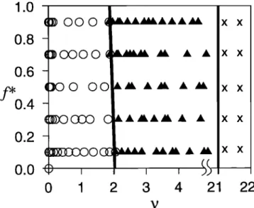
vFigure 5. Regime diagram of the different types of numer- ical solutions of the 1-D flow problem with shear and dam-
age. Three different types of solutions exist depending es- sentially only on the value •. The regimes of solutions in y-f* parameter space separated by solid lines are shown. Symbols show the location in parameter space at which so-
lutions were found. Circles indicate simple accelerated self-
separation, solid triangles indicate solutions experiencing
the tear localization, and crosses indicate solutions under-
going inhibition of phase separation or distributed damage. The diagram displays 243 solutions that have various per-
mutations of a - 0.1, 0.5, 0.9 and 7 - 0.25, 1, 25 over the
ranges 0 < f* < 0.9 and 0 _< U _< 2000. See section 5.3.2
for further discussion.
into (51) to determine the nonlinear evolution and growth of
(I>0.
In fact, the exact evolution of •0 with time differs lit-
tle in appearance from that of the self-separation problem
discussed in section 4.3.1 (see Figure 2). However, the
timescale for separation and shear localization are affected significantly by shearing and damage. This timescale is again represented by the total time tmax for •0 to go from
0 to 1, and we consider here how truax is influenced by the
parameters which represent shearing and damage (see Table 1), i.e., U, f*, and 3' (Figure 4 ).
When U = 0, all cases regardless of f* have tmax very close to the pure self-separation tmax (with f* = 0) which implies that damage has little effect without imposed shear. We refer to this self-separation tmax as tss which is only a
function of a and b (see Figure 2a).
As U • • the leading term in (66) yields
3 [3'-
•(1 - •0)2W•]
7
4 - 0, (68)
which leads to the asymptotic solution
d•0
dt = o)Wo (69)
independent
of f*; this
yields
an asymptotic
tmax
-- 1/
(see Figure 4). Thus as U increases from 0, the separation
time tmax
goes
from tss to I/v/q; given
that
the minimum
tss is approximately
102 for n - 1 (see
Figure
2a), then as
long as 7 > 10-4, an increase
in damage
and shear
(i.e., an
increase in U for f* > 0) will cause a reduction in truax, i.e.,
an acceleration in the separation of phases.
The value of U at which tmax reaches the asymptotic
value
of l/v/- q depends
on f* as well as 3' itself. An in-
crease in f* causes the tmax to reach its asymptotic value at smaller U, that is, increasing f* enhances the influence of damage, thus allowing shear to be more effective at acceler- ating phase separation (Figure 4). While an increase in 3' de- creases the asymptotic value of tmax (i.e., allows for greater possible acceleration of phase separation), it also increases
the value of U at which this tmax is attained (i.e., decreases
the effectiveness of damage and shear).
The influence of damage on the rate of phase separation
can be most succinctly summarized by noting that tmax ver-
sus U curves for different f*, and 3' (but with the same a and
b) can be very nearly collapsed on to the same curve if we
assume that
_ I (
tmax
-- • q- tss(a,
b)
F(•,
a,
b) (70)
(Figure 4c). However, since the amplitude analysis assumes a single self-similar shape for q5 that narrows with time, it
cannot account for the low-pass filter effect of y > 1 +
predicted in the linear stability analysis. Overall, the ampli- tude analysis predicts a considerable acceleration of phase separation by the addition of shear and damage.
5.3.2. Numerical experiments. We finally explore nu-
merical solutions of (30)-(32) and (59), using, as with the
self-separation problem, a finite difference scheme. As with the linear stability problem and previous numerical experi-
ments, our dimensionless domain is-100 _< y _< +100. We
employ the same initial and boundary conditions as stated in
section 4.3.2, with the additional condition that u - +U at y - 4-100.
For simplicity, we do not fully explore all parameter space (which is, in fact, seven-dimensional, i.e., defined by a, b, U, 3', f*, n, and A, not including initial conditions) and thus keep certain parameters fixed. As with all previous calcula-
tions, we setA << 1, n - 1, andb - a. In the end, the
parameter space we explore is four-dimensional, over a, f*,
U, and 3'; however, it is often more convenient to refer to instead of U (using q•0 - 0.05 in (62); also see Table 1).
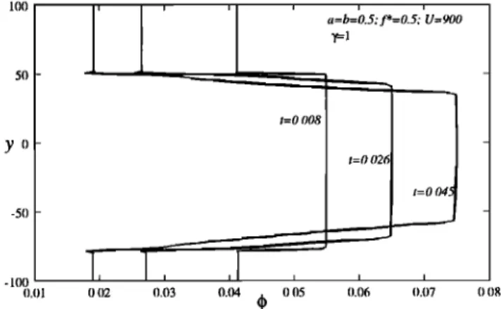
The numerical solutions reveal three basic regimes which essentially depend only on •, as displayed in Figure 5 . These regimes are as follows:
1. For "low" values of t,, (t,, _< 2) the porosity field col- lapses essentially in the same manner as the surface ten- sion driven self-separation problem (see Figure 3). Only the growth rate of q•max, the peak porosity value, appears to be affected by changes in U (or •,), f*, and 3', as predicted by the stability and amplitude analyses (Figure 6 ). Thus, in this
regime, changes in the shear and damage parameters U, f*, and 3' that cause an increase in t,, induce only an acceleration
of the self-separation effect. We refer to this regime as the "accelerated separation" regime of solutions. As • exceeds