HAL Id: hal-00316849
https://hal.archives-ouvertes.fr/hal-00316849
Submitted on 1 Jan 2001
HAL is a multi-disciplinary open access
archive for the deposit and dissemination of
sci-entific research documents, whether they are
pub-lished or not. The documents may come from
teaching and research institutions in France or
abroad, or from public or private research centers.
L’archive ouverte pluridisciplinaire HAL, est
destinée au dépôt et à la diffusion de documents
scientifiques de niveau recherche, publiés ou non,
émanant des établissements d’enseignement et de
recherche français ou étrangers, des laboratoires
publics ou privés.
Rarefied gas flows through meshes and implications for
atmospheric measurements
J. Gumbel
To cite this version:
J. Gumbel. Rarefied gas flows through meshes and implications for atmospheric measurements.
An-nales Geophysicae, European Geosciences Union, 2001, 19 (5), pp.563-569. �hal-00316849�
Rarefied gas flows through meshes and implications
for atmospheric measurements
J. Gumbel
Department of Meteorology, Stockholm University, 10691 Stockholm, Sweden Received: 16 October 2000 – Revised: 13 March 2001 – Accepted: 3 April 2001
Abstract. Meshes are commonly used as part of instruments
for in situ atmospheric measurements. This study analyses the aerodynamic effect of meshes by means of wind tunnel experiments and numerical simulations. Based on the Direct Simulation Monte Carlo method, a simple mesh parameteri-sation is described and applied to a number of representative flow conditions. For open meshes freely exposed to the flow, substantial compression effects are found both upstream and downstream of the mesh. Meshes attached to close instru-ment structures, on the other hand, cause only minor flow disturbances. In an accompanying paper, the approach de-veloped here is applied to the quantitative analysis of rocket-borne density measurements in the middle atmosphere.
Key words. Atmospheric composition and structure
(instru-ments and techniques; middle atmosphere – composition and chemistry)
1 Introduction
Meshes are an essential part of many instruments used in middle atmospheric research. Typical applications comprise mesh-like electrodes in ionisation gauges or charge sensors (e.g. Thrane, 1986; Giebeler and Lübken, 1995; Havnes et al., 1996). In these instruments, meshes provide a direct elec-trical contact to the ambient plasma, while at the same time allowing a continuous flow of air through the measurement volume. Nevertheless, meshes introduce major disturbances to the atmospheric flow. When not taken into account appro-priately, these disturbances can strongly affect measurement accuracies, in particular, for sounding rocket experiments at supersonic speed.
Aerodynamic effects on sounding rocket experiments have been discussed, for example, by Bird (1988) and Gumbel (2001). Considering phenomena, such as airglow, noctilu-cent clouds or polar mesosphere summer echoes, the alti-tude range of the upper mesosphere and lower thermosphere
Correspondence to: J. Gumbel ([email protected])
(70–120 km) is of particular interest for investigations utilis-ing soundutilis-ing rockets (e.g. Meriwether, 1989; Thomas, 1991; Cho and Röttger, 1997). From an aerodynamic point of view, this altitude range just falls into the transition regime where the atmospheric molecular mean free path is compa-rable to typical instrument dimensions. As a consequence, aerodynamic analysis is complicated, since computational tools from neither continuum fluid dynamics nor free molec-ular flow can be applied. A numerical tool which has been successfully applied to flows in the transition regime is the Direct Simulation Monte Carlo (DSMC) technique by Bird (1994). Based on this technique, the present paper describes a parameterisation of mesh flows and applies it to a num-ber of examples representative for atmospheric measurement conditions. While these examples focus on sounding rocket flights, many conclusions are applicable to flows at lower al-titudes, e.g. mesh probes flown on aircraft.
The aerodynamic effect of meshes depends strongly on in-strument geometry and flow condition. Two limiting cases can be distinguished and are analysed here: a mesh which is freely exposed to the atmospheric flow and an attached mesh which is part of a closed instrument structure. In ad-dition, the effect of different rarefaction of the flow is dis-cussed. In an accompanying paper by Rapp et al. (2001), the results obtained here are applied to the quantitative analysis of rocket-borne density measurements in the mesosphere and lower thermosphere.
2 Wind tunnel study
Experimental data on the flow through meshes has been ob-tained during wind tunnel studies at the Laboratoire d’Aéro-thermique du CNRS in France (Gumbel, 2001). The Facil-ity for Rarefied, Supersonic and Reactive Flows provides the unique opportunity of quantitatively studying rarefied flows (Allègre, 1992). Mesh studies have been performed for the freestream conditions p∞ = 2.6 Pa, c∞ = 678 m s−1 and
564 J. Gumbel: Rarefied gas flows through meshes metal ring (thickness 1 mm) mesh (transmission 76%) 28 mm
Fig. 1. Geometry of the mesh studied in the wind tunnel.
sphere model, this corresponds to a molecular mean free path of λ∞=0.62 mm.
Figure 1 shows the mesh that was investigated during these studies. It is a flat structure mounted on a metal ring; the in-dividual bridges have a width of 0.10 mm and are equally spaced at a distance of 0.80 mm. The resulting geometrical transmissivity is 76%. (The geometrical transmissivity can be determined with high accuracy by measuring the trans-mission of light through the mesh.)
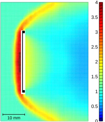
In the wind tunnel, flow density fields were measured by electron beam induced fluorescence (Gumbel, 2001). The spatial resolution is about 1 mm, as determined by the diam-eter of the electron beam. Resulting density fields are given relative to the freestream density rather than in absolute units. The accuracy of the normalised density is about 10%. Fig-ure 2 presents the density field obtained for the wind tunnel flow through the mesh in Fig. 1.
Two striking features are observed: firstly, despite the trans-missivity of 76%, a strongly perturbed region with compres-sion exceeding 3 builds up in front of the mesh. Secondly, a compressed region is found behind the mesh. This pen-etration of enhanced densities is in obvious contrast to the rarefied wake conditions behind solid objects. For the mesh, rarefied conditions are found only at larger downstream dis-tances from the object.
The transmissivity of 76% determines the probability of a molecule hitting the mesh structure upon passage through the mesh plane. Although this probability is low for an individ-ual molecule, the mesh can give rise to a strong perturbation of the flow. This is governed by intermolecular collisions; a shock structure develops and all molecules are strongly in-fluenced.
3 Model description
The DSMC method for the analysis of rarefied flows has been described comprehensively by Bird (1994). The ap-proach is microscopic and analyses the fate of individual gas molecules. Macroscopic flow properties, such as density, temperature or velocity fields are obtained as appropriate av-erages by tracing the paths and the interactions of representa-tive molecules. The numerical simulations presented here are based on a DSMC code developed at Stockholm University (Gumbel, 2001). 10 mm 0 0.5 1 1.5 2 2.5 3 3.5 4
Fig. 2. Density field N/N∞measured around the mesh in the wind
tunnel. Freestream conditions are p∞=2.6 Pa, c∞=678 m s−1
and T∞=71 K, which corresponds to a molecular mean free path
of 0.62 mm. No data was obtained close to the mesh surface.
The DSMC approach can readily describe interactions be-tween gas and mesh on a molecular level. However, a de-tailed simulation of all mesh elements is usually not feasi-ble. Typical sizes of DSMC sampling grids must be small enough to resolve gradients in the flow. For a complete sim-ulation of the mesh geometry with all ridges and openings, this would require grid sizes smaller than the diameter of in-dividual mesh wires. Furthermore, since the detailed mesh structure is usually not cylindrically symmetric, a full 3-D simulation would be required. This would require signifi-cantly more programming and computational efforts than the cylindrically symmetric (2-D) simulations presented here.
For these reasons, a parameterisation has been developed, which is based on the unresolved geometric transmissivity of the mesh. For the mesh in Fig. 1, this transmissivity is 76%. Hence, from the individual simulated molecules crossing the plane of the mesh, 76% are transmitted without interaction, while 24% are reflected. The mesh considered here is as-sumed to be completely flat. As a consequence, the transmis-sivity is independent of the incidence angle, and the velocity distribution of reflected molecules is in accordance with a diffusely reflecting flat surface. The mesh surface temper-ature is assumed to be 300 K, which is justified by good thermal contact between the mesh and the bulk wind tunnel structure. More complicated mesh structures (e.g. consist-ing of round wires) can be simulated when suitable descrip-tions of appropriate angular dependencies are introduced in the model.
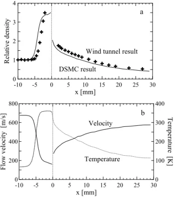
-10 -5 0 5 10 15 20 25 30 x [mm] 0 1 2 3 Relat ive de ns ity
Wind tunnel result DSMC result a -10 -5 0 5 10 15 20 25 30 x [mm] 0 200 400 600 800 Fl ow v el oc ity [m /s ] 0 100 200 300 400 T emperat ur e [K ] Temperature Velocity b
Fig. 3. Flow conditions along the symmetry axis in Fig. 2. (a) Mea-sured and simulated density, (b) simulated temperature and axial velocity component.
4 Flow through free meshes
Applying the Stockholm DSMC model, Fig. 3a shows a com-parison between the simulation and the wind tunnel result along the symmetry axis of Fig. 2. In addition to the parame-terised mesh, the solid ring supporting the mesh has also been included in the simulation. The model succeeds in reproduc-ing the basic structure of the flow field, includreproduc-ing the up-stream shock, the density enhancement behind the mesh and the gradual downstream density decrease. However, quan-titative agreement is limited. The DSMC parameterisation slightly underestimates the effective mesh transmission. This causes the shock to extend too far upstream and the densities to be too low downstream. Simulations have been performed for other meshes at the same flow conditions. These show that the measured density field is reproduced best when a ge-ometric mesh transmissivity of 82% instead of 76% is used in the simulation. This enhanced transmission may be ex-plained, for example, by the mesh structure not being com-pletely flat and hence, allowing for forward scattering to oc-cur. Further insight into the details of the transmission will require DSMC studies that spatially resolve the small scale flow through the mesh structures.
Figure 3b shows the DSMC results for the axial flow ve-locity and the temperature along the symmetry axis. Both the deceleration of the flow and a strong temperature perturba-tion can be seen. In front of the mesh, the mean velocity con-sists of contributions from incident and reflected molecules and it decreases below 200 m s−1. Through the plane of the
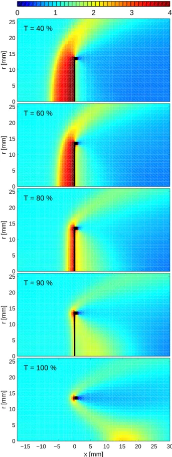
mesh, it is dominated by penetrating molecules with veloc-ity components in forward direction. Nevertheless, as can be shown by tracing individual molecules, a finite probability exists for molecules to penetrate the mesh in the upstream direction. Further applying the Stockholm DSMC model, Figs. 4 and 5 illustrate the aerodynamic effects of meshes for a wide range of conditions. Meshes with geometric transmis-sivity between 40% and 100% have been simulated. In the latter case, no mesh is present and only a solid ring with a thickness of 1 mm disturbs the flow. Both figures represent typical conditions during sounding rocket flights in the alti-tude range 75–85 km. Freestream velocity and temperature are c∞=800 m s−1and T∞=180 K. Freestream pressures
are p∞=4.1 Pa in Fig. 4 and p∞=0.41 Pa in Fig. 5,
cor-responding to molecular mean free paths of λ∞=1 mm and
10 mm, respectively. Hence, in the former case, λ∞is of the
order of the size of the mesh elements; in the latter case, λ∞
is of the order of the entire mesh size.
As expected, magnitude and extent of the compression in front of the mesh decrease with increasing transmissivity. Di-rectly behind the mesh, the situation is more complicated; the largest density enhancement is found for an intermediate transmissivity around 80%. In terms of a downstream en-hancement, this transmissivity value provides an optimum combination of compression in front of the mesh and gas penetration through the mesh. Comparing Figs. 4 and 5, dis-turbances by the mesh smear out and become, in general, less pronounced as the flow becomes more rarefied.
In addition, the solid ring supporting the mesh exerts a substantial influence on the flow. In particular, for the case λ∞ = 1 mm, strong flow disturbances remain even when
the mesh is removed (transmission = 100%). Each part of the ring causes a shock structure; on the symmetry axis these shock structures interfere and give rise to a distinct local den-sity maximum ∼15 mm downstream of the ring. In a sense, the ring can be considered as an “aerodynamic lens” that en-hances the flow density close to a “focal point”. The position of this point is determined by the shock geometry, in partic-ular, by the Mach number and the Mach angle of the flow. A recent example for this flow geometry is a rocket-borne ring electrode flown by Havnes et al. (2001) upstream of a dust detector.
5 Flow through attached meshes
The picture changes when additional objects influence the flow behind the mesh. The limiting case consists of closed structures, such as detectors boxes, attached to the mesh. Such structures have been used, for example, in connection with rocket-borne ionisation gauges or particle detectors (e.g. Hillert et al., 1994; Havnes et al., 1996). For these structures in a steady state flow, there is obviously no net mass flux through the mesh. DSMC results for a flow towards a closed tube with and without an attached mesh are given in Fig. 6. The mesh is the same as in Figs. 1–3; freestream flow
condi-566 J. Gumbel: Rarefied gas flows through meshes 0 5 10 15 20 25 T = 40 % r [mm] 0 1 2 3 4 0 5 10 15 20 25 T = 60 % r [mm] 0 5 10 15 20 25 T = 80 % r [mm] 0 5 10 15 20 25 T = 90 % r [mm] −15 −10 −5 0 5 10 15 20 25 30 0 5 10 15 20 25 T = 100 % x [mm] r [mm]
Fig. 4. Simulated density fields for meshes of different
transmis-sivity and a molecular mean free path λ∞ = 1 mm. Other flow
parameters are c∞=800 m s−1and T∞=180 K.
0 5 10 15 20 25 T = 40 % r [mm] 0 1 2 3 4 0 5 10 15 20 25 T = 60 % r [mm] 0 5 10 15 20 25 T = 80 % r [mm] 0 5 10 15 20 25 T = 90 % r [mm] −15 −10 −5 0 5 10 15 20 25 30 0 5 10 15 20 25 T = 100 % x [mm] r [mm]
0 5 10 15 20 with mesh r [mm] 0 1 2 3 4 5 −10 0 10 20 30 0 5 10 15 20 without mesh r [mm] x [mm]
Fig. 6. Simulated density fields N/N∞for the flow towards a
semi-closed instrument structure (a) with and (b) without attached mesh.
Freestream conditions are the same as in the wind tunnel p∞ =
2.6 Pa, c∞=678 m s−1and T∞=71 K.
tions are again the same as in the wind tunnel. For this geom-etry, the presence of the mesh does not substantially alter the flow. The density near the bottom of the tubes is enhanced by a factor of 4.6.
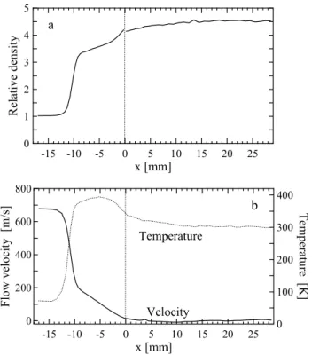
Figure 7 shows the variation of density (7a), and tempera-ture and axial velocity (7b) along the symmetry axis for the mesh case. All quantities experience a quick change at the front of the disturbed region. Then there are smaller changes towards the mesh with rather homogeneous conditions in-side the tube. From the mesh to the bottom wall, the density increases by ∼15%. Inside the tube, the gas is essentially thermalised to the wall temperature of 300 K.
The compression of 4.6 in the tube can be compared to the compression limit for a deep tube (Pitot tube) in a continuum flow. For this case, the Rayleigh-Pitot relation (e.g. Shapiro, 1954) gives a result of 5.0. Hence, the detector geometry and flow conditions considered here deviate by less than 10% from the Pitot limit.
As a comparison to more rarefied conditions, Fig. 8 shows the corresponding DSMC results for p∞ =0.03 Pa, which
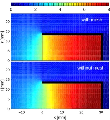
are representative for an atmospheric altitude of about 100 km. For these conditions, the molecular mean free path is 0.13 m and no sharp structures exist. Both with and without mesh, there are significant density gradients throughout the tube. As opposed to the denser flow, the mesh has now a clear ef-fect, giving rise to a jump in density at the tube entrance. Also, the mesh reduces the compression near the back wall inside the box.
-15 -10 -5 0 x [mm]5 10 15 20 25 0 1 2 3 4 Relat ive de ns ity a -15 -10 -5 0 5 10 15 20 25 x [mm] 0 200 400 600 800 Fl ow v el oc ity [ m /s ] 0 100 200 300 400 T em pe ra tur e [K ] Temperature Velocity b
Fig. 7. Simulated flow conditions along the symmetry axis for the flow with mesh in Fig. 6. (a) Density, (b) simulated temperature and axial velocity component.
6 Conclusions
Meshes are used in a wide range of atmospheric instrumen-tation. An aerodynamic analysis of their flow effect is im-portant, since they can cause significant disturbances within in situ measurements. Even for meshes of high geomet-ric transmissivity, large flow perturbations develop. There is strong upstream compression, and penetrating molecules lead to regions of enhanced density even downstream of the mesh. Considering a proper formulation of boundary condi-tions, a simulation of mesh flows in conventional fluid dy-namics is difficult. On the other hand, the molecular formu-lation of DSMC flow analysis can readily describe gas/mesh interactions. However, a detailed simulation of the complete mesh geometry will, in many cases, be prohibited by con-straints in the computing and programming resources. There-fore, a simple parameterisation has been developed for use in DSMC codes: for an individual molecule approaching the mesh, the penetration probability is determined by the mean geometric transmissivity of the mesh. Angle-dependent trans-mission probabilities and reflection properties can be defined. In the examples presented here, the easiest case of an in-finitely flat mesh was used.
Simulations have been carried out for flow conditions rep-resentative for sounding rocket experiments in the mesopause region. The largest effects are found for open mesh structures which are directly exposed to the flow. In the other limiting case of closed structures without net flux through the mesh, the aerodynamic effect of the mesh is small and usually
neg-568 J. Gumbel: Rarefied gas flows through meshes −10 0 10 20 30 0 5 10 15 20 with mesh r [mm] x [mm] 0 2 4 6 8 −10 0 10 20 30 0 5 10 15 20 without mesh r [mm] x [mm]
Fig. 8. As Fig. 6, but for the more rarefied atmospheric flow
con-ditions representative for an altitude of ∼100 km: p∞= 0.03 Pa,
c∞=800 m s−1and T∞=180 K.
ligible for near continuum conditions. As the flow becomes more rarefied, the effect of free meshes becomes less pro-nounced. The effect of attached meshes, on the other hand, increases with increasing rarefaction. In the accompanying paper by Rapp et al. (2001), the flow through a rocket in-strument is discussed, which falls in-between the two lim-iting cases of free mesh and attached mesh. The DSMC technique presented here is applied to obtain aerodynamic corrections to density measurements performed with that in-strument. The applicability of the DSMC approach to such a quantitative analysis has been confirmed by comparison to complementary density measurements performed simultane-ously.
In addition to applications in data analysis, the simulations presented here can serve as a valuable tool when designing and characterising new atmospheric experiments. Some ex-amples can be mentioned: shielding meshes should be de-signed to provide a reasonable compromise between high transmissivity for air flow and low “transmissivity” for elec-tric fields. The flow characteristics through meshes attached to closed detectors (Sect. 5) can be changed substantially by introducing vending holes in the detector structure. The con-cept of aerodynamic focussing by ring structures (Sect. 4) can be utilised to enhance the flow through measurement vol-umes.
When applied in atmospheric instruments, meshes often serve as electrodes in connection with ion density or particle measurements. Electric and magnetic fields applied in such instruments can be included in the DSMC equations of mo-tion. Subject to electromagnetic interactions, disturbances in
ion number density can largely differ from aerodynamic ef-fects on the neutral flow. This is even more true for the distri-bution of electrons. Sugimura and Vogenitz (1975) have dis-cussed basic modelling techniques for ion flows. Horányi et al. (1999) showed how the fate of clusters or particles in the air flow towards a payload can be treated. These methods can readily be combined with the DSMC mesh parameterisation described here. This will be essential for a comprehensive analysis of many ion and particle measurements performed in the Earth’s middle atmosphere.
Acknowledgements. The help of J. Allègre, J.-C. Lengrand and the
staff of the Laboratoire d’Aérothermique du CNRS made the wind tunnel experiments possible. I also wish to thank M. Rapp and C. Unckell for their support during experiments and data analysis. The European Commission funded the wind tunnel experiments un-der the Access to Large Scale Facilities activity of the Training and Mobility of Researchers program. Also, support from the Swedish National Space Board is highly appreciated.
The Editor in Chief thanks R. Goldberg and M. Horányi for their help in evaluating this paper.
References
Allègre, J., The SR3 low density wind tunnel. Facility capabilities and research development, Rep. AIAA 92-3972, American Insti-tute of Aeronautics and Astronautics, Reston, VA, 1992. Bird, G. A., Aerodynamic effects on atmospheric composition
mea-surements from rocket vehicles in the mesosphere, Planet. Space Sci., 36, 921–926, 1988.
Bird, G. A., Molecular gas dynamics and the direct simulation of gas flows, Oxford University Press, Oxford, 1994.
Cho, J. Y. N. and Röttger, J., An updated review of polar meso-sphere summer echoes: Observation, theory, and their relation-ship to noctilucent clouds and subvisible aerosols, J. Geophys. Res., 102, 2001–2020, 1997.
Giebeler, J. and Lübken, F.-J., Density and temperature measure-ments in the lower thermosphere with the CONE instrument, ESA SP-370, 101–106, 1995.
Gumbel, J., Aerodynamic influences on atmospheric in situ mea-surements from sounding rockets, J. Geophys. Res., in print, 2001.
Havnes, O., Troim, J., Blix, T., Mortensen, W., Naesheim, L. I., Thrane, E., and Tønnesen, T., First detection of charged dust par-ticles in the Earth’s mesosphere, J. Geophys. Res., 101, 10839– 10847, 1996.
Havnes, O., Brattli, A., Aslaksen, T., Singer, W., Latteck, R., Blix, T., Thrane, E., and Troim, J., First common volume observa-tion of layered plasma structures and polar mesospheric summer echoes by rocket and radar, Geophys. Res. Lett., 28, 1419–1422, 2001.
Hillert, W., Lübken, F.-J., and Lehmacher, G., TOTAL: a rocket-borne instrument for high resolution measurements of neutral air turbulence during DYANA, J. Atmos. Terr. Phys., 56, 1835– 1853, 1994.
Horányi, M., Gumbel, J., Witt, G., and Robertson, S., Simulation of rocket-borne particle measurements in the mesosphere, Geophys. Res. Lett., 26, 1537–1540, 1999.
Meriwether, Jr., J. W., A review of the photochemistry of selected nightglow emissions from the mesopause, J. Geophys. Res., 94, 14629–14646, 1989.
ments in the middle atmosphere, Ann. Geophysicae, this issue, 2001.
Shapiro, A., The dynamics and thermodynamics of compressible fluid flow, Vol. I, The Ronald Press Company, New York, 1954. Sugimura, T. and Vogenitz, F. W., Monte Carlo simulation of ion
collection by a rocket-borne mass spectrometer, J. Geophys.
Thomas, G. E., Mesospheric clouds and the physics of the mesopause region, Rev. Geophys., 29, 553–575, 1991.
Thrane, E. V., DC-probe measurements in the middle atmosphere, in Middle Atmosphere Program, Handbook for MAP, Vol. 19, R. A. Goldberg (Ed.), pp. 138–154, 1986.