HAL Id: hal-00961075
https://hal.archives-ouvertes.fr/hal-00961075v2
Submitted on 19 Mar 2014HAL is a multi-disciplinary open access
archive for the deposit and dissemination of sci-entific research documents, whether they are pub-lished or not. The documents may come from teaching and research institutions in France or abroad, or from public or private research centers.
L’archive ouverte pluridisciplinaire HAL, est destinée au dépôt et à la diffusion de documents scientifiques de niveau recherche, publiés ou non, émanant des établissements d’enseignement et de recherche français ou étrangers, des laboratoires publics ou privés.
Sedimentary stylolite networks and connectivity in
Limestone: Large-scale field observations and
implications for structure evolution
Leehee Laronne Ben-Itzhak, Einat Aharonov, Ziv Karcz, Maor Kaduri,
Renaud Toussaint
To cite this version:
Leehee Laronne Ben-Itzhak, Einat Aharonov, Ziv Karcz, Maor Kaduri, Renaud Toussaint. Sedi-mentary stylolite networks and connectivity in Limestone: Large-scale field observations and im-plications for structure evolution. Journal of Structural Geology, Elsevier, 2014, pp.online first. �10.1016/j.jsg.2014.02.010�. �hal-00961075v2�
1
Sedimentary stylolite networks and connectivity in
2
Limestone: Large-scale field observations and
3
implications for structure evolution
4 5
Laronne Ben-Itzhak L.1, Aharonov E.1, Karcz Z.2,*,
6
Kaduri M.1,** and Toussaint R.3,4
7 8
1 Institute of Earth Sciences, The Hebrew University, Jerusalem, 91904, Israel
9
2
ExxonMobil Upstream Research Company, Houston TX, 77027, U.S.A
10
3 Institut de Physique du Globe de Strasbourg, University of Strasbourg/EOST, CNRS, 5 rue
11
Descartes, F-67084 Strasbourg Cedex, France.
12
4 Centre for Advanced Study at The Norwegian Academy of Science and Letters, Drammensveien
13
78, 0271 N-Oslo, Norway.
14 15
* Currently at Delek Drilling LP
16
** Currently at ISTerre, University J. Fourier – Grenoble I, BP 53, F-38041 Grenoble, France
17 18 19 20 21
Abstract
22Stylolites are rough surfaces, formed by localized rock dissolution, and prevalent in 23
carbonates and other sedimentary rocks. Their impact on porosity and permeability, and capacity 24
to accommodate compactive strain, are well documented. This paper presents a meso-scale field 25
study on sedimentary stylolites in carbonates, characterizing large-scale distributions of 26
stylolites, including measurements conducted on longer than kilometer-long stylolites. Our field 27
study suggests that on large-scales connections between stylolites become important. Since 28
connectivity, and also lack of connectivity, are expected to play a significant role in strain 29
accommodation and hydraulic rock properties, we suggest that large-scale analysis may require a 30
new characterization scheme for “stylolites populations”, based on their connectivity. We 31
therefore divide sedimentary stylolite populations into three end-member types, which are 32
correlated with the three possibilities for percolation of such systems: isolated stylolites (with 33
zero percolation/connectivity), long-parallel stylolites (with 2-dimensional 34
percolation/connectivity), and interconnected stylolite networks (with 3-dimensional 35
percolation/connectivity). New statistical parameters and measures are devised and used to 36
quantitatively characterize the different population types. Schematic mechanistic models are then 37
offered to explain the evolution of the three end-member connectivity-classes. In addition we 38
discuss the effect on fluid flow of the different population types. 39
40 41 42
1. Introduction
4344
Stylolites are rough surfaces of dissolution, common in sedimentary rocks and especially 45
prominent in carbonates. They are lined by a thin layer of relatively insoluble particles, mainly 46
clay minerals, oxides, and organic matter, that are thought to accumulate while the major 47
constituent of the rock, which is more soluble (e.g. carbonate, quartz) dissolves away (Stockdale, 48
1922, Park and Schot, 1968, Kaplan, 1976, Railsback, 1993). Stylolites are known to affect fluid 49
flow in opposing ways: On the one hand, stylolites are often associated with reduced 50
permeability - material that dissolves at the stylolite precipitates in adjacent pores, forming 51
“tight” units (Wong and Oldershaw, 1981, Tada and Siever, 1989, Finkel and Wilkinson, 1990, 52
Ehrenberg, 2006) that are important in management of hydrocarbon aquifers and reservoirs 53
(Corwin et al., 1997). In other cases, stylolites may enhance porosity and permeability in their 54
vicinity, in particular their tips (Carozzi and Vonbergen, 1987, Raynaud and Carrioschaffhauser, 55
1992) and sometimes fluid flow is observed along stylolitic surfaces (Wong and Oldershaw, 56
1981, Rye and Bradbury, 1988, Heap et al., 2014). In addition to their hydraulic role, stylolites 57
are also known to accommodate large compactive strains (Tada and Siever, 1989), playing a key 58
role in the evolution of mechanical rock properties, and the overall compactive strain of rocks. 59
60
Stylolite formation is attributed to localized Pressure Solution (PS). PS is broadly defined as 61
dissolution and re-precipitation driven by spatial variations in chemical potential along grain 62
surfaces: regions with high chemical potential dissolve, the dissolved material is transported 63
through the fluid phase, and precipitates in regions where the chemical potential is lower. 64
Variations in the chemical potential arise due to spatial variations in stress, plastic and elastic 65
strain energies, crystal orientation and interface curvature (Deboer, 1977, Lehner, 1995, 66
Paterson, 1995, Shimizu, 1995). The chemical potential can be extended to an electrochemical 67
potential (Greene et al., 2009) where spatial variations in surface charge are considered as well. 68
Clays and organic matter are also thought to play an important role in the PS process (Heald, 69
1956, Thomson, 1959, Sibley and Blatt, 1976, Gruzman, 1997), and their distribution and 70
content are believed to affect the rate of PS (Hickman and Evans, 1995, Renard et al., 2001) and 71
the degree of PS localization on stylolites (Heald, 1955, 1956, Engelder and Marshak, 1985, 72
Marshak and Engelder, 1985). How clays, phyllosilicates, and organic matter enhance PS is not 73
fully understood, and suggestions include purely physical (propping grain contacts) (Weyl, 74
1959), chemical (varying pH) (Thomson, 1959), electrochemical (solute gradients amplified by 75
clay electric charge) (Walderhaug et al., 2006) effects, or a combination of the above. 76
Key models for stylolite formation view them as isolated and spatially limited surfaces (e.g. 77
Fletcher and Pollard (1981); Stockdale (1922)). However, in the field they are rarely “isolated”, 78
but rather appear to be closely related to other stylolites and structures (primarily Mode I and 79
Mode II fractures) (Peacock and Sanderson, 1995, Smith, 2000). Perhaps because of the scarcity 80
of isolated stylolites, and the difficulty in determining their terminations when not isolated, there 81
is very limited literature on stylolites' lateral extent. Stylolites were traced in limestone for over 82
50 m by Park and Schot (1968), and Safaricz (2002) followed single stylolites for 8.5m and 83
dissolution seams for over 800 m. An often-cited linear relationship between stylolite length and 84
thickness (either amplitude or seam thickness), is thus based on a handful of field studies 85
(Stockdale, 1922, Mardon, 1988, Benedicto and Schultz, 2010, Nenna and Aydin, 2011) though a 86
theoretical rationale for it is fairly well understood (Aharonov and Katsman, 2009). 87
Most stylolites seem to have been studied on "small" outcrops or, in the case of the oil and 88
gas industry, on cores. A few exceptions are the field-wide studies of (Stockdale, 1922, 89
Railsback, 1993, Andrews and Railsback, 1997, Safaricz, 2002, Safaricz and Davison, 2005). 90
Stylolites, like fractures, are "very large" in one dimension but "very small" in another 91
dimension. Their thickness is of the order of centimeters at most, so they are impossible to 92
resolve with standard seismic techniques. In order to determine the large-scale distribution of 93
stylolites (needed to assess for example reservoir performance or compactive basin-scale strain) 94
the geometry and hydraulic properties of the centimeter-scale observation made routinely on 95
cores needs to be upscaled to the kilometer-scale structure, which is always a challenging task. 96
To devise a robust upscaling methodology, the cm-scale structure needs to be linked to the km-97
scale structure through an adequate analog-outcrop, as is common in the petroleum industry. 98
Only through such an analog can upscaling parameters and workflows be tested and confirmed. 99
Such studies were previously done on fractures (Dawers et al., 1993, Main, 1996, Cello, 1997, 100
Willemse, 1997, Bour and Davy, 1998, McLeod et al., 2000), and led to basic understanding 101
regarding the relationship between aperture and length (Vermilye and Scholz, 1995) and the 102
formation and connectivity of fractures (Segall and Pollard, 1980, Cartwright et al., 1995, Gupta 103
and Scholz, 2000). The present work performs a similar multi-scale study on sedimentary 104
stylolites populations, aiming to quantify their distributions and connectivity and provide a step 105
towards understanding their large-scale effects. 106
107
The connectivity of stylolites may be important both when they act as flow conduits, and in 108
the opposite case, when they act as barriers. Their impact on large-scale flow properties can be 109
understood using ideas from percolation theory (for a review on percolation see e.g. Bunde and 110
Havlin (1991)). Percolation theory is a mathematical theory that addresses the question of the 111
connectivity and conductivity within a composite material, composed of “black” defects placed 112
within a “white” matrix. In the percolation “game” the black defects are typically assigned a 113
different conductivity than their host white matrix, and percolation theory predicts electrical 114
conductivity and resistivity of the composite black-white material (e.g. McLachlan et al. (1990)). 115
The black defects are said to “percolate” when one can trace along black parts only (without 116
“stepping” into white parts) from any side of the matrix body to any other. When black defects 117
are conductive “percolation” is accompanied by abrupt enhancement of the conductivity of the 118
matrix relative to a state of no percolation. The opposite game is just as simple – if black defects 119
have high resistivity (low conductivity), percolation of conducting whites controls conductivity. 120
Percolation of conduction whites is lost when there are enough black defects, or when blacks are 121
distributed in such a way that whites are disconnected.
122
In line of the above percolation picture, we suggest to envision stylolites as “penny-shaped” 123
surfaces with a different fluid conductivity (higher or lower) than their host rock. These surfaces 124
can have different radii and they can be oriented in different angles to each other and can be 125
envisioned as “black” defects in a “white” host rock. 126
127
Percolation or connectivity of the stylolite surfaces are then expected to occur in one of three 128
end-member ways: 129
I: Isolated surfaces – no percolation: If the radii of surfaces is small, and if there are not many
130
surfaces within the region, then the surfaces may not cross each other and remain isolated from 131
one another. In that case there is no percolation of surfaces from any side of the box to any other. 132
This system is below the percolation threshold. 133
II: Parallel surfaces - 2D percolation: if surfaces are virtually infinite and parallel, they create a
134
layered structure. In this case both surfaces and host rock percolate in the direction parallel to the 135
surfaces, but neither of them percolates in the direction perpendicular to the surfaces. If the 136
surfaces have higher conductivity than the host rock they will enhance conductance in the 137
surface-parallel direction and will not affect the perpendicular direction. Instead, if the surfaces 138
have lower conductivity they will not affect the surface-parallel direction yet will act as barriers 139
for conductance in the perpendicular direction. In this case percolation is anisotropic and so is 140
conductance. 141
III: Networks of interconnected surfaces - 3D percolation: when there are enough surfaces, and
142
they have a distribution of orientations, they will connect to one another and allow percolation in 143
all three dimensions. 144
In order to analyze the 3D connectivity of stylolites with the above framework in mind we 146
devised new statistical characterization tools that quantify the morphology of stylolite 147
populations. We use our new tools in three well-exposed localities, chosen from a collection of 148
17 field-sites (Table 1). These sites were chosen due to their good exposure, and also because 149
they exemplify the 3 end-member surface-connectivity/percolation possibilities presented above. 150
The Supplementary provides location, geological setting and general description of stylolites 151
exposed in the other 14 localities. Most of these are field-sites that we studied and a few are 152
places described in the literature and studied by others. 153 154
2. Methods
155 156 2.1 Field sites 157Three well-exposed "type" localities (1-3 in Table 1) that display possible connectivity end-158
member behaviors were chosen out of 17 sites (see the Supplementary Material). Detailed 159
measurements were made in these three localities. A Bedding-parallel population of very long 160
stylolites is studied in the Blanche cliff site to represent 2D percolation. To represent 3D 161
percolation an anastomosing network of stylolites is analyzed in the Mitzpe Ramon quarry and a 162
more complicated case, with a stylolite-fracture network that has also several long-parallel 163
stylolites was investigated on an Umbria-Marche slab. Isolated stylolites, representing a
non-164
percolating population, were not found in our field sites (as seen in Table 1). Their scarcity is 165
explained in the discussion, while here this connectivity class is discussed based on few 166
examples from the literature, because topologically it is an end-member scenario, even if not 167
commonly found in the field. The three key field localities we study are described in detail 168
below, while the other sites are referred to in the Supplementary Material. 169
Table 1: Field locations, which were studied as part of this work (1-13) and collected from the literature (14-17). Detailed description and photographs are presented in the text and in the Supplementary material. Class II: Long-parallel stylolites, Class IIIa: Anastomosing stylolite network, Class IIIb:stylolite-fracture network
# Site Location Geological data Population class
1 Blanche cliff N33°12’ E35°33’ Ein-El-Assad Formation (Albian), biomicritic limestone
II
2 Mitzpe Ramon (quarry)
(unit U1) N30°38’ E34°48’ Avnon formation (Upper Cenomanian), bioclastic limestone.
IIIa
3 Umbria-Marche, Italy,
(purchased slab) N43° E13° Calcare Massiccio (CM) Formation (Lower Jurassic). Wackestone– packstone limestone.
IIIb + several II
4 Mitzpe Ramon (quarry) 4 units (other than unit U1)
N30°38’ E34°48’ Avnon formation (Upper Cenomanian), bioclastic limestone.
Different units: 1 unit contains IIIb , and 3 units of IIIa. 5 Nahf (quarry) N32°56 E35°19’ Bina formation
(Turonian). II with IIIa appearing in between 6 Ein El-Assad (cliff) N32°56’ E35°23’ Ein-El-Assad Formation
(Albian). II with IIIa appearing in between 7 Tsavoa anticline
(roadcut) N30°58’ E34°46’ Nezer Formation (Turonian), biomicritic limestone interlayered with dolomite and marl
II (some connections at large scales)
8 Rama (cliff) N32°56’ E35°21’ Rama Formation (Albian), limestone interlayered with marl.
IIIa
9 Machtesh Katan
(exposure) N30°57’ E35°13’ Shivta and Nezer formations (Turonian) IIIb 10 Maale Yair, Dead Sea
(exposure) (N31°12’ E35°21’) Shivta formation (Turonian) IIIa 11 State Collage,
Pennsylvania (roadcut) (N40°47’ W77°48’) Devonian-Silurian limestone II
12 Morocco (exposure) ?? ?? II
13 Givat Ram, Jerusalem Cenomanian (?),
limestone IIIa with some localities of IIIb 14[1] Flamborough Head,
Yorkshire, UK between Sewerby / Bridlington and High Stacks
Cretaceous chalk IIIa and II
15[2] Yazd Block quarry,
Esfahan Province, Central Iran
(N33°27’ E54°22’) Haftoman Formation (Upper Cretaceous), limestone
IIIa
16[3] Illinois Basin Salem
Limestone Two coadcuts: N38°53’ W86°31’ and
N38°32’ W90°24’
Mississippian Salem
limestone II and IIIa
17[4] Selinsgrove Junction,
Pennsylvania (creek bed exposure) N40°47’ W76°50’ Selinsgrove member, Onandaga fm (Devonian), fine-grained limestone tectonic isolated as well as networks of (“composite-”) solution seams Table
Blanche cliff (Fig 1): Stylolites are exposed in the “Blanche” cliff of the Albian-age Ein-El-171
Assad Formation in Northern Israel. The "Blanche" here consists of a ~50m-thick biomicritic, 172
shallow inner-platform limestone, that dips gently to the west (Sneh and Weinberger, 2003). It 173
contains well-developed (cm-scale teeth amplitudes) bedding-parallel stylolites, which can be 174
traced for the full extent of the outcrop, i.e., more than 1km. These are, as far as we know, the 175
longest measured stylolites reported in the literature. Roughness of these stylolite surfaces was 176
measured and analyzed by us in a previous paper (Laronne Ben-Itzhak et al., 2012), and is 177
characterized by a Hurst exponent H~0.65, and by an upper cutoff for self-affinity at around 178
50cm. In the lowermost part of the section some interconnected stylolite networks were observed 179
between the long parallel stylolites. 180
Mitzpe Ramon Quarry (Fig 2): In this quarry near the town of Mitzpe Ramon in Southern 181
Israel, networks of interconnected stylolites appear in massive, subhorizontally stratified, 182
bioclastic limestone of the Upper Cenomanian Avnon Formation. This site provides 3D 183
exposures over tens of meters of polished quarry walls. The exposures consist of several vertical 184
units that differ in stylolites networks‟ characteristics and in the presence or absence of fractures. 185
In the unit of focus, where fractures are not common, the stylolites do not terminate per se, but 186
rather connect to each other, so that stylolites can be traced from one side of the outcrop to any 187
other side. In such networks stylolites delineate „islands‟ or „lenses‟ of non-dissolved rock, as 188
seen in Fig 3 (see site #4 in Supplementary A and in Table 1 for details on other units in this 189
location). 190
Umbria–Marche slab, Apennines: (Fig 4): This is a 3-m-long, 1.2-m-wide and 2-cm-191
thick limestone slab of the Calcare Massiccio (CM) Formation (Lower Jurassic) of the Umbria– 192
Marche of Central Italy. The slab is a wackestone–packstone limestone. The Roughness of the 193
major stylolites (i.e. a subset of the population, defined below) exposed here was studied by 194
Karcz and Scholz (2003) and was found to be fractal over 4.5 orders of magnitude (with a Hurst 195
exponent of ~0.5). In this site stylolites and veins form various interconnecting geometries. 196
a
b
Fig 1: Long parallel stylolites in the
Blanche cliff, Northern Israel.
(a) Part of the cliff with four
stylolites (labeled ‘4(19)’, ‘5(7)’,
‘5(9)’ and ‘5(13)’ in Figure 5b)
marked in red, showing they can be
traced for a large distance.
(b) Zoom on two other stylolites
(‘3(10)’ marked by a green arrow,
and ‘3(11)’, see Figure 5b), where
stylolite cm-scale roughness is
evident.
Fig 2: Interconnected stylolite network
(anastomosing) from a Cenomanian
limestone quarry near Mitzpe Ramon,
Southern Israel.
(a) Large scale photo and (b) zoom of the
mapped exposure, studied from two
perpendicular sides. High-resolution
photographs were combined using a grid
for digitization of the stylolite network (the
black grid in (a) was drawn on the photo to
illustrate where the actual grid on the
exposure was marked). 5.5 x 1.2 m
2were
mapped on either of the two perpendicular
sides.
S
ξ
┴ξ
║L
L
θ
2cm
Fig
3: Three scales of a digitized map of
the interconnected stylolite network seen
in Fig 2 (the right section of the two
perpendicular exposures in fig 2).
Regions between connected stylolites,
termed “islands”, are described by
several parameters: island area S;
connection angle θ between stylolite
segments of length L; and a bounding
rectangle with bedding-parallel and
bedding perpendicular dimensions ξII
and ξ┴, respectively.
Major stylolite
Minor stylolite
Crack
5cm
50 cm
Fig 4: Interconnected network of stylolites and fractures in limestone
(Calcare Massiccio Formation, Jurassic, Italy).
(a) photo; and
(b) digitized map of major and minor stylolites (pink and red,
respectively) and of fractures (blue).
b
a
197
2.2 Description of measurements 198
The type of measurements conducted on the various stylolite populations and their resolution 199
was tailor-fit to the population characteristics. 200
Long parallel populations –stylolitic roughness was previously analyzed in this cite in order
201
to study the amount of dissolution on them (Laronne Ben-Itzhak et al., 2012). Here we look at 202
different characteristics of the same stylolites, namely lateral variations in maximum stylolite 203
amplitude (Amax) and in spacing between them (d). These characteristics were chosen in order to
204
establish uniformity in bedding parallel direction and connectivity in 2D. At the Blanche cliff all 205
observable stylolites (a total of 65 stylolites) were measured at the northern part of the cliff (Fig 206
5). The cliff was then divided into 9 units, separated by prominent stylolites. Each stylolite was 207
named according to its position in the unit (for example: stylolite '3(10)' is the 10th stylolite in 208
unit 3). Six specific stylolites („3(10)‟, „3(11)‟, „4(18)‟, „4(19)‟, „5(7)‟ and „5(9)‟) that are easily 209
viewed and are accessible at least in some places along the cliff, were traced and measured in 210
several stations along the exposure. Spatial measurements were done directly on the cliff using a 211
tape, or, where access was difficult, on digital images. Since stylolites are fractal surfaces (Karcz 212
and Scholz, 2003, Renard et al., 2004, Schmittbuhl et al., 2004, Ebner et al., 2009b), properties 213
such as mean and maximum amplitude depend on the scale of observation, l. Therefore Amax was
214
defined here as the maximum distance from peak to crest along l=1m length (based on Laronne 215
Ben-Itzhak et al. (2012)). 216
217
Anastomosing networks In this type of population islands of rock are captured and become
218
isolated between stylolites, while stylolites meet, join, and percolate in all directions. Such 219
systems are somewhat more complex to characterize than long parallel stylolites. For example, 220
both stylolite amplitudes and spacing are ill-defined in anastomosing networks. We thus chose to 221
characterize such networks via (as defined in Fig 3): a) connection angle (θ) between stylolites 222
and b) the dimensions of “islands” demarcated by stylolites. At the Mitzpe Ramon site, the 10m 223
columnar section was studied at several locations in the quarry and was then divided into 5 units, 224
characterized by different density of the stylolite network, different fossils, and presence or 225
absence of fractures (Kaduri (2013), and see also supplementary A). We chose to focus on one of 226
these units, in which fractures and veins are rare and which does not contain large fossils. To 227
obtain connection angle and island dimensions for the entire network, the stylolites in this unit 228
were digitized from digital images (200µm resolution) to yield two perpendicular maps (550x120 229
cm each, Fig 3). The digital maps were then saved as grids composed of squares colored black 230
for stylolites or white for rock (Fig 3c). The black and white maps were analyzed using image-231
processing tools in MatLAB and MatLAB codes written in Kaduri (2013) to obtain: 232
1. Values of connection angle θ measured between each two connecting stylolite lines, as a 233
function of the distance L from their meeting junction, as defined in Fig 3. 234
2. In order to obtain island dimensions, regions between stylolites (“islands”) were digitally 235
identified, and each of the islands given a serial number. In this way more than 3000 islands were 236
obtained. Each island was then bound by a rectangular box (a “bounding box”), with horizontal 237
and vertical lengths ξII and ξ┴, respectively (as depicted in Fig 3), to provide an estimate of their
238
lateral and vertical dimensions. The scaling behavior of the networks may be partially revealed 239
by studying the dependence between ξII and ξ┴ for eachisland. Similar analysis was performed
240
on fluid cluster populations in two-phase flow in porous media (Tallakstad et al., 2009a, 241
Tallakstad et al., 2009b) and on networks of propagating fracture fronts, to extract the statistics 242
of rupture avalanches (Maloy et al., 2005, Maloy et al., 2006, Tallakstad et al., 2011). 243
244
Stylolite-fracture networks. The stylolites and fractures in the network of the third site were
245
digitized on the slab at a 0.5mm resolution. This type of network is composed of long, sub-246
parallel stylolites, which extend from one side of the slab to the other (termed here “major” 247
stylolites), and shorter (defined here as “minor”) still sub-parallel, stylolites (Fig 4b). In addition 248
the network is composed also of fractures that illustrate geometrical interactions with stylolites, 249
as shown below. Orientations of stylolites and of fractures were studied statistically, and 250
qualitative descriptions of interactions between fractures and stylolites were made, in order to 251
constrain the mechanical evolution of this network and its associated strain. 252
253
3. Results and data analysis
254255
The measurements conducted in the three key field-sites are presented here by site. 256
257
3.1 Long-parallel stylolites in the Blanche cliff 258
A crucial finding in the Blanche cliff site (and in sites #5, 6, 7, 11 and 12 shown in the 259
Supplementary Material) is that most stylolites are as long as the ~1km outcrop and are parallel 260
to each other and to the bedding. No fractures or joints related to the stylolites were observed and 261
the major faults, which terminate the exposure on both sides, are post-stylolitization. Two 262
variables were measured along the cliff exposure to detect spatial variations: spacing between 263
adjacent stylolites (d, defined in Fig 5), and maximum teeth height of individual stylolites (Amax).
264
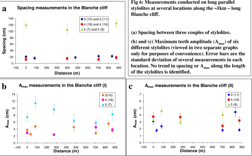
Although d ranges from 0.1 to 2.0 meters when looking at different neighbors, the spacing 265
between any two given stylolites is laterally constant, as seen qualitatively in Fig 1 and as 266
quantitatively measured over ~1km in Fig 6a. For example, d between stylolites 3(10) and 3(11) 267
varies (without any obvious spatial trend) between 15 and 22 cm along 850m of the exposure. 268
The lateral variation of maximum stylolite amplitude (Amax) in the Blanche cliff shows no
269
particular trend, i.e. it does not decrease or increase gradually in any direction (Figs 6b, 6c). For 270
example, Amax of stylolite 3(10) varies between 2.5 and 5.5 cm, which in itself may be
271
significant, but does not vary consistently in any direction (e.g. from the center of the cliff 272
3 4 2 5 6 7 4upper 4lower 1+2 1 0 3 Top 4 “hiding”
3
4
2
5
6
7
4
upper4
lower1+2
1
0
3
Top 4 “hiding”
a
Fig 5: Images showing the Blanche (Ein El-Assad Fm.) section in the northern part of the cliff, where all 65
stylolites were identified and measured.
(a) The section was divided to 9 major units differentiated by major stylolites (in orange). Most of the
measurements were performed in the parts that are marked in white, which are more accessible.
(b) Zoom on rectangle in (a). Stylolites are labeled according to their vertical position within a unit, i.e., 5 (3)
is the third stylolite from the bottom of unit 5.
4 (19) 4 (18) 5 (5) 5 (6) 5 (7) 5 (8) 5 (9) 5 (10) 5 (12) 5 (13) 5 (3) 5 (1) 4 (14) 4 (13) 4 (11) 4 (11a) 4 (12) Unit 5 Unit 4 upper 4 (19) 4 (18) 5 (5) 5 (6) 5 (7) 5 (8) 5 (9) 5 (10) 5 (12) 5 (13) 5 (3) 5 (1) 4 (14) 4 (13) 4 (11) 4 (11a) 4 (12)
Unit
5
Unit
4
upperb
Fig 6: Measurements conducted on long parallel
stylolites at several locations along the ~1km – long
Blanche cliff.
(a) Spacing between three couples of stylolites.
(b) and (c) Maximum teeth amplitude (A
max) of six
different stylolites (viewed in two separate graphs
only for purposes of convenience). Error bars are the
standard deviation of several measurements in each
location. No trend in spacing or A
maxalong the length
of the stylolites is identified.
Amax measurements in the Blanche cliff (I)
0 2 4 6 8 10 12 14 -100 0 100 200 300 400 500 600 700 800 900 Distance (m) Ama x ( c m ) 3(10) 4 (18) 5 (7)
Amax measurements in the Blanche cliff (II)
0 1 2 3 4 5 6 7 -100 0 100 200 300 400 500 600 700 800 900 Distance (m) Ama x ( c m ) 3 (11) 4 (19) 5 (9) Spacing measurements in the Blanche cliff
0 20 40 60 80 100 120 140 -100 0 100 200 300 400 500 600 700 800 900 Distance (m) Sp a c in g ( c m ) 3 (10) and 3 (11) 4 (18) and 4 (19) 5 (7) and 5 (9)
b
c
a
sideways, or from one end to the other). This either suggests that terminations are still far away, 273
or that the observations and conclusions of Mardon (1988) and Stockdale (1922) on isolated 274
seams, showing tapering of seam thickness and teeth amplitude from center to edges, do not 275
apply here. This will be discussed below. 276
277
3.2 Anastomosing stylolite network in Mitzpe Ramon Quarry 278
We focus here on statistics of islands formed by stylolites. The islands vary widely in size, 279
from centimeter to a couple of meters in width and length, yet show robust characteristics: Fig 7a 280
shows the connection angle, θ, between two connecting stylolites, as a function of the distance 281
from their junction, L, as defined in Fig 3. Each data point is the average of all θ(Li) in the
282
exposure and the error bars are the standard deviation, both produced from normal distribution 283
best-fits to each value of L (inset in Fig 7a). Connection angle in the anastomosing stylolite 284
network of the Mitzpe Ramon Quarry is found to be distance dependent. Close to the connection 285
points, i.e. for L<2cm, θ=80º-90º, but this value decreases asymptotically to zero (stylolites 286
become sub-parallel) for larger values of L. This means that stylolites meet at near perpendicular 287
angles (similarly to cracks), but approach parallel planes when far “enough” apart (L>>5cm). 288
Fig 7b shows vertical versus horizontal dimensions (ξ┴ versus ξII), of over 3300 islands
289
analyzed in this site. We identify a robust power-law relation between the height and width of 290
islands: Performing a linear fit in bi-logarithmic space of ξ┴ versus ξII , we obtain
291
(1) 292
with k [m1-α] =0.67 ± 0.01 and α (unitless) = 0.67 ± 0.03 (The reason that both constants are 293
equal is probably by chance). 294
Fig 7:
Results of the statistical analysis performed in Mitzpe Ramon quarry. (a) θ(L) and
(b) Island dimensions, as explained in the text.
The variables are illustrated in Fig 3c. Each data point in (a) is the average of all θ(Li) in the exposure and the error bars are the standard deviation.
The pink line in (b) is a best fit to the correlation between ξ┴ and ξII with both α and k equal 0.67.
b
a
3.3 Stylolite-fracture network in the Umbria–Marche slab, Apennines 296
We view the major stylolites of this slab (Fig 4b) as a long-parallel population (shown to be 297
fractal over 4.5 orders of magnitude (Karcz and Scholz, 2003)), whereas the minor ones are 298
either anastomosing, connected to fractures, or isolated. Many of the fractures have clear 299
interactions with the stylolites, e.g. emanating from-, or connecting between- stylolite tips, or 300
emanating from stylolite teeth. Stylolites and fractures are found to be generally perpendicular to 301
each other, as seen qualitatively in Fig 4b and quantitatively in Fig 8. However, a significant 302
population of fractures that are sub-parallel to the stylolites is also seen in Fig 8. 303
304
Small-scale observations
305
Relations between stylolites and fractures in this network imply that the two types of 306
features are probably related to one another (Fig 9). Stylolites are often connected to each other 307
via fractures (Figs 9a, 9d, and 9f), though regions of anastomosing stylolites are also quite 308
common (Fig 9c). Fractures in this network are either Mode I veins or Mode II shear fractures 309
with some offset. Fractures interpreted as Mode II shear fractures based on geometrical 310
considerations, may exhibit small “pull-apart” features filled with cement (Fig 9a). Many Mode I 311
veins appear at some acute angle to stylolites while others emanate from stylolite teeth (or what 312
seem to be terminations) and are perpendicular to the stylolite mean surface (Fig 9b). Veins 313
connected to stylolites often taper away from the stylolite (e.g. Fig 9b). Similar tapering was also 314
described by Eren (2005). Some fractures simply connect neighboring stylolites (Figs 9a, 9f) 315
while complex connections, such as in Fig 9d, are very common as well. At the scale of 316
observation, some features appear not to be fully physically connected (e.g. Figs 9b, 9d). Perhaps 317
there is connection in 3D that is not seen in the 2D view. Even when the connections are more 318
difficult to observe, such as in Fig 9b, geometry suggests strain-related interactions between the 319
stylolites and fractures. 320
Stylolite
Fracture
Fig
8: Orientations of stylolites and
fractures in the Umbria–Marche slab,
Apennines (analyzed upon map in Fig 4).
Fig 9: Zoom-in on the slab of Fig 4 showing small-scale field-relations between fractures and stylolites and between the stylolites themselves. (a) Mode II fracture with pull-apart structure filled with cement connecting two stylolites. Interpreted strain direction is marked by arrows.
(b) Interconnected stylolite network that seems to be derived from stylolite “cannibalism” (see text for further explanation).
(c) Mode 1 veins sub-parallel to the stylolite teeth and splaying from them. The veins are commonly triangular, with the aperture being largest close to the stylolite surface. stylolite mean direction is changed near a vein (circled region). (d) Complex connection between non-overlapping stylolites by an array of oblique veins.
(e) Veins parallel to stylolite surface mean direction indicating on extension that is in the same direction as
compression (see arrows). This population of fractures parallel to stylolites is statistically common (see Fig 8).
(f) Vein and stylolites closely interacting. We interpret such intimate geometries as indicating on these features to be syn-formational.
Figs 9a, 9b and 9c illustrate possible mechanisms for the formation of the observations in Figs 8a, 8b and 8c, respectively.
1cm
d
1cm
e
1cm
b
1cm
f
1cm
1cm
a
c
Veins parallel to the mean surface of the stylolite are seen in Figs 9e, and are statistically 321
important (Fig 8). Explanations and implications of this observation are suggested in the 322 discussion. 323 324 325
4. Discussion
326We suggest using natural divisions provided by percolation theory, in order to 327
characterize the connectivity of natural stylolite populations. Pervious classification schemes for 328
stylolites and pressure solution addressed roughness, spacing, relation to bedding and seam 329
geometry (Park and Schot, 1968, Alvarez et al., 1978, Powell, 1979, Guzzetta, 1984, Engelder 330
and Marshak, 1985, Railsback, 1993). Although these are very useful quantification approaches 331
for classifying single stylolites, they do not address quantification needs for describing 332
connectivity, as percolation theory offers. 333
Based on the observations and measurements presented above and on the theoretical 334
possibilities for connectivity/percolation of surfaces in a 3-D space (presented in the 335
introduction), we may categorize sedimentary stylolite populations into three 336
connection/percolation geometries (Fig 10): 337
Class I: Isolated stylolite populations - no percolation of stylolites (Fig 10a):
338
These are stylolitic surfaces with clear terminations and no connections to other stylolites 339
or fractures. Stockdale (1922) and Mardon (1988) report finding isolated stylolites and solution 340
seams, respectively, in carbonates. Benedicto and Schultz (2010) investigated isolated tectonic 341
stylolites and the strain associated with them in a ~0.2m-thick limestone layer in a fault-damage 342
zone. Nenna and Aydin (2011) describe isolated tectonic solution seams in a sandstone 343
formation. 344
a) Isolated stylolites (zero connectivity)
b) Long bedding-parallel stylolites
(2D connectivity)
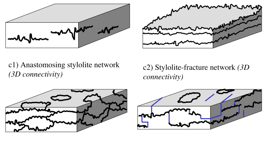
c1) Anastomosing stylolite network
(3D connectivity)
c2) Stylolite-fracture network (3D
connectivity)
Fig 10. Connectivity-based classification of sedimentary stylolite populations: (a) Isolated stylolites; (b)
Long bedding-parallel stylolite population; and (c) Interconnected-netwo rk stylolite population, further
divided into (c1) anastomosing networks of stylolites and (c2) inter c onnec ted networks of stylolites and
fractures (fractures appear in blue).
Class II: Long, bedding- parallel, stylolite populations - 2D percolation of stylolites
345
(Fig 10b):
346
In this group stylolites are virtually infinite bedding-parallel rough surfaces that do not 347
connect since they are parallel. These stylolitic surfaces have roughness with amplitude smaller 348
than the spacing between them, so they also don‟t overlap. Tracing these surfaces connects the 349
rock body from side-to side in 2 dimensions, sub-parallel to bedding, but not in the 3rd
350
dimension, perpendicular to the surfaces and to bedding. Long bedding-parallel stylolites (or 351
solution seams) were seldom described in the literature (Park and Schot, 1968, Safaricz, 2002, 352
Safaricz and Davison, 2005). 353
Class III: Interconnected stylolite networks- 3D connectivity (Fig 10c):
354
Here stylolite surfaces are connected to one another by anastomosing or via fractures and 355
veins. One can trace along these surfaces, following a "stylolite pathway", from any side of the 356
rock to any other side, since surfaces percolate in 3 dimensions. Interconnected stylolite 357
networks can be further divided into anastomosing stylolite networks and stylolite-fracture 358
networks. Interconnected stylolites were reported in several references (Mardon, 1988, Rye and
359
Bradbury, 1988, Peacock and Sanderson, 1995, Smith, 2000, Safaricz, 2002, Eren, 2005). 360
361
The stylolite populations in our investigated sites either clearly fall into one of the 3 end-362
member connectivity classes, or present a combination of more than one class. Long, parallel 363
stylolite populations (Fig 10b) and Interconnected networks (Fig 10c) are both commonly
364
observed in field locations, as seen in the Supplementary Material (sites # 4-16). Isolated 365
stylolites (Fig 10a) were not observed as a separate class in our field sites. Several stylolites in
366
the stylolite-fracture network in the Umbria-Marche slab seem to terminate in our observed 2D 367
plane, but possibly they are connected in 3D. The last site reported in the Supplementary (#17) is 368
the only location with isolated features (often forming networks) and for this reason we included 369
it, although the features are solution seams and not stylolites. Based on our fieldwork and on 370
literature, it appears that isolated stylolites are uncommon, though isolated pressure solution 371
seams are not rare (Mardon, 1988, Nenna and Aydin, 2011). In terms of evolution, isolated 372
stylolites, the non-percolating structure, may only be an intermediate stage in the evolution 373
process of percolating stylolites (which might explain their scarcity), as discussed in the next 374
sub-section. But in terms of topology isolated stylolites are one of the 3 topological possibilities 375
for connectivity of stylolitic planes, so for the sake of characterizing morphology we propose to 376
consider them as a separate class – the class of “no connectivity”. 377
The Supplementary Material presents 14 additional field sites with large-scale stylolite 378
exposures. Out of these, 3 have long-parallel stylolite populations, 6 have interconnected 379
networks of both sub-groups, while 4 sites present a combination of end-member connectivities. 380
Combinations were mostly of long parallel stylolites with anastomosing network in between. 381
382
4.1 Conceptual model for formation of observed stylolite populations
383
Here we present a conceptual model of stylolite population formation to facilitate an 384
understanding of strain accommodation by stylolite populations. We review briefly the formation 385
of isolated and long-parallel stylolites, as it is discussed and modeled in detail in Aharonov and 386
Katsman (2009) and Laronne Ben-Itzhak et al. (2012), respectively. Table 2 summarizes how our 387
field measurements support suggested formation mechanisms for each of the different 388 populations. 389 390 4.1.1. Isolated stylolites: 391
The amount of discussion of the formation of this type of population (Fletcher and Pollard, 392
1981, Mardon, 1988, Aharonov and Katsman, 2009) is inversely proportional to their prevalence. 393
These constitute Localized Volume Reduction (LVR) defects, as defined by Katsman and 394
Aharonov (2005), and Katsman et al. (2006a, b). Field observations of these features show 395
Table 2: Summary Table: suggested mechanisms for evolution of the various stylolite populations and the type of measurements that support each mechanism
Population Type Suggested Mechanisms Measurements How Measurement Supports Mechanism Isolated stylolites;
zero connectivity Initiation from seed, continuing dissolution and elongation due to both stress and composition (clay?)
Amax versus
Length If more developed (large Amax) in center and less
towards edges, may indicate in-plane-propagation. Long-Parallel stylolites; 2D connectivity Initiation and continuation of roughening and dissolution on an existing surface (of higher clay content?)
-Amax versus Length -Spacing versus length - Surface roughness
Constant Amax, constant
spacing between stylolite pairs along the surface, and upper cutoff to self-affinity suggest roughening of an existing surface. Anastomosing stylolite networks; 3D connectivity Cannibalism of bedding-parallel stylolites AND/OR Joining of isolated stylolites -Intersection angle -Island dimensions Finding of intersection angle of 35º-45º may support formation by joining of isolated stylolites; If angle is random – supports cannibalism. If around 90º, supports connection by fractures Understanding how to use the statistical characteristics of Islands to estimate the amount of dissolution, depends on the physics of network formation (discussed in the text) Stylolite-fracture
network; 3D connectivity
Increased shear-stress near stylolite tips AND/OR
Connection of stylolite tips with Mode I cracks
-Directions (angles of stylolites and of fractures) -Small-scale field relations Pull-aparts adjacent to stylolite tips
Mode I cracks seem to attract stylolite tips.
References which appear in Table 1
1. Safaricz, M., Pressure solution in chalk. 2002, Royal Holloway University of London.
2. Arzani, N., Stylolite networks in dolomitized limestones and their control on
polished decorative stones: a case study from the Upper Cretaceous Khur quarries, central Iran. JGeope, 2011. 1(2): p. 25-37.
3. Losonsky, G., Burial depth and lithofacies control of stylolite development in
the Mississippian Salem Limestone, Illinois Basin. 1992, University of
Cincinnati.
4. Mardon, D., Localized pressure solution and the formation of discrete solution
geometrical characteristics similar to cracks: (1) their amplitude and thickness taper towards their 396
edges and (2) their length increases with increasing seam thickness and amplitude (Stockdale, 397
1922, Mardon, 1988). Such features may develop self-similarly from an initial seed defect, 398
provided that it grows laterally sub-parallel to its plane and experiences continued dissolution on 399
its flanks (e.g. Fletcher and Pollard (1981)). Aharonov and Katsman (2009) show that 400
development of isolated stylolites can be explained by a feedback that arises when both clay 401
(present in the rock at some small fraction, and in initially higher content in seed defects) and 402
pressure solution enhance the dissolution process. Nenna and Aydin (2011) suggest that they 403
elongate and thicken due to the presence of asperities. 404
405
4.1.2. Long, parallel stylolite populations: The formation of this abundant, yet rarely
406
acknowledged, population type was indirectly studied before: the group of Ebner and Kohen 407
(Renard et al., 2004, Schmittbuhl et al., 2004, Koehn et al., 2007, Ebner et al., 2009a, Ebner et 408
al., 2009b) studied roughening from a prescribed surface. We suggest long parallel stylolites 409
form on planes where dissolution is for some reason enhanced, possibly due to initial chemical 410
heterogeneity (e.g. higher initial content of clay or other dissolution enhancing chemical 411
heterogeneity). In sedimentary stylolites such planes are most commonly bedding planes. Our 412
conceptual model suggests that long parallel stylolites do not evolve by lateral elongation of 413
isolated stylolites, but instead by dissolution-roughening on a preexisting plane, as suggested in 414
Laronne Ben-Itzhak et al. (2012). This is implied by the constant roughness amplitude we 415
measured along almost 1km (Fig 6), which does not follow the observed „parabolic‟ self-similar 416
profile of dissolution along isolated stylolites (Stockdale, 1922, Mardon, 1988). In 417
supplementary B we present a simple calculation that shows that the amount of dissolution on the 418
Blanche stylolites would have been far larger than measured if they evolved by elongation from a 419
seed rather than roughening of an existing surface. Spatially constant amplitude, as observed 420
here, is consistent with a process invariant under translation along the stylolite. It is easiest to 421
explain the observed long parallel stylolites as forming by localized dissolution on an initially 422
flat plane (most often a bedding plane), that progressively roughens with time, driven by 423
competing effects of stress, diffusion and noise (Koehn et al., 2012, Laronne Ben-Itzhak et al., 424
2012, Rolland et al., 2012). The dissolution creates a self-affine surface, following a scaling law 425
between the out-of-plane root mean square width, w(l), and the in-plane length, l, at which this 426
width is defined: w(l)~lH, with a Hurst exponent H~0.65, and with an upper cutoff for
self-427
affinity that grows with increasing amount of dissolution (Renard et al., 2004, Schmittbuhl et al., 428
2004, Koehn et al., 2007, Ebner et al., 2009a, Laronne Ben-Itzhak et al., 2012). 429
430
4.1.3. Interconnected stylolite networks
431
This is again a very common type of population (sites # 2-6, 8-10, 13-16), which has not 432
received much previous attention, and its formation has rarely been discussed. Based on our 433
field observations, we propose that interconnected networks can form by one of three 434
mechanisms or through a combination thereof. The three mechanisms are: (i) Connection of tips 435
of isolated stylolites via dissolution or Mode II fractures; (ii) Connection of stylolite tips with
436
Mode I cracks (iii) Connection of long parallel stylolites; (Figs 11a, 11b and 11c, respectively,
437
linked to the examples in Figs 9a, 9b and 9c, respectively). In (i) and (ii) a population of non-438
touching surfaces of type (a) in Fig 10, connects as it evolves to finally create a percolating 439
structure. In (iii) initially sub-parallel planes (type b in Fig 10) roughen enough with time to 440
connect in the bedding perpendicular direction. 441
442
(i) Connection of tips of isolated stylolites: This may occur when two neighboring LVRs
443
start to “feel” the normal and shear stress field of each other, and interact (e.g. Fueten and Robin 444
(1992), Zhou and Aydin (2010)). Fig 11a shows a cartoon of normal and shear stresses that arise 445
from dissolution on two horizontally over-lapping stylolites at a vertical distance d from each 446
other, and the expected evolution due to these two stress fields, the normal and the shear: 447
1. Increased normal stress leading to increased dissolution (Fig 11a1): increased 448
compressive normal stress arises near the tip of each stylolite, with a maximum value achieved at 449
35º-45º from the mean stylolite plane, as indicated by the “heart-shaped” blue region, following 450
stress calculation for LVR. In case of uniform dissolution along the stylolite one can use the fact 451
that such an LVR defect induces a stress like an “edge dislocation” (Katsman et al., 2006a), and 452
use the calculated stress fields (Landau and Lifshitz (1986), p. 114) to conclude that maximum 453
compressive stress is induced by the tip at 45º. In case of elliptical dissolution the maximum is 454
found numerically at 35º (Katsman (2010a)). If spaced at a close enough vertical distance, d, 455
stylolites are expected to induce pressure solution in the compressive stress-enhanced region 456
between them, and thus connect by dissolution. Similar stylolite connections, via curving tips, 457
were seen by Mardon (1988) in a partially connected network of solution seams. In the 458
anastomosing networks observed at the Mitzpe Ramon site, curving planes are abundant: at 459
scales larger than ~2cm, angles between connecting stylolites are small (approach zero - become 460
parallel), while at smaller scales they are ~80º (Figure 8a). It is important to note that we find no 461
peak in the probability function of angles around the expected value of 35º-45º. This suggests 462
that there might be another process controlling stylolitic connections, possibly formation of shear 463
or Mode-I fractures that link adjacent stylolites, or connection by „cannibalism‟ of long parallel 464
stylolites, as detailed below. 465
2. Increased shear strain region leading to connection of stylolites by a shear fracture 466
(Fig 11a2): In addition to compressive stress, any LVR defect - like the analogous “edge 467
dislocation” - is calculated theoretically to induce shear stresses near its tip in the plane normal to 468
it (Landau and Lifshitz (1986), p. 114). The stresses are linearly proportional to the amount of 469
volume removal (in this case amount of dissolution), and decay as 1/distance from the tip. The 470
fact that shear stress is induced by a stylolite tip can also be understood intuitively: Two 471
offsetting stylolites may be viewed as analogs to offset mid-ocean ridges, but with an opposite 472
sign. While mid-ocean ridges are spreading centers that create rock, stylolites are converging 473
Fig 11:
Cartoon showing several possible
mechanisms for the formation of
interconnected stylolite networks from
time t1 to t2.
(a) Connection of isolated stylolites.
Increased normal stress (in
blue-heart-shaped-regions) enhances dissolution and
may change propagation direction (a1),
while increased shear strain may cause
fracturing (a2). This depends on the
mechanical properties of the rock at that
time. A and d (a2) control weather there
will be connection by linkage or
fracturing. Blue arrows (a2) show stress
direction.
(b) Connection of long-parallel stylolites
by their dissolution and roughening
(“cannibalism” of closely spaced
long-parallel stylolites).
(c) Connection of stylolites via mode I
fractures, emanating from stylolite teeth.
Such fractures can connect stylolites
according to both models (a) and (b)
(connection of single stylolites or
continued dissolution of parallel
stylolites). Tips of an adjacent stylolite
may curve towards such vein, which
induces extensive strain. This scenario fits
with stylolite localizing via high
A
d
(b)
Connection of
long-parallel stylolites
(a1)
connection of
isolated stylolites by
increased dissolution
(a2)
connection of
isolated stylolites by
mode II fractures
(c)
Connection by
mode I fractures
t1
t2
t1
t2
t1
t2
t1
t2
centers that destroy/dissolve rock (Peacock and Sanderson, 1995). When spreading/converging 474
centers are positioned at an offset, they produce shear strain between them, proportional to the 475
amount of rock created/destroyed. When the shear stress exceeds the material strength, a transfer 476
fault will form and connect the two stylolites, similar to transform faults that connect offsetting 477
mid-ocean ridges. “Pull-aparts” are common features in these transfer/transform faults, as seen in 478
Fig 9a and discussed by Peacock and Sanderson (1995). 479
Two competing processes thus occur between “properly” oriented offset neighboring 480
growing stylolites: shear fracturing between them due to increased shear stress, and dissolution 481
due to increased normal stress. The two types of network stylolite populations (interconnected 482
stylolites and stylolites and fractures) differ in the dominant mechanism: when shear fracturing 483
dominates, stylolites and fractures will form; when dissolution dominates, interconnected 484
stylolites form. Whether one mechanism prevails over the other may be associated with the 485
hydrological state of the rock at the time of deformation: dissolution requires water at the grain 486
contacts and a fluid path for solute to migrate or diffuse through. Alternatively, the control on 487
which mechanism dominates may be related to the mechanical strength of the rock at the 488
overlapping region, which in turn is controlled, inter alia, by rock composition, porosity and 489
local defects. 490
491
(ii) Connection of stylolite tips with Mode I cracks (Fig 11b): The 2nd process by which
492
isolated or planner stylolites may form networks, involves interaction between a stylolite and a 493
Mode I vein. Mode I veins are often associated with stylolites (Rye and Bradbury, 1988, Smith, 494
2000, Eren, 2005) and several mechanisms have been suggested to explain their common 495
appearance perpendicular to compression, i.e. at 90 degrees to stylolites (e.g. Fig 9b, 9d): 496
concentrated compressive stress at tips of stylolite teeth (Zhou and Aydin, 2010); high fluid pore 497
pressure within stylolites (Eren, 2005); and extensional stress in the mid-section of stylolites 498
(Katsman, 2010). Regardless of its formation mechanism, a vein will impact stress-enhanced 499
dissolution in its vicinity, both by enhancing fluid-mediated solute transport (via flow and/or 500
diffusion), and by perturbing the stress field (Renard et al., 2000a, Renard et al., 2000b). 501
According to the stress fields (Landau and Lifshitz (1986), p. 114) both opening and Mode II 502
fractures are expected at certain regions around a stylolite tip, but 180o between stylolites and
503
veins is not expected from the stress fields, since compactive features such as stylolites induce 504
compressive stress perpendicular to their plane (Fletcher and Pollard, 1981, Katsman et al., 505
2006a) while veins induce exactly the opposite- extension perpendicular to their opening 506
direction. 507
Stress fields alone may thus not suffice to explain all vein -stylolite attraction, e.g. such as 508
the interaction in Fig 9b. It is possible to attribute some of the attraction to connectivity and 509
availability of fluid in veins, that allows fluid enhanced dissolution to dominate the location and 510
direction of stylolite propagation (e.g. (Renard et al., 2000a, Renard et al., 2000b, Aharonov and 511
Katsman, 2009). This suggests that the connectivity of stylolites and their ability to transfer 512
solute in fluid may dominate, at least in some cases, their growth and propagation. The fact that 513
fluid flow pathways, specifically cracks, enhance pressure solution rates has been observed also 514
in experiments (Gratier et al., 2009, Croize et al., 2010). 515
516
(iii) Connection of long parallel stylolites is the third possibility for formation of
517
interconnected stylolite networks (Fig 11c). Continued dissolution and roughening of essentially 518
2D stylolites can result in two stylolites merging in the 3rd, bedding perpendicular, direction, at 519
least along a limited segment (e.g. Fig 9c). Islands in this case are formed as leftover untouched 520
regions between coalescing initially self-affine surfaces. In a somewhat similar physical picture 521
(fracture fronts), where self-affine surfaces „eat each other‟ (cannibalism) and by this merge in 522
places, it was shown that island-scaling is related to the Hurst exponent of the merging surfaces 523
(Maloy et al., 2005, Maloy et al., 2006, Tallakstad et al., 2011). Comparison between the scaling 524
of islands and the Hurst exponent of the stylolites may aid in constraining the physical process 525
for network growth, and in understanding why the power-law relating out-of-plane and in-plane 526
dimensions of islands is characterized by an exponent 0.67, similar to the Hurst exponent of
527
single stylolites, as reported e.g. by Ebner et al. (2009a); Koehn et al. (2007); Laronne Ben-528
Itzhak et al. (2012); and Rolland et al. (2012). 529
Connection angles could be used to distinguish whether connectivity occurred by isolated 530
stylolites meeting at tips or via long stylolites “cannibalizing” each other: If stylolites are 531
infinite- long- roughening- planes cannibalizing each other, connection angles are expected to be 532
random, since the geometry of a stylolite at any given point (away from its tip) can be assumed 533
to be independent of the geometry of the stylolites above and below it at the merging point. 534
Alternatively, if stylolites connect at tips, connection angles are expected to be ~35º-45º if 535
connection is by dissolution (Katsman, 2010), or ~90˚ if by a series of micro-fractures or by 536
larger-scale fractures (Kaduri, 2013). In our case-studies connections are close to 90º at small 537
scales, but present a large variability around this value (inset in Fig 7a), which suggests that 538
micro-fractures are probably involved yet that both mechanisms are plausible. 539
540
4.2 Strain accommodated by stylolite networks
541
The dissolution on stylolites introduces an irreversible volume loss in the direction 542
perpendicular to the stylolite, which produces a compactive strain. In the section below we 543
attempt to determine the amount of strain accommodated by the three types of stylolite 544
connectivity classes. The large-scale connections between stylolites and veins are shown to be 545
important in allowing strain accommodation. 546
547
Isolated stylolites populations
548
Isolated stylolites can accommodate a finite and small amount of dissolution before 549
connecting by dissolution or by shear fractures. Thus, although isolated stylolites may be 550


![[PDF] Cours XML : introduction aux DTD et schemas - Cours xml](data:image/gif;base64,R0lGODlhAQABAIAAAP///wAAACH5BAEAAAAALAAAAAABAAEAAAICRAEAOw==)