HAL Id: hal-03000844
https://hal.archives-ouvertes.fr/hal-03000844
Submitted on 12 Nov 2020
HAL is a multi-disciplinary open access
archive for the deposit and dissemination of
sci-entific research documents, whether they are
pub-lished or not. The documents may come from
teaching and research institutions in France or
abroad, or from public or private research centers.
L’archive ouverte pluridisciplinaire HAL, est
destinée au dépôt et à la diffusion de documents
scientifiques de niveau recherche, publiés ou non,
émanant des établissements d’enseignement et de
recherche français ou étrangers, des laboratoires
publics ou privés.
Structural changes of Nd- and Ce-doped ammonium
diuranate microspheres during the conversion to
U1–yLnyO2
±x
Christian Schreinemachers, Gregory Leinders, Renaud Podor, Joseph Lautru,
Nicolas Clavier, Giuseppe Modolo, Marc Verwerft, Koen Binnemans, Thomas
Cardinaels
To cite this version:
Christian Schreinemachers, Gregory Leinders, Renaud Podor, Joseph Lautru, Nicolas Clavier,
et al..
Structural changes of Nd- and Ce-doped ammonium diuranate microspheres during the
conversion to U1–yLnyO2
±x.
Journal of Nuclear Materials, Elsevier, 2020, 542, pp.152454.
Graphical Abstract
Structural changes of Nd- and Ce-doped ammonium diuranate microspheres during the conversion to U1−yLnyO2±x Christian Schreinemachers, Gregory Leinders, Renaud Podor, Joseph Lautru, Nicolas Clavier, Giuseppe Modolo, Marc Ver-werft, Koen Binnemans, Thomas Cardinaels
α-U3O8 10 mol% Nd-doped α-U3O8 10 mol% Ce-doped α-U3O8 10 mol% Ce-doped α-U3O8 mnorm. (TG-DSC) rnorm. (HT-SEM) inert N2:H2 (HT-SEM) Ar:H2 (TG-DSC) mnorm. (TG-DSC) rnorm. (HT-SEM)
calcination in air, Tmax ≈ 900 °C XRD after calcination reduction in H2, Tmax ≈ 1100 °C
un-doped ADU 10 mol% Nd-doped ADU 10 mol% Ce-doped ADU 10 mol% Ce-doped ADU Ce III precursor Ce IV precursor
Highlights
Structural changes of Nd- and Ce-doped ammonium diuranate microspheres during the conversion to U1−yLnyO2±x Christian Schreinemachers, Gregory Leinders, Renaud Podor, Joseph Lautru, Nicolas Clavier, Giuseppe Modolo, Marc Ver-werft, Koen Binnemans, Thomas Cardinaels
• Crack formation during calcination in air observed, cracks heal and spheres shrink • Fractures and shrinkage differs significantly for CeIVcompared to CeIIIprecursor
• Macroscopic behaviour related to release of volatile decomposition products • Less rapid reduction of α-U3O8matrix to UO2±xfor CeIVprecursor (Ar:H2, 700 °C) • Shrinkage mainly attributed to sintering effects and less to phase transitions
Structural changes of Nd- and Ce-doped ammonium diuranate microspheres during the
conversion to U
1−yLn
yO
2±xChristian Schreinemachersa,b,∗, Gregory Leindersa, Renaud Podorc, Joseph Lautruc, Nicolas Clavierc, Giuseppe Modolod, Marc Verwerfta, Koen Binnemansb, Thomas Cardinaelsa,b
aBelgian Nuclear Research Centre (SCK CEN), Institute for Nuclear Materials Science, Boeretang 200, B-2400 Mol, Belgium
bKU Leuven, Department of Chemistry, Celestijnenlaan 200F, P.O. Box 2404, B-3001 Heverlee, Belgium
cICSM, Univ Montpellier, CEA, CNRS, ENSCM, Bagnols-sur-C`eze, France
dForschungszentrum J¨ulich GmbH, Institute of Energy and Climate Research, IEK-6: Nuclear Waste Management and Reactor Safety, 52425 J¨ulich,
Germany
Abstract
The structural changes of ammonium diuranate (ADU) microspheres, prepared by the sol-gel route via internal gelation, were investigated during thermal treatments in oxidative and reducing conditions. In particular, in-situ simultaneous thermogravi-metric analyses and in-situ high-temperature scanning electron microscopy investigations were carried out on un-doped ADU microspheres, and ADU microspheres doped with 10 mol% neodymium or 10 mol% cerium. Calcination in air caused the sur-face of the particles to crack, but with increasing temperature up to 900 °C some healing, and additionally, shrinkage occurred. The extent of the fractures and the amount of shrinkage was, however, significantly more pronounced in a particle prepared with a tetravalent Ce precursor, as compared to particles prepared with a trivalent Nd or Ce precursor. The macroscopic behaviour could be related to the release of volatile decomposition products and the calcined compositions were identified as (Ln-doped) α-U3O8by X-ray powder diffraction. During thermal treatment in reducing conditions a transition from a (Ln-doped) α-U3O8phase to a (Ln-doped) UO2±xphase was observed. After exposure to a hydrogen containing gas mixture, this transition occurred rapidly in un-doped particles, and in particles prepared with trivalent Nd or Ce dopant precursors at 700 °C. Despite the fast reduction reaction, severe fractures appeared in the particles above temperatures of 850 °C, indicating that such behaviour is mainly attributed to sintering effects and less to the phase transition. In contrast, a more delayed reduction reaction was observed in particles prepared with a tetravalent dopant precursor and the described effects appeared less severe. Keywords: nuclear fuel fabrication, co-conversion, sol-gel, internal gelation, GenIV
1. Introduction
In the context of minor actinide (MA) recycling of spent nuclear fuel, research on alternatives to the conventional powder processing for the fabrication of MA-containing transmutation fuel is currently carried out. To avoid handling of fine powders and to facilitate automation for the production of nuclear fuel particles, sol-gel processes have been explored for more than six decades [1–6]. The sol-gel routes via internal- and external gelation are common sol-gel methods, which are based on 5
the precipitation of a metal nitrate solution by ammonia into a metal hydroxide. The major difference between both methods is the source of ammonia. During the external gelation, the sol is dropped via a layer of gaseous ammonia into ammonia solution and the precipitation is triggered by a NH3mass transfer into the sol droplet [7]. It occurs while the droplet is falling,
∗Corresponding author
resulting in a spherical particle. In the internal gelation (IG), a heat transfer causes reactants in the sol to get protonated and decompose thermally to ammonia directly within sol droplets [8]. The resulting pH increase causes the solidification. 10
The spherically shaped precipitate is thermally treated and can afterwards directly be used as particle fuel [9] or compressed into the commonly used fuel pellets [10]. The IG process offers a dust-free fabrication route to convert mixtures of different metal cations into a homogeneous precipitate and was used to prepare MOX particles [11] and U/Pu nitride particles [12]. Moreover, it might be a promising strategy to produce americium-containing transmutation fuel [13], as envisaged by the scientific community to close the nuclear fuel cycle.
15
The IG process was applied to fabricate Nd-doped UO2±x particles with up to 43 mol% Nd [14], using neodymium as simulant for the trivalent MA americium. It was optimised in terms of automation and its suitability to prepare Ce-doped UO2±xmicrospheres was investigated using CeIIIand CeIV dopant precursors to simulate plutonium [15]. Microspheres con-taining up to 30 mol% Ln were fabricated using NdIIIand CeIII, while CeIV was suitable to prepare microspheres with up to
10 mol% dopant, using the chosen gelation parameters. The dopant was successfully incorporated into the 3UO3·2NH3·4H2O 20
matrix [16] of the dried gels, which was converted into U1−yLnyO2±xsolid solutions by a calcination in air at 900 °C for one hour and a subsequent sintering in reducing atmosphere at 1600 °C for 10 h. Sintering under reducing conditions resulted in broken particles for the compositions prepared with the CeIII precursor and higher dopant contents (≥ 15 mol%), while
compositions prepared with CeIVexhibited cracks on the surface [15]. The thermal decomposition of un-doped ADU
parti-cles during the calcination in air was investigated by a combination of thermogravimetric analyses (TGA), thermogravimetric 25
differential scanning calorimetry (TG-DSC), evolved gas analysis mass spectrometry (EGA-MS) and in-situ high-temperature X-ray powder diffraction (HT-XRD) [16]. However, no information on the dopants’ influence on the thermal decomposition of Ln-doped ADU particles prepared by IG are available in literature, which was the motivation to investigate the thermal treatment of the gelled particles during their conversion into U1−yLnyO2±x. Moreover, we want to study the particle behaviour during the sintering under reducing conditions.
30
Within this work, the structural changes of un-doped ADU particles, and ADU particles doped with about 10 mol% Nd or Ce were analysed during the conversion to (Ln-doped) UO2±x. For the Ce-doped material, particles prepared with a trivalent and a tetravalent dopant precursor were selected. The thermal treatment was performed using simultaneous thermogravimetric analyses (STA) to investigate the decomposition and phase transitions occurring during a calcination in air (Tmax= 900 °C, 1 h) and a sintering in reducing atmosphere (Tmax = 1000 °C, 2 h). Moreover, in-situ high-temperature scanning electron 35
microscopy (HT-SEM) investigations were carried out, simulating also both thermal treatment steps.
2. Experimental
2.1. Fabrication of particles
The sample material studied within this work was fabricated by the sol-gel route via internal gelation (IG), using acid-deficient uranyl nitrate (ADUN) solution as uranium precursor. The preparation of the ADUN solution (c(U)= 2.6 mol L−1, 40
pH= 1.7, ρ = 1.85 g cm−3, c(NO3–)
c(U) = 1.56) and un-doped ADU gels is described elsewhere [16]. A similar methodology was applied to prepare Nd- and Ce-doped ADU gels with dopant contents up to 30 mol%, using the hexahydrate nitrates of the trivalent lanthanides and diammonium nitrate of cerium(IV) as dopant precursors. The fabrication is described in detail in our previous study [15]. In both studies, urea and hexamethylenetetramine (HMTA) served as gelation agents during the IG
process, the gelation agent amount is expressed as ratio (R) of the molar amounts of the gelation agents to the molar amounts 45
of the metals in the sol. The syntheses of all compositions, independent on the dopant, its content and its oxidation state, were carried out with a molar metal concentration of c(M)= 1.3 mol L−1and R= 1.2 for both gelation agents. Gelation took place in silicone oil (T = 90 °C) and the obtained particles were washed thrice with petroleum benzine, aged for 24 h in ammonia solution (w(NH3)= 12.5 wt%) and washed twice with ammonia solution (w(NH3)= 12.5 wt%). The un-doped particles and compositions containing about 10 mol% dopant, prepared with NdIII, CeIIIand CeIV, were investigated within this study.
50
2.2. Thermogravimetric differential scanning calorimetry
TG-DSC analyses were performed using a NETZSCH STA 449 F1 Jupiter thermobalance, having an absolute uncertainty on mass readout including drift and noise of ±0.03 mg (2σ). The measurements were carried out in Pt/Rh crucibles with heating rates of 10 °C min−1and sample masses of about 20 mg. The particles were ground in a mortar prior to the analyses.
The set-up was evacuated to ≤ 0.63 mbar, then synthetic air was introduced into the furnace and a measurement was carried 55
out purging the system with 80 mL min−1of synthetic air and the balance compartment with 20 mL min−1of argon as protective gas. After an isothermal equilibration plateau at 40 °C (30 min), the calcination in synthetic air was simulated using a heating rate of 10 °C min−1 and a holding time of one hour at 900 °C. Afterwards, it was cooled to 40 °C (10 °C min−1), followed by an isothermal segment at 40 °C (60 min) in which the atmosphere was changed from synthetic air to Ar. To simulate the sintering in reducing atmosphere, the samples were heated up to 700 °C (10 °C min−1) and during an isothermal segment of 60
60 min at 700 °C, the gas atmosphere was changed to Ar:H2(96:4). The temperature was held for about 30 min before it was further heated to 1000 °C at 10 °C min−1. The temperature was not further increased due to experimental restrictions. An isotherm of 2.5 h was maintained at 1000 °C and 30 min prior to its end, the atmosphere was switched back to Ar. Then, the samples were cooled down to 40 °C (10 °C min−1) and a final isothermal equilibration plateau was maintained for one hour. All gases had a purity of 99.9992 % and originated from AIR PRODUCTS SA. Flow rates of 80 mL min−1were used. The 65
applied temperature program is visually summarised in figure 2a.
The sample mass at the end of the initial equilibration plateau was considered as initial in-situ mass. The tare mass of the crucible, as well as the mass of the crucible containing the sample was measured prior to and after the TG-DSC analysis (Mettler-Toledo AT201), having an uncertainty of ±0.04 mg (2σ). The ex-situ masses were used to calculate absolute masses and quantify mass losses occurred during the evacuation of the set-up, since the latter are not logged by the device.
70
2.3. In-situ high-temperature scanning electron microscopy
The HT-SEM investigations were carried out using a FEI Quanta 200 ESEM FEG environmental scanning electron micro-scope, equipped with a FEI HT 1400 furnace. Measurements were performed in a custom made crucible with an integrated thermocouple. The sample is located directly on the thermocouples’ head, allowing precise temperature measurements. De-tails of the set-up were published by Podor et al. [17].
75
The sample itself was prepared as follows: a single microsphere was isolated and stricken onto a high temperature embed-ding ceramic paste (Durapot type from Final Materials). This paste does not react chemically with the microspheres, even at high temperature. The microsphere was positioned in order to remain stable in a hole during the entire heat treatment while minimising the volume of the total montage. The montage was positioned on the head of the thermocouple, and operating conditions were adjusted in order to obtain the best balance between reactivity, sample sensitivity to the electron beam and 80
image quality. Accelerating voltage was fixed to 20 kV, beam current was adjusted to approximately 0.1 nA and working distance was 20 mm. Imaging conditions were managed by adjusting the bias of the heat shield and contrast, brightness and polarisation of the Gaseous Secondary Electron Detector (GSED) [18].
The thermal treatment during the HT-SEM analyses varied from the one applied in the TG-DSC measurements. Instead of argon, nitrogen was used as inert gas, while a reducing atmosphere was maintained by a N2:H2mixture (95:5). Moreover, 85
the chamber of the device was once filled with the desired atmosphere and no dynamic flushing was carried out. During atmosphere changes, a series of 8 purges with pressures ≤ 5 mbar was performed. The temperature profile was comparable to the one of the TG-DSC analyses. Heating rates of 10 °C min−1were used as well, with one exception. The heating to 700 °C within the 2nd step, prior to the introduction of a reducing atmosphere, was performed with a heating rate of 30 °C min−1, N2:H2 was introduced immediately after reaching 700 °C and the heating was directly continued afterwards. Moreover, a 90
maximum temperature of 1100 °C was applied during the sintering in reducing atmosphere. No active cooling was employed for the cooling processes and the reducing conditions were maintained during the cooling of the last treatment step. During the progress of the temperature profile, images were recorded using different magnifications.
Two distinct image processing strategies were developed to determine the volumetric sample variations from the low magnification images. (1) For the un-doped material, as low magnification images recorded did not allow observing the 95
complete microsphere, several features of the sample surface were tracked automatically along the complete image series using the Tracking plugin implemented in the Fiji software package (Version 1.52p) [19]. An average value of the distances from these invariant points was calculated for each image all along the image series. Thus they were correlated to the diameter by several comparison points recorded during the experiment. (2) For the three other image series, very low magnification images were recorded allowing to see the whole microsphere during the heat treatment. Thus, after image segmentation using 100
the Weka Training Segmentation implemented in the Fiji software, the microsphere diameters were automatically calculated for each image of the image series. The background of the images presented in this study was stripped using the GNU Image Manipulation Program(GIMP, Version 2.8.18).
2.4. X-ray powder diffraction
The intermediates after a calcination in air were analysed by X-ray powder diffraction (XRD). A PANanalytical X’PertPro 105
diffractometer, utilising a Bragg–Brentano parafocusing geometry in a θ-θ configuration was used. The device is equipped with a copper LFF X-ray tube as radiation source. The incident beam path was foreseen with a combination of a fixed divergence slit, 0.02 rad soller slits and a copper beam mask. A nickel filter was introduced into the diffracted beam path. Detection was done with a position-sensitive detector (PANalytical X’Celerator). Zero point calibration was performed on a sintered, high purity silicon disc, while a sintered alumina disc (NIST Standard Reference Material 1976b) was used for validations. The 110
instrument bias was assessed by lattice parameter refinement of silicon and was found to be smaller than 2 × 10⁵relative (2σ). The calcination of the samples prior to the measurements was carried out in Al2O3 crucibles, using a heating rate of 1.5 °C min−1and an isotherm of one hour at 900 °C (Nabertherm, LT 9113/P330). Afterwards, the furnace was cooled to a temperature of 150 °C with a rate of 10 °C min−1and the crucibles were stored in a desiccator to cool to room temperature. XRD samples were prepared by mixing one particle with ethanol in a mortar. The material was ground and the resulting 115
suspension dropped onto a zero background silicon single crystal holder. After the ethanol evaporated, diffractograms were recorded in the range from 20° to 143° 2θ, using a step size of 0.017° 2θ.
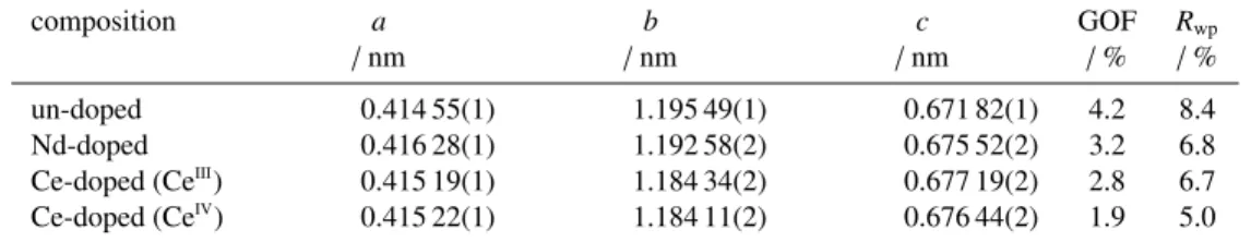
Table 1: Lattice parameters a, b, and c, determined for the orthorhombic (Ln-doped) α-U3O8phase present in the particles after a calcination in air at 900 °C
for 1 h, as well as the goodness of fit (GOF) and weighted-profile R-factor (Rwp) of the refinements.
composition a b c GOF Rwp
/ nm / nm / nm / % / %
un-doped 0.414 55(1) 1.195 49(1) 0.671 82(1) 4.2 8.4 Nd-doped 0.416 28(1) 1.192 58(2) 0.675 52(2) 3.2 6.8 Ce-doped (CeIII
) 0.415 19(1) 1.184 34(2) 0.677 19(2) 2.8 6.7 Ce-doped (CeIV) 0.415 22(1) 1.184 11(2) 0.676 44(2) 1.9 5.0
Lattice parameters were determined using the Pawley refinement option of the software package HighScore Plus by PANanalytical (Version 4.8). A parameter set consisting of a cubic Chebyshev polynomial to model the background, the scale factor and lattice parameters for the (Ln-doped) α-U3O8phase, along with a global parameter for sample displacement 120
and a Pseudo Voigt profile function, was applied during the refinements.
3. Results
The actual dopant contents of the particles were determined by inductive coupled plasma mass spectrometry in our former study [15]. Two particles of each composition, dissolved in HNO3, were diluted and analysed. Molar metal fractions of χ(Nd) = 11(1) mol%, χ(Ce) = 10(1) mol% (CeIIIprecursor) and χ(Ce)= 10(1) mol% (CeIVprecursor) were determined for
125
the particles examined within this work. For simplicity, the aimed molar metal fractions of 10 mol% are used to describe and discuss the results in this study. All uncertainties of this work are given for a 95 % confidence level (2σ).
3.1. XRD analyses
Within this study, intermediate products after the calcination in air at 900 °C were analysed by XRD. Figure 1a shows the XRD pattern obtained for the un-doped material, which agrees to the reference pattern for α-U3O8(PDF-2: 01-072-1078, 130
[20]). For the Nd- and Ce-doped compositions (figure 1b and 1c), a different degree of crystallinity was observed, leading to broader reflections, which do not allow to deconvolute and identify the individual reflections occurring at about 26°, 34°, 44°, 46° and 52° 2θ. For the doped compositions, no additional reflections were observed and a slight shift of the reflections to higher 2θ angles can be noticed, indicating a lattice contraction that might be caused by the incorporation of the dopant into the α-U3O8matrix. The XRD data were used to determine the lattice parameters a, b, and c, for the orthorhombic (Ln-135
doped) α-U3O8phase, present in the particles after the calcination in air. The results, as well as the goodness of fit (GOF) and weighted-profile R-factor(Rwp) of the refinements, are listed in table 1.
3.2. TG-DSC analyses
The TG-DSC measurements were carried out on 5 to 7 ground particles, ensuring good heat conductivity of the sample material and the crucibles’ bottom, which is required to obtain minimal differences between the actual sample temperature 140
and the temperature measured, and to obtain sharp DSC signals. Conversely, the HT-SEM investigations were performed on a single microsphere, which could possibly lead to inconsistent findings between both techniques. To estimate the effect of the samples’ physical shape on the analysis, un-doped spheres were additionally measured as-produced (unground) via TG-DSC. The calcined material was identified for all samples as (Ln-doped) α-U3O8, as described in section 3.1. Furthermore, the un-doped material was identified by in-situ HT-XRD as α-U3O8at a temperature of 665 °C [16]. Since no significant mass 145
Standardised intensity / a. u.
a. un-doped
b. Nd-doped
20
30
40
50
60
2θ / °
Ce-doped (CeIII)
Ce-doped (CeIV)
c.
Figure 1: XRD reflection patterns of the un-doped (a), 10 mol% Nd-doped (b) and 10 mol% Ce-doped (c) particles after a calcination in air at 900 °C for 1 h.
Table 2: Initial and final ex-situ and in-situ masses of the TG-DSC analyses, as well as masses at 83.5 min (550 °C, air), 420 min (700 °C, Ar) and 550 min
(1000 °C, Ar:H2), data are normalised to the sample mass at 665 °C during heating in air, uncertainties are given with a confidence level of 2σ.
sample un-doped un-doped 10 mol% Nd 10 mol% Ce 10 mol% Ce
(as-produced) (CeIII) (CeIV)
m(initial)ex-situ / mg 22.12(4) 21.04(4) 18.81(4) 21.89(4) 20.97(4) m(initial)ex-situ / wt% 117.1(2) 116.6(2) 115.8(2) 114.6(2) 120.0(2) m(initial)in-situ / wt% 114.3(3) 112.8(3) 112.1(3) 110.7(3) 116.5(3) m(83.5 min)in-situ / wt% 102.0(3) 102.7(3) 102.5(3) 102.4(3) 101.9(3) m(420 min)in-situ / wt% 100.5(3) 100.1(3) 100.0(3) 99.9(3) 100.0(3) m(550 min)in-situ / wt% 97.0(3) 96.5(3) 96.5(3) 96.2(3) 96.3(3) m(final)ex-situ / wt% 100.6(2) 99.9(2) 98.3(2) 97.2(2) 98.3(2) m(final)ex-situ / mg 19.02(4) 18.04(4) 15.96(4) 18.57(4) 17.18(4)
differences were observed between the sample mass present at 665 °C and the calcination products (as described later on), the obtained data were normalised to the masses present at 665 °C. Figure 2a visualises the temperature program applied during the TG-DSC analyses. The masses at the end of the initial equilibration isotherm were considered as initial in-situ masses. The individual values, as well as the initial and final ex-situ masses are included in table 2.
3.2.1. Comparison of as-produced and ground un-doped ADU microspheres 150
Six particles of the un-doped composition were measured by TG-DSC with and without out grinding them beforehand. We observed a slightly smaller absolute initial mass for the 6 ground particles compared to the 6 as-produced particles (table 2, m(initial)ex-situ), which can be explained by losses during grinding and variations in particle masses. The differences between the initial ex-situ and initial in-situ masses correspond to loosely adsorbed water molecules, which were removed during the
0
100
200
300
400
500
600
700
800
Time / min
0
1000
T / °C
air
Ar
Ar:H2
Ar
a.
100
105
110
115
m
norm.
/ wt%
air
calcination
b.
un-doped (as-produced)
un-doped (ground)
98
100
Ar
Ar:H2
reduction
d.
200
400
600
Temperature / °C
0.0
0.5
DSC
norm.
/ W g
1
exo
c.
420
440
460
480
Time / min
0.50
0.25
0.00
0.25
exo
e.
Figure 2: Temperature program applied during the TG-DSC analyses (a), masses and DSC signals obtained for the ground and as-produced, un-doped particles during the heat-up step of the calcination in air as function of temperature (b, c), and after introducing a reducing atmosphere as function of time (d, e), as indicated by the red rectangles in (a). Data are normalised to the masses present at 665 °C.
purging of the set-up prior to the measurement. During this step, a mass loss of −3.7(4) wt% was determined for the ground 155
sample and a smaller loss of −2.8(4) wt% for the as-produced sample. The variation is most likely caused by the removal of a larger amount of loosely adsorbed water from the ground particles. Moreover, different normalised initial ex-situ masses were observed (table 2), which might be caused by an exchange of NH3with H2O molecules, in this type of ADU, as described by Cordfunke [21] and discussed in our earlier study [16].
The normalised masses, for the heat-up segment of the calcination step in air, are plotted as function of the temperature 160
in figure 2b. The corresponding region of the temperature program is indicated in figure 2a by the red rectangle on the left-hand side. During the heating of the calcination in air, comparable masses of about 110 wt% are present in both samples at 166 °C. Upon temperature increase, reactions with similar mass losses take place in both samples up to 296 °C (figure 2b), mass differences of −5.3(3) wt% and −5.2(3) wt% were determined for the as-produced and ground samples, respectively. A close inspection of the mass signals reveals a mass shift to slightly higher temperatures for the as-produced particles, showing 165
that they were not heated up as fast as the ground material. Due to the smaller surface available for the heat exchange between the sample and the crucibles’ bottom, which is located on a stage connected to the thermocouple, a longer time is needed to measure a temperature increase, compared to the ground sample with a larger heat exchange surface. Figure 2c shows the normalised DSC signal for the heating in air. The signals indicate an exothermal reaction for this region, here we see a notably better resolution for the ground sample material, which is a consequence of the described effect.
170
During the further temperature increase from 296 °C to 550 °C, we observed a continuous mass decrease for the as-produced samples, which is less pronounced for the ground sample (figure 2b). Mass losses of −3.0(3) wt% and −1.8(3) wt% were determined for the as-produced and ground samples, which differ significantly. Between 550 °C and 587 °C, the as-produced sample shows no noticeable mass loss (−0.1(3) wt%), while we observe a mass loss step with a difference of −1.1(3) wt% for the ground sample, followed by mass loss steps for the conversion to α-U3O8 with mass differences of 175
−1.9(3) wt% and −1.6(3) wt% up to the 665 °C. In this case, the as-produced material behaves similar to previous observa-tions made by TGA and TG-DSC on ground samples of the identical particle batch [16]. Moreover, the result matches with the theoretical mass difference of −1.90 wt% for the conversion of UO3to α-U3O8and the conversion occurred in one step, as the U-O phase diagram suggests [22, p. 354, fig. 5.19]. A reaction enthalpy of 71(4) kJ mol−1was determined for the as-produced sample, while 65(4) kJ mol−1was found for the ground sample, taking both reaction steps into account. The difference be-180
tween both values might be related to the heat transfer efficiency: Because of their shape, the as-produced particles have a less optimal thermal conductivity with the DSC crucible, which results in lag on the temperature readout and a false impression of additional endothermic behaviour. In our previous study [16], we determined a reaction enthalpy of 72(2) kJ mol−1 for the un-doped particles in the temperature range between 588 °C and 624 °C. Although the measurement was performed on ground material of the identical sample batch used in this work, the enthalpy value shows better agreement to the result of 185
the as-produced samples presented here. However, the sample quantity was about a factor two higher in the previous study, which might also have caused some lag on the temperature readout. Within the isothermal segment of the calcination step, the subsequent cooling, and the heating in Ar, we measured a mass increase for both samples. Prior to the introduction of Ar:H2 a mass increase from 100 wt% present at 95 min (665 °C) by 0.5(4) wt% was observed for the as-produced sample, and an increase by 0.1(3) wt% for the ground sample (table 2, m(420 min)in-situ). While the difference for the ground sample is within 190
the uncertainty, the increase for the as-produced material is notable and visually reflected in figure 2d. However, during the subsequent mass loss step due to the reduction to UO2±x, we observed identical differences of −3.6(4) wt% for both samples,
which are smaller than the theoretically expected mass difference of −3.80 wt% for the conversion of α-U3O8to stoichiometric UO2, but overlap taking the uncertainty into account. The corresponding DSC signal (figure 2e) shows a slightly longer time until the reaction is completed for the as-produced spheres. Reaction enthalpies were determined as −160(5) kJ mol−1and 195
−156(5) kJ mol−1for the as-produced and ground sample, respectively. They differ slightly, but the uncertainties overlap. The enthalpies determined for both conversions, UO3to α-U3O8and α-U3O8to UO2±x, shows that there are important differences between experiment and theory: When further comparing the experimental reaction enthalpy values to literature it becomes evident that more dedicated work will be required to accurately probe the enthalpy of the conversion reactions in uranium compounds, which is out of scope of this work.
200
Comparable masses after the oxidation to α-U3O8and similar mass losses associated with the reduction of α-U3O8to UO2±xfor both samples indicate that the mass increase observed for the as-produced particles is related to the sample and might be explained by a movement of the spheres in the crucible, induced by the volume shrinkage of the particles, as demonstrated by the HT-SEM results introduced later on (figure 6c and 6f). The comparison showed that differences are notable during the TG-DSC analyses and sample material in the ground form is more suitable for precise measurements. 205
However, the uncertainties related to the radii measured during the HT-SEM analyses of the particles are larger and have a higher impact on a comparison of the results obtained by both methods. Consequently, we conclude that correlations of the TG-DSC and HT-SEM data are based on causalities.
3.2.2. Comparison of ground microspheres
Initial in-situ masses between 110.7(3) wt% and 112.8(3) wt% were measured for the ground samples of the un-doped 210
and doped compositions prepared with the trivalent dopant precursors (table 2). A significantly higher initial in-situ mass of 116.5(3) wt% was observed for the compositions prepared with CeIVas dopant precursor. All ground samples exhibited
com-parable amounts of loosely adsorbed water molecules, mass differences from −3.9(4) wt% to −3.5(4) wt% were determined (differences of m(initial)in-situand m(initial)ex-situ, table 2).
The results of the measurements for all ground samples are visualised in figure 3. The plot contains the data-series of 215
the ground un-doped material, described in section 3.2.1. The normalised masses and DSC signals are summarised for the calcination step in subfigures (a) and (b), and for the sintering in reducing environment in subfigures (c) and (d), the shown regions correspond to those presented in figure 2. Up to a temperature of 550 °C (83.5 min), the release of water and ammonia molecules from the initial compound is expected, leading to a UO3composition for the un-doped compound [16]. The in-situmasses present at 83.5 min are listed in table 2. Taking the initial in-situ masses into account, mass differences between 220
−8.3(4) wt% and −14.5(5) wt% were determined for the release of H2O and NH3 during the thermal decomposition of all ground samples (table 2, m(83.5 min)in-situ). The mass differences observed for the un-doped composition (−10.1(4) wt%) and the compounds prepared with the trivalent dopant precursors (Nd: −9.6(5) wt%, Ce: −8.3(4) wt%) are quite comparable, whereas the compound prepared with CeIV exhibits a significantly higher mass loss during the heating in air up to 550 °C
(−14.5(5) wt%). 225
The last reaction occurring during the calcination in air is the conversion of UO3into α-U3O8. The minimum of the first derivative of the masses (DTG) was used to determine temperatures at which this reaction occurred. For the ground, un-doped material, we observe two steps in the relevant region at temperatures of 580 °C and 611 °C, while for the as-produced and the ground doped compounds this conversion took place in one continuous step, as expected taking the U-O phase diagram into
100
105
110
115
m
norm.
/ wt%
air
calcination
a.
un-doped
Nd-doped
Ce-doped (Ce
III)
Ce-doped (Ce
IV)
200
400
600
Temperature / °C
2
1
0
DSC
norm.
/ W g
1
exo
b.
96
98
100
Ar
Ar:H2
reduction
c.
420
440
460
480
Time / min
0.5
0.0
exo
d.
Figure 3: Masses and DSC signals obtained for ground un-doped and Ln-doped particles during the heating of the calcination in air as function of temperature (a, b), as well as the measured data after introducing a reducing atmosphere as function of time (c, d). The masses and DSC data are normalised to the masses present at 665 °C. The plots correspond to regions in the temperature program of figure 2a marked with red rectangles.
account [22, p. 354, fig. 5.19]. A conversion temperature of 592 °C was determined for the 10 mol% Nd-doped composition, 230
which is in between of the temperatures identified for the two steps in un-doped material, while for the 10 mol% Ce-doped compositions lower conversion temperatures were observed. Comparable temperatures of 576 °C were determined for the material prepared with the CeIIIand CeIVprecursors. A stable mass was observed for all compounds at a temperature of 665 °C
(95 min). Since the data are normalised to the masses present at 665 °C, the differences between m(83.5 min)in-situ(table 2) and 100 wt% correspond to the individual mass losses, which can be assigned to this conversion reaction (−1.9(5) wt% to 235
−2.7(4) wt%).
Figure 3b shows the normalised DSC signal for the heating in air. The un-doped material and the doped compositions prepared with the trivalent dopant precursors show the same trends, with slightly varying intensities, while the Ce-doped composition prepared with CeIVshows a significantly different decomposition behaviour up to about 500 °C. The influence of
the dopant on the reaction enthalpy for the conversion of UO3to α-U3O8was analysed. For the un-doped material, the heat 240
related to the conversion (integral of the DSC signal) was divided by the molar amount of α-U3O8, which was calculated from the mass present at 665 °C, leading to a reaction enthalpy of 65(4) kJ mol−1. For the doped material, we assumed additionally to α-U3O8the presence of Nd2O3or CeO2, respectively. The actual dopant molar metal fractions were used to calculate molar masses for the compounds present at 665 °C and to determine α-U3O8weight fractions. The corresponding sample masses were multiplied with the α-U3O8weight fractions (94 wt%) to calculate the actual molar amounts of α-U3O8in the compounds 245
at 665 °C. A reaction enthalpy of 21(2) kJ mol−1was determined for the α-U
3O8phase of the Nd-doped compositions, while reaction enthalpies of 41(3) kJ mol−1 and 16(2) kJ mol−1 were determined for the α-U
3O8 phase present in the Ce-doped material prepared with CeIIIand CeIV, respectively. The smaller heat consumption for the conversion of UO
3to α-U3O8in the doped material shows that our initial assumption is not valid. Depending on the dopant and its precursors’ oxidation state, congruent exothermic reaction(s) occur in parallel to the conversion (i. e. interaction of the Ln-oxide phase with the UO3 250
and/or α-U3O8phase), leading to the less pronounced endothermic signal compared to the un-doped composition.
The normalised masses observed during the second step of the thermal treatment are shown in figure 3c, the corresponding region is also indicated with a red rectangle in figure 2a. During the heating to 700 °C in Ar, no reactions are expected and the masses do not significantly vary from the masses observed at 665 °C within the heating of the first thermal treatment step. The in-situ masses measured before the introduction of the Ar:H2 mixture are included in table 2 (m(420 min)in-situ). The 255
masses of all ground samples match within ±0.1 wt% to their standardisation masses, the differences are significantly smaller than the uncertainties (±0.3 wt%). As soon as the Ar:H2gas mixture is introduced, we observe a sudden mass loss for the un-doped samples and the doped samples prepared with trivalent dopant precursors. Thus the reduction of α-U3O8to UO2±x is completed within less than 10 min at the isotherm of 700 °C and is not notably influenced by the presence of the dopant. In the case of the Ce-doped material prepared with CeIV, the reduction occurs much slower and a stable mass was reached at
260
465 min, which is about 45 min after the introduction of the Ar:H2mixture and already within the dynamic segment to reach 1000 °C. The masses present at 550 min (1000 °C, Ar:H2atmosphere) were assigned to the (Ln-doped) UO2±xmasses and are listed in table 2. Comparable mass losses of −3.6(4) wt%, −3.5(4) wt% and −3.7(5) wt% were observed for the reduction of the un-doped, Nd-doped and Ce-doped (CeIIIand CeIVprecursors) compositions, respectively.
The normalised DSC signals for the second thermal treatment step are shown in figure 3d and resemble the findings de-265
scribed for the mass signal in the previous paragraph. Exothermal signals were observed for all samples after the introduction of the Ar:H2mixture. The smallest time difference until reaching the baseline was observed for the Nd-doped compound
(6.9 min), followed by the Ce-doped compositions (7.4 min, CeIII precursor) and the un-doped material (8.6 min). For the
Ce-doped material prepared with the CeIVprecursor, the initial intensity of the baseline is approximately reached at the end
of the isothermal segment at 700 °C, but a stable mass was found 44.6 min after the introduction of the Ar:H2mixture within 270
the heating segment. Reaction enthalpies for the conversion of α-U3O8to UO2±xwere calculated in the same way like it was described for the conversion of UO3to α-U3O8. We determined −156(5) kJ mol−1for the un-doped material, −164(6) kJ mol−1 for the α-U3O8phase in the Nd-doped sample, and values of −161(6) kJ mol−1and −154(6) kJ mol−1for the α-U3O8phase in the Ce-doped material prepared with CeIIIand CeIVprecursors, respectively. Due to the relatively small masses present after
the reduction, the enthalpies exhibit quite large uncertainties, with an overlapping region. This leads to the conclusion that the 275
dopant does not significantly influence the reduction of α-U3O8to UO2±x. At a time of about 450 min, an increase in the DSC signal is observed for all samples, which is caused by the change from isothermal conditions to the dynamic heating segment. It does not require further interpretation because it is an experimental artefact.
After an exchange of the atmosphere from Ar:H2to Ar for the cooling to room temperature we noticed a mass increase, which corresponds for the un-doped material to the mass loss observed during the reduction. This indicates that the sample 280
re-oxidised to α-U3O8within this step (table 2). The oxygen impurity levels in the used gases are negligible, but a limited amount of oxygen leaks into the experimental device (≈ 15 ppm O2in 100 mL min−1 Ar). Given the very small quantities of sample used (≈ 19 mg), even such limited amounts of O2can result in the re-oxidation of UO2in the given time-frame. Therefore, data recorded in the Ar atmosphere at the end of the treatment (figure 2a) are not discussed in this work.
3.3. HT-SEM analyses 285
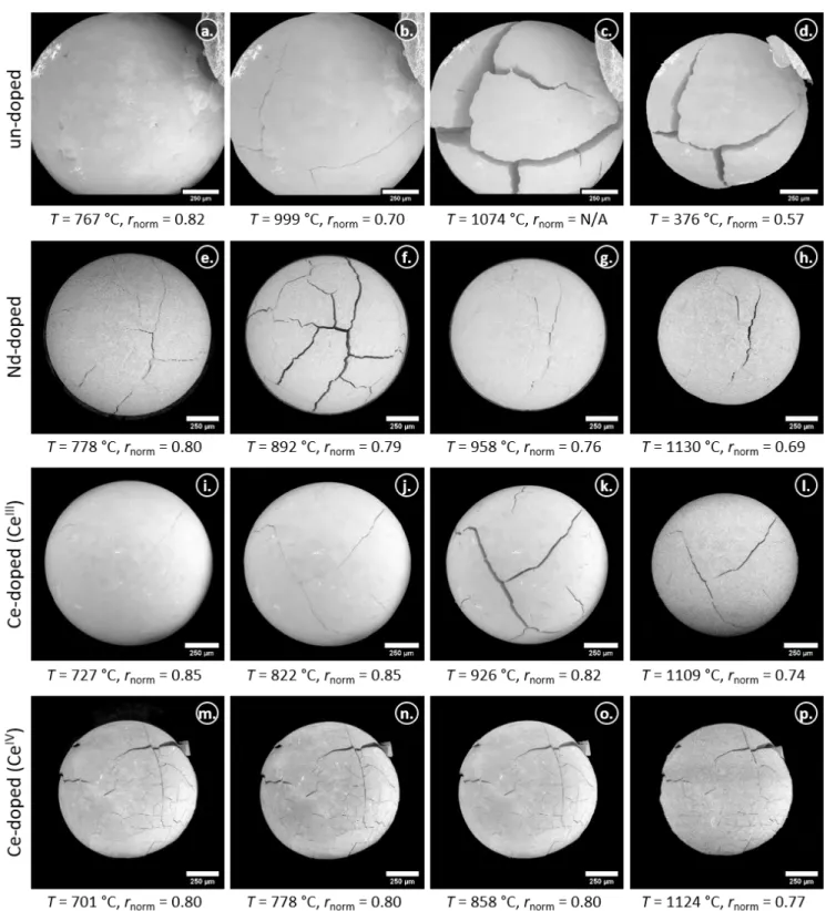
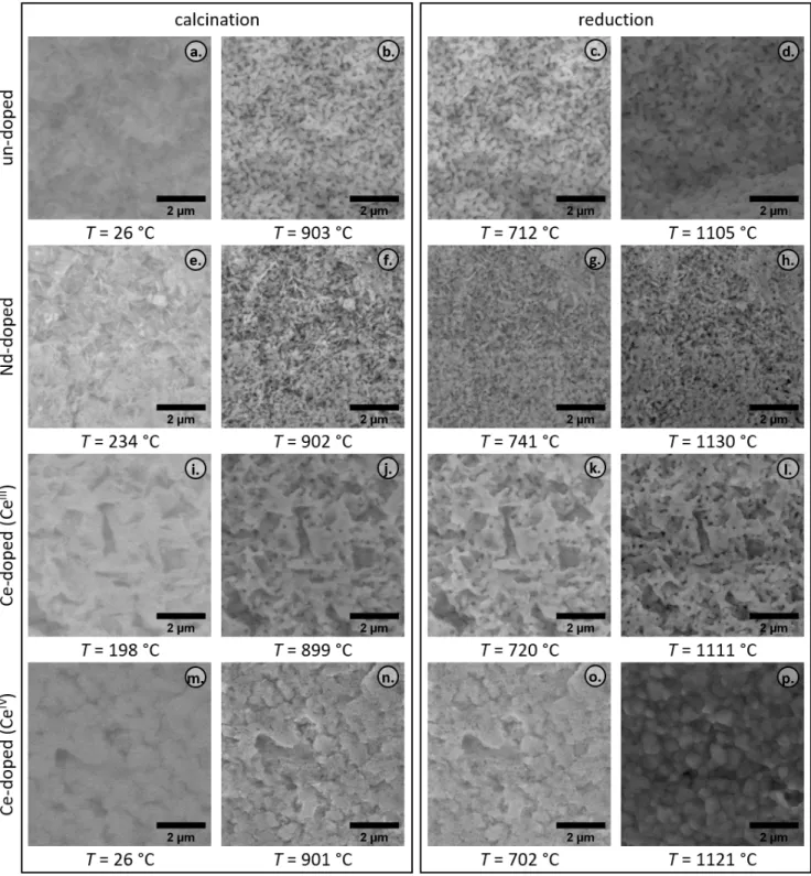
Micrographs of the particles recorded during the HT-SEM investigations are summarised in figure 4 for the calcination in air. As experimental parameters were optimised during the study of the un-doped particle, only few images were recorded at low magnification compared to the doped particles. The left column of figure 4 shows one particle of each composition at its initial state at room temperature. The 2nd and 3rd column show the same particles during the heating, and the right column towards the end of the calcinations’ isothermal plateau at the maximum temperature of about 900 °C. In the case of 290
the un-doped material, the initial image was taken at an elevated temperature (figure 4a) and the final one during the cooling to room temperature (figure 4d), they were added to figure 4 due to a comparable magnification to the doped particles. The corresponding temperatures and determined radii, normalised to the radii measured on the initial image (figure 4, left column), are shown as well. The absolute initial radii were determined as 851.2µm, 626.3 µm, 726.5 µm and 671.5 µm for the un-doped and Ln-doped ADU microspheres prepared with the NdIII, CeIIIand CeIVdopant precursors, respectively.
295
Comparable particle shrinkages were found during the calcination in air. Normalised radii ranging between 0.81 and 0.86 were measured at the end of the calcination. The largest difference occurred for the Ce-doped particle prepared with CeIV
and the smallest for the Ce-doped particle prepared with CeIII. The relative radii measured for the un-doped and Nd-doped
composition, were both found to be 0.82 at the end of the calcination. Even though the relative radii differences during the entire thermal treatment step were comparable, the Ce-doped particle prepared with CeIV showed a significantly different
300
behaviour during the heating to 550 °C (figure 4, second column). The formation of cracks on the particle surfaces were observed for all compositions, but for the latter it was much more emphasised and went along with a remarkable shrinkage. The normalised particle radii of the heating to 550 °C within the calcination in air are plotted in figure 5 as function of temperature, the normalised radii after the calcination are included as arrows.
Figure 4: Micrographs of the un-doped and doped particles during the calcination in air. The left column shows one particle of each composition at its initial state, while column 2 and 3 show the same particles during the heating. The images of the right column show the particles towards the end of the isothermal plateau at the maximum temperature of about 900 °C, with an exception for the un-doped particle (taken during cooling at 332 °C, please note also the larger magnifications that had to be used for the un-doped material).
100
200
300
400
500
Temperature / °C
0.8
0.9
1.0
r(particle) r(particle)
initial
r
norm.
after calcination
un-doped
Nd-doped
Ce-doped (Ce
III
)
Ce-doped (Ce
IV
)
Figure 5: Normalised particle radii during the heating to 550 °C within the calcination in air as function of the temperature (temperature profile shown in figure 6a), as well as the normalised particle radii after the calcination in air (arrows).
While all other compositions have a relative radius of about 0.9 between 500 °C and 550 °C, the radius of the Ce-doped 305
particle (CeIV) shrunk already to a normalised radius of 0.81 (figure 5 and figure 4n), with the most emphasised shrinkage
occurring below 350 °C. These results match well with the findings of the TG-DSC analyses, where we observed significant mass losses going along with strong exothermal reactions for the Ce-doped particle prepared with CeIVin the same temperature
region (figure 3b and 3c).
The data series obtained from the HT-SEM investigations were split into individual series for the two different thermal 310
treatment steps. Each was offset corrected to match the temperature profile applied during the TG-DSC analyses and to allow a comparison of the data as a function of time. For the calcination in air, the heat up segment to 900 °C was used for this purpose, while the sintering was aligned to the time when a reducing atmosphere was introduced. The temperatures of the individual HT-SEM measurements are shown as a function of the offset corrected times in figure 6a and 6d, for the calcination in air and sintering under reducing conditions, respectively. We observe deviations for temperatures lower than 450 °C and times lower 315
than 60 min within the calcination step, but those results were already described in figure 5 as a function of temperature. The offset corrected data for higher temperatures (Tmax: 902 °C to 905 °C) and times agree well to each other.
In the case of the sintering under reducing conditions, the deviations prior the introduction of the N2:H2mixture (421 min) are negligible, since no significant expansion or contraction was observed during the cooling to room temperature in air and subsequent heating to 700 °C in N2. For the heating process in the reducing environment, the profiles are comparable besides 320
slightly different isothermal holding times at the maximum temperatures (1112 °C to 1131 °C). The in-situ particle radii, normalised to the initial radii, measured during both treatment steps within the HT-SEM analyses are plotted in figure 6b and 6e. The development of the particle volumes, calculated from the radii assuming a spherical geometry, normalised to the final particle volumes are shown in figure 6c and 6f.
0
500
1000
T / °C
air
calcination
a.
0.6
0.8
1.0
r(particle) r(particle)
initialb.
50
100
150
200
Time / min
2
4
V(particle) V(particle)
finalc.
N2
N2:H2
reduction
d.
e.
400
500
600
Time / min
f.
un-doped
Nd-doped
Ce-doped (Ce
III)
Ce-doped (Ce
IV)
Figure 6: Temperatures measured for the calcination (a) and reduction (d) during the HT-SEM analyses, in-situ particle radii normalised to initial radii (b, e), as well as the resulting particle volumes normalised to the final volumes (c, f) as function of the offset corrected time.
During the calcination in air, we observe a second significant shrinkage step at temperatures above 700 °C (figure 6b and 325
6c, about 100 min), which is for all compositions smaller than the shrinkage observed up to 550 °C. The micrographs taken during this step (figure 4, third column) show besides the particle shrinkage that the cracks and gaps, formerly noticed, are less emphasised and closed for the un-doped material.
The results for the reduction of the particles in the N2:H2gas mixture (figure 6e and 6f) show prior to the change of the atmosphere to reducing conditions comparable normalised radii to those observed towards the end of the calcination (figure 6b 330
and 6e). Micrographs of the particles during the sintering in the reducing environment are summarised in figure 7, the left column shows images recorded after the introduction of the N2:H2gas mixture at temperatures between 700 °C and 770 °C, the particle radii determined agree well to the radii of the calcined particles. During the treatment in the reducing environment, a shrinkage from normalised radii between 0.80 and 0.85 (figure 7, left column) to radii ranging between 0.57 and 0.77 (figure 7, right column) was observed. The largest difference was measured for the un-doped compound (0.25), while the 335
smallest shrinkage occurred for the Ce-doped composition prepared with CeIV (0.03). For the doped compositions prepared
with the trivalent dopant precursors, comparable differences of 0.11 were observed. Normalised radii differences of up to 0.02 during the further process of the sintering (figure 6e) indicate no remarkable shrinkage after 500 min, which corresponds to an N2:H2exposure time of about 80 min at a temperature of 1112 °C, with an exception for the Nd-doped composition where a slightly higher maximum temperature was applied (1128 °C). The comparison of the individual particles to each other is 340
better reflected by the particle volume normalised to the final volume, as shown in figure 6f.
4. Discussion
Samples of the dried gels of the current work were characterised in our previous studies by XRD. The diffraction pattern of the un-doped composition was compared to reference pattern [23] and identified as 3UO3·2NH3·4H2O [16], using the described preparation conditions. A comparable XRD diffraction pattern was observed for the 10 mol% Nd doped compound. 345
Intensity variations were observed, but no additional reflections compared to the un-doped composition were recognised [15]. A significantly different degree of crystallinity was observed for the different Ce precursors. CeIIIled to patterns comparable to
the Nd-doped particles, while a large fraction of an amorphous phase appeared to be present in the compositions prepared with CeIV. However, also no additional reflections compared to the un-doped particles were observed for the Ce-doped material
[15], allowing us to conclude that the dopant is either incorporated into the ADU matrix, or present as an amorphous phase. 350
Therefore, we assume that the initial sample material of this study corresponds to ADU with 3UO3·2NH3·4H2O stoichiometry, or Nd- or Ce-doped 3UO3·2NH3·4H2O, respectively.
4.1. Structural changes during calcination in air
The comparable differences between the initial ex-situ and initial in-situ masses observed during the TG-DSC measure-ments (−3.9(4) wt% to −3.5(4) wt%) point to a similar amount of loosely adsorbed water molecules in the initial (Ln-doped) 355
3UO3·2NH3·4H2O material.
During the thermal decomposition of the compounds in air, three major mass loss steps were recognised. The first two can be assigned to the removal of water and ammonia [16]. The most significant mass drops occurred at temperatures of about 135 °C going along with an endothermic DSC signal, and at about 275 °C, accompanied with one exothermic reaction for the un-doped material and the doped particles prepared using the trivalent precursors (figure 3a and 3b). For the doped 360
Figure 7: Micrographs of the un-doped and doped particles during the sintering in reducing atmosphere. The left row shows one particle of each composition
after the introduction of the N2:H2gas mixture. The 2ndand 3rdrows show the same particles during the heating to the maximum temperature and the right
column shows the particles towards the end of the isothermal plateau at the maximum temperature of about 1100 °C, with an exception for the un-doped particle (taken during cooling at 376 °C, please note also the larger magnifications that had to be used for the un-doped material).
composition prepared with CeIV, the DSC signal indicates at least four exothermic reactions for the second step, occurring
at temperatures of 241 °C, 259 °C, 275 °C and 291 °C, and result in a more pronounced mass loss during the second major mass loss step. The observations match to the thermal decomposition profile of HMTA/urea mixtures [24, 25], which points to residuals of the gelation agents in the particle and an ineffective washing. Similar findings were made for yttria-stabilised zirconia(-ceria) microspheres [24, 26]. Amorphous phases and low porosity prevent the volatile decomposition products to 365
escape the particles and lead to crack formation [27]. An increased HMTA content in the sol resulted in more pore formation, leading to less severe cracking [28]. Moreover, it was demonstrated that the remaining organics can be removed from the particles by a pressurised water treatment of the gelled spheres [26]. Katalenich [25] applied the latter successfully for ceria microspheres, also prepared with diammonium cerium(IV) nitrate as precursor. TGA of the dried residue from the water treatment showed about 90 wt% mass loss up to 400 °C, supporting the assumption of an ineffective washing for the Ce doped 370
batch prepared with the CeIVdopant precursor.
Close-ups of the particle surfaces are presented in figure 8. Micrographs taken at the beginning of the calcination in air show the initial state (left column) and the same region of the surface at about 900 °C towards the end of the isotherm is presented in the second column. We observe agglomerates for all compositions, the micrograph taken for the composition prepared with CeIVindicates a poor crystallinity (figure 8m). The latter agrees with the XRD patterns of the initial material,
375
where a large fraction of amorphous material was observed for the Ce-doped composition prepared with CeIV[15]. It further
supports the explanation for the crack formation, volatile decomposition products of the gelation agents are hindered to escape the particle, which results in the fracturing.
The different decomposition behaviour of the composition prepared with CeIV, compared to all other examined compounds,
was also confirmed by the particle shrinkage. The other compositions have a relative radius of 0.9 between 500 °C and 550 °C 380
(figure 5), whereas the radius of the Ce-doped particle prepared with CeIV shrunk already to a normalised radius of 0.81,
with the most pronounced shrinkage below 350 °C. It agrees to the observed mass difference and supports the assumption of retaining gelation agents. Clearly, microspheres prepared by the sol-gel method via IG with a CeIVdopant precursor have
a different crystallinity and/or initial composition than particles prepared with a CeIII dopant precursor. It is most likely a
consequence of the diammonium cerium nitrates’ n(NO3–)
n(Ce) ratio of 6 as compared to 3, which applies for the trivalent lanthanide 385
dopant precursors and affects the crystallinity [27].
Moreover, we observe a correlation of the decomposition temperatures with the gap development of initially formed cracks. A summary for the un-doped particle is given in figure 9, the closing and opening observed within the first 5 subfigures corresponds to the H2O and NH3release. The gap opening of the third subfigure was observed at 178 °C, and can be assigned to the first major mass loss step observed by TG-DSC. During further heating, this gap closes again. The second major mass 390
loss step started at the temperature of the fourth subfigure (figure 9, 236 °C), but the gap closes further and is not notable at 422 °C anymore. A similar behaviour was observed for the doped particles, prepared with the trivalent Ln precursors.
Comparable masses at a temperature of 550 °C (table 2, m(83.5 min)in-situ) indicate similar compounds prior to the con-version of the UO3matrix to α-U3O8[16], which is the third major mass loss step during the calcination of the particles in air. The differences caused by the conversion are higher than the theoretically expected ones. Theoretical mass differences 395
of −1.90 wt% (un-doped), −1.77 wt% (10 mol% Nd-doped) −1.78 wt% (10 mol% Ce doped) were calculated, assuming solid solution of α-U3O8/Nd2O3and α-U3O8/CeO2at a temperature of 665 °C. However, as result of the mentioned inconsistencies for the conversion observed in the ground and as-produced sample material and too many assumptions, no further attention
Figure 8: Close-ups of the particle surfaces recorded by HT-SEM during the thermal treatment. The left column shows the particle surface at the beginning
of the calcination in air at its initial state, while the 2ndcolumn shows the same region of the surface at T
maxtowards the end of the isotherm. The 3rd
column was taken at about 750 °C during the sintering after the introduction of the reducing atmosphere and the last column at about 1100 °C at the end of the sintering isotherm.
Figure 9: Formation of cracks in the un-doped particle and their development during the calcination in air (Tmax ≈ 900 °C) and sintering in reducing
atmosphere (Tmax≈ 1100 °C).
is given to this matter and the general decomposition behaviour of un-doped material, described in our former study [16], could be confirmed. The compositions prepared with the trivalent dopant precursor behave similarly, slight mass variations 400
were observed, but the data do not indicate additional reactions during the decomposition in air compared to the un-doped material and the TGA and TG-DSC results of our former study [16]. Since no further gradual mass loss occurred during the calcination in air, the TG-DSC results imply that a treatment temperature of 700 °C is sufficient to form the same product, but the HT-SEM results demonstrated for all particles, besides those prepared with CeIV, a further significant shrinkage during the
heating and the isothermal segment at 900 °C. The shrinkage occurs in the form of a step function for the un-doped material 405
and microspheres prepared with the trivalent dopant precursors, which is most likely caused by the formation of the α-U3O8 matrix (figure 6b). It is followed by a slow, gradual densification, which is also reflected in the agglomerates. However, it results in quite porous material for the un-doped particle, but individual crystallites can be recognised (figure 8b). The shrink-age of the agglomerates was also observed for the compositions prepared with the trivalent dopant precursors (figure 8f and 8j), both compositions are porous as well. The formation of crystallites can also be seen for the Nd-doped composition, but 410
is less emphasised for the Ce-doped material prepared with CeIII, while less pores were observed for the Ce-doped particle
prepared with CeIV(figure 8n). During the isothermal segment at 900 °C and the subsequent cooling to 265 °C, the gaps of the
initially observed cracks were not visible (figure 9). While they were noticed slightly later at a temperature of 248 °C during the cooling.
The presence of comparable compounds after the calcination was confirmed by XRD (figure 1). No additional reflections 415
occurred in the diffraction pattern of the doped compounds, allowing us to assume that the calcination products are solid solution of α-U3O8/Nd2O3and α-U3O8/CeO2. The lattice parameters determined for the un-doped compound are comparable to values published by Loopstra [20], who described the α-U3O8phase with the C2mm space group (non-standard setting of space group Amm2) and an orthorhombic symmetry. He published lattice parameters of a= 0.6716 nm, b = 1.1960 nm and c= 0.4147 nm. Our lattice parameters (table 1) refer to the standard setting in the Amm2 space group, resulting in a swap of 420
the a with c parameter.
4.2. Structural changes during sintering in reducing atmosphere
The introduction of the reducing atmosphere during the thermal treatment caused a quite rapid transition from α-U3O8 to UO2±xat 700 °C (figure 3c and 3d) completed within less than 10 min after exposure to Ar:H2(96:4). For the Ce-doped
material prepared with the CeIV precursor, this reduction took about 45 min. The corresponding shrinkage was measured
425
significantly later by HT-SEM (figure 6e and 6f) and occurred during a dynamic segment at elevated temperatures. A com-parable behaviour was observed by Clavier et al. for ThO2compounds [29]. The mass losses of −3.6(4) wt%, measured in the un-doped sample (ground and as-produced), the smaller mass loss of −3.5(4) wt% of the Nd-doped composition, and the higher difference of −3.7(5) wt% for the Ce-doped material (both precursors), show only marginal differences and are within their uncertainties, but match the trend for the expected mass losses of −3.80 wt%, −3.54 wt% and −3.85 wt%, respectively. 430
The theoretical values were calculated assuming the presence of Nd2O3or CeO2prior to the reduction and Nd2O3or Ce2O3 afterwards. Reaction enthalpies for the conversion of α-U3O8to UO2±x were determined as −156(5) kJ mol−1 for the un-doped material (as-produced sample: −160(5) kJ mol−1), −164(6) kJ mol−1for the Nd-doped sample, and −161(6) kJ mol−1 and −154(6) kJ mol−1for the α-U3O8in the Ce-doped material prepared with the CeIIIand CeIVprecursors, respectively. We observe small deviations for the reaction enthalpies, indicating no, or only a marginal, contribution of the dopant to the reaction 435
enthalpy.
For the particles prepared using the trivalent dopant precursors, we observed already comparable shrinkage rates during the isothermal segment of the calcination, if we consider the data standardised to the final particle volumes (figure 6c). Both compounds follow the same trend during the sintering, while the shrinkage of the un-doped material is more emphasised. The initially observed cracks of the un-doped particle (figure 9) became more pronounced during the heating in reducing 440
atmosphere and show a maximum distance between the fragments at about 959 °C, which decreased during further heating. However, the partially open cracks remain present during the subsequent shrinkage and the cooling to room temperature. The significantly smaller shrinkage rate of the Ce-doped particle with CeIVprepared during the reaction might be explained
by its fragmented structure caused by the rapid significant shrinkage during the exothermic reactions within the calcination. Moreover, we showed that less pores were present already after the calcination (figure 8n), compared to the other compounds, 445
which might hinder a H2diffusion into the microsphere and caused the slower reduction. Figure 8 includes also the particle surfaces at about 750 °C during the sintering after the introduction of the reducing atmosphere (third column) and at the end of the sintering isotherm at about 1100 °C (right column). The trend observed during the calcination remained for the sintering, while the un-doped and doped particles prepared with trivalent dopant precursors exhibit a large amount of pores, we see a quite dense surface for the composition prepared with CeIV. Grain growth was observed for all compositions, but significantly
450
larger grains were formed for the Ce-doped composition prepared with the tetravalent dopant precursor.
The in-situ behaviour of the particles during the thermal treatment applied within this study is summarised in figure 10, correlating the HT-SEM results with the TG-DSC results. The subplots (a) and (e) show the temperatures of the TG-DSC and HT-SEM analyses as function of the (offset) corrected times for the calcination, and the reduction, respectively. The masses obtained during the TG-DSC measurements were normalised to average masses of dried particles, determined within 455
our previous study [15, 30], and presented in figure 10b and 10f. In the same study average particle radii and volumes were determined, which we used to normalise the radii measured in the HT-SEM investigations and to calculate average particles volumes, assuming a spherical shape (figure 10c and 10g). Both series were combined to determine average in-situ particle densities for both thermal treatment steps, which are presented in figure 10d and 10h. It should be noted that the data contain some uncertainties, especially for temperatures below 450 °C and times < 60 min, and for the un-doped composition, where 460
the initial HT-SEM image was recorded at 91 °C. Figure 10 is intended to represent the tendencial behaviour for an average particle of each of the compositions during thermal treatment, and shows that the contribution of the mass changes to the
density is negligible. The particles’ density is mainly impacted by the shrinkage.
Volume shrinkage factors normalised to the final volume of 5.3, 3.0, 2.6 and 2.3 for the un-doped, Nd-doped, Ce-doped (CeIII) and Ce-doped (CeIV) particles were determined after the treatment, carried out in this study (figure 6c and 6f). The
465
results do not match to volume shrinkage factors determined for particles from identical batches after a sintering for 10 h at 1600 °C in Ar:H2with an addition of Ar:O2, corresponding to an oxygen potential of about −420 kJ mol−1, where values of about 7.5, 8.0, 5.7 and 3.0 were found, respectively [15]. The significantly larger volume shrinkage factors show that the investigations carried out in this work describe the structural changes of Nd- and Ce-doped ADU microspheres during the conversion to U1−yLnyO2±x very detailed for temperatures up to about 1100 °C, but obviously, sintering is far from being 470
complete at 1100 °C. The presence of U1−yLnyO2±xsolid solutions was demonstrated by XRD for all doped compositions analysed in this work, after the sintering for 10 h at 1600 °C in Ar:H2with an addition of Ar:O2(about −420 kJ mol−1oxygen potential) [15]. SEM analyses of the sintered products were carried out as well, and images adapted from those published in the previous study [15] are presented in figure 11. We can see that the sintering at higher temperature for 10 h in the described atmosphere led to intact and spherically shaped particles with no notable cracks for the un-doped and doped particles prepared 475
with the trivalent dopant precursors (figure 11a to 11c). Significantly slower heating rates of 1.5 °C min−1and 5 °C min−1were applied during the calcination and sintering, respectively. This might have led to less crack formation during the calcination and the longer sintering time to healing. The Ce-doped particle prepared with CeIV as dopant precursor (figure 11d) has a
deformed spherical shape, but is an integer particle. However, it exhibits a large number of cracks on the surface.
5. Conclusions 480
The structural changes of un-doped, 10 mol% Nd- and 10 mol% Ce-doped ammonium diuranate microspheres during the conversion into U1−yLnyO2±xwere investigated in detail by a combination of in-situ TG-DSC and HT-SEM. A thermal treat-ment consisting of a calcination in air at 900 °C for one hour and a sintering under reducing conditions with temperatures up to about 1100 °C for two hours was carried out. Within the heating of the calcination with 10 °C min−1, the formation of cracks and a shrinkage of the particles was observed, slower heating rates (e. g. 1.5 °C min−1) will most likely result in less severe 485
crack formation. The Ce-doped particle prepared with the tetravalent precursor behaved considerably different than the one prepared with the trivalent precursor, pointing to a different crystallinity and/or initial composition and revealed a significant impact of the dopant precursor on the gel formed during the IG synthesis. The shrinkage for higher temperatures is caused mainly by the densification of the material, and the conversion of the UO3matrix to an α-U3O8matrix has no noticeable influ-ence. The calcined products were identified as (Ln-doped) α-U3O8by XRD. Upon the introduction of a reducing atmosphere, 490
a sudden mass loss was recognised in the material, while a shrinkage occurred significantly later, pointing out that the shrink-age observed within the sintering is also controlled by a general densification of the material and insignificantly by the volume change due to the transition of the orthorhombic α-U3O8phase to the cubic UO2±xphase. Comparable particle radii during the isotherm at about 1100 °C indicate that the temperature has a higher impact on the shrinkage than the dwell time at a certain temperature. The Nd- and Ce-doped particles prepared with trivalent dopant precursors showed a comparable decomposition 495
and sintering behaviour besides some minor differences during the release of water and ammonia within the calcination. The investigations carried out in this work describe the structural changes of Nd- and Ce-doped ADU microspheres during the conversion to U1−yLnyO2±xvery detailed for temperatures up to about 1100 °C. When applying commonly used sintering conditions around 1600 °C with longer dwell times, significantly larger volume shrinkage factors can be obtained, leading
0
500
1000
T / °C
calcination
a.
3.0
3.5
m
/ mg
air
b.
0.5
1.0
1.5
V / mm
3
air
c.
50
100
150
Time / min
2.5
5.0
7.5
/ g cm
3
d.
reduction
e.
TG-DSC
HT-SEM un-doped
HT-SEM Nd-doped
HT-SEM Ce-doped (Ce
III)
HT-SEM Ce-doped (Ce
IV)
Ar Ar:H2
f.
un-doped
Nd-doped
Ce-doped (Ce
III)
Ce-doped (Ce
IV)
N2
N2:H2
g.
400
450
500
550
Time / min
h.
Figure 10: Temperatures measured during the TG-DSC and HT-SEM analyses for the calcination in air (a) and sintering in reducing atmosphere (e). Masses obtained during the TG-DSC measurements standardised to the average particle masses (b, f) and volumes derived from radii measured in the HT-SEM investigations standardised to the average particle volumes (c, g), as well as resulting average in-situ particle densities during both thermal treatment steps (d, h).