HAL Id: cea-01890264
https://hal-cea.archives-ouvertes.fr/cea-01890264
Submitted on 8 Oct 2018
HAL is a multi-disciplinary open access
archive for the deposit and dissemination of
sci-entific research documents, whether they are
pub-lished or not. The documents may come from
teaching and research institutions in France or
abroad, or from public or private research centers.
L’archive ouverte pluridisciplinaire HAL, est
destinée au dépôt et à la diffusion de documents
scientifiques de niveau recherche, publiés ou non,
émanant des établissements d’enseignement et de
recherche français ou étrangers, des laboratoires
publics ou privés.
Magnetocardiography with sensors based on giant
magnetoresistance
M. Pannetier-Lecoeur, L. Parkkonen, N. Sergeeva-Chollet, H. Polovy, C.
Fermon, C. Fowley
To cite this version:
M. Pannetier-Lecoeur, L. Parkkonen, N. Sergeeva-Chollet, H. Polovy, C. Fermon, et al..
Magnetocar-diography with sensors based on giant magnetoresistance. Applied Physics Letters, American Institute
of Physics, 2011, 98, pp.153705. �10.1063/1.3575591�. �cea-01890264�
Magnetocardiography with sensors based on giant magnetoresistance
M. Pannetier-Lecoeur, L. Parkkonen, N. Sergeeva-Chollet, H. Polovy, C. Fermon, and C. FowleyCitation: Appl. Phys. Lett. 98, 153705 (2011); doi: 10.1063/1.3575591 View online: https://doi.org/10.1063/1.3575591
View Table of Contents: http://aip.scitation.org/toc/apl/98/15 Published by the American Institute of Physics
Articles you may be interested in
Magnetocardiogram measured by fundamental mode orthogonal fluxgate array Journal of Applied Physics 117, 17B322 (2015); 10.1063/1.4918958
Tunneling magnetoresistance sensor with pT level 1/f magnetic noise AIP Advances 7, 056676 (2017); 10.1063/1.4978465
Low-frequency noise measurements on commercial magnetoresistive magnetic field sensors Journal of Applied Physics 97, 10Q107 (2005); 10.1063/1.1861375
Tunnel magnetoresistance of 604% at by suppression of Ta diffusion in pseudo-spin-valves annealed at high temperature
Applied Physics Letters 93, 082508 (2008); 10.1063/1.2976435
Progress toward a thousandfold reduction in noise in magnetic sensors using an ac microelectromechanical system flux concentrator (invited)
Journal of Applied Physics 99, 08B317 (2006); 10.1063/1.2170067 Magnetoencephalography with an atomic magnetometer
Magnetocardiography with sensors based on giant magnetoresistance
M. Pannetier-Lecoeur,1,a兲L. Parkkonen,1,b兲N. Sergeeva-Chollet,1H. Polovy,1C. Fermon,1and C. Fowley2
1
DSM/IRAMIS/SPEC, CNRS URA 2464, CEA Saclay, 91191 Gif-sur-Yvette, France
2
CRANN, Trinity College, Dublin 2, Ireland
共Received 19 January 2011; accepted 10 March 2011; published online 14 April 2011兲
Biomagnetic signals, mostly due to the electrical activity in the body, are very weak and they can only be detected by the most sensitive magnetometers, such as Superconducting Quantum Interference Devices共SQUIDs兲. We report here biomagnetic recordings with hybrid sensors based on Giant MagnetoResistance共GMR兲. We recorded magnetic signatures of the electric activity of the human heart共magnetocardiography兲 in healthy volunteers. The P-wave and QRS complex, known from the corresponding electric recordings, are clearly visible in the recordings after an averaging time of about 1 min. Multiple recordings at different locations over the chest yielded a dipolar magnetic field map and allowed localizing the underlying current sources. The sensitivity of the GMR-based sensors is now approaching that of SQUIDs and paves way for spin electronics devices for functional imaging of the body. © 2011 American Institute of Physics.关doi:10.1063/1.3575591兴
Many living organisms generate weak but measurable magnetic fields. These biomagnetic signals can be either static fields due to dc currents or small magnetic particles in the tissues or low-frequency fields due to transient or oscil-latory electric activity. In humans, the two most studied bio-magnetic signal sources are the brain 共magnetoencephalog-raphy or MEG兲 and the heart 共magnetocardiog共magnetoencephalog-raphy or MCG兲. MEG and MCG signals result from the electric cur-rents flowing in active nerve cells in the brain and cardiac muscle, respectively. The temporal accuracy of these mea-surements is very high共in the ms range兲, and recording the signals at multiple locations typically allows localizing the generators.
MEG and MCG are completely noninvasive and even contactless, allowing measurements without the use of elec-trodes, which is a benefit when studying infants, for ex-ample. Furthermore, unlike electric signals, magnetic signals are not distorted by the conductivity changes between differ-ent tissues.
Since biomagnetic signals are very weak, typically few tens of picoteslas共1 pT=10−12 T兲 for MCG and few tens of femtoteslas共1 fT=10−15 T兲 for MEG, only few sensor types have been used so far for measuring them. Superconducting Quantum Interference Devices 共SQUIDs兲1 have been the sensor of choice for MEG共Ref.2兲 and MCG,3thanks to their exquisite sensitivity at low frequencies. Commercial MEG systems employ liquid Helium-cooled low-Tc Nb-based SQUIDs, which can reach sensitivities of few fT/ 冑Hz down to 1 Hz and can be manufactured with reproducible proper-ties. High-TcSQUIDs have been used also for biomagnetic recordings4,5 but their application has been limited by the order-of-magnitude larger noise levels, and by the difficulties in realizing durable Josephson junctions in high-Tc supercon-ducting material.
Several emerging sensor technologies for detecting ex-tremely weak magnetic fields at low frequencies have been
proposed during the past few years. Spin exchange relaxation-free atomic magnetometers exhibit femtotesla sensitivity6and recordings of biomagnetic signals have been demonstrated.7,8
Thin-film technology allows precise fabrication of arrays of sensors using patterning techniques developed for semi-conductor industry. Exploiting this technology and spin elec-tronics, we have previously developed a magnetometer whose sensitivity reaches the femtotesla range.9This sensor combines a spin valve to a superconducting flux-to-field transformer and can achieve white noise levels of a few fem-toteslas. As the sensor does not contain a junction, the super-conducting loop can be made either of low- or high-Tc ma-terial without difficulty.
A magnetic field applied to the superconducting loop gives rise to a supercurrent which flows in the loop to coun-teract the applied field. Part of the loop is narrowed关see Fig.
1共a兲兴 to increase the local current density, resulting in a local amplification of the applied field by the ratio of the loop size and constriction width. The amplified field can be detected by magnetoresistive sensors located on top or below the con-striction. Giant MagnetoResistance共GMR兲 共Refs.10and11兲
and Tunnel MagnetoResistance共TMR兲 共Refs.12and13兲
de-vices are suitable because of their high sensitivity to in-plane fields.
Our sensor comprised four GMR spin valves with the following composition: Ta共5兲 / NiFe共3.5兲 / CoFe共1.5兲 / Cu共2.9兲 / CoFe共2.5兲 / IrMn共10兲 / Ta共5兲; the thicknesses are in nanometers. The four GMR elements were patterned by con-ventional photolithography in a yoke shape to prevent the formation of magnetic domains in the sensing area.14 The GMRs were configured as a Wheatstone bridge. The large Niobium loop was deposited by sputtering. The GMR stacks and the loop were electrically isolated by a 300-nm Si3N4 layer. For the MCG measurements, the sensor was located at the bottom of a fiberglass dewar and immersed in liquid he-lium.
The GMRs were biased with a current of about 0.3 mA. The sensitivity of the mixed sensor was of 6000 V/T for this bias current; the resulting voltage was measured by a
low-a兲Author to whom correspondence should be addressed. Electronic mail: [email protected].
b兲Also at Elekta Oy, Helsinki, Finland.
APPLIED PHYSICS LETTERS 98, 153705共2011兲
noise preamplifier stage with a gain of 500 共custom-built around INA103 with a voltage noise level of 1.2 nV/ 冑Hz兲 operating at room temperature. In the thermal noise, the sen-sitivity is limited by the preamplifier noise, leading to an equivalent field sensitivity of 200 fT/ 冑Hz. However, at low-frequency the sensitivity is limited by the 1/f noise of the GMRs and gives a noise of 17 nV/ 冑Hz at 1 Hz, which corresponds to 3 pT/ 冑Hz at 1 Hz 关see Fig.1共b兲兴. Secondary amplification 共gain 100兲 and filtering 共pass-band 0.1–300 Hz兲 was performed by a Stanford Research Systems 共Sunny-vale, CA, USA兲 model 560 low-noise amplifier. The signal was then fed to an extra analog input of the acquisition sys-tem of a commercial 306-channel MEG syssys-tem共Elekta Oy,15 Helsinki, Finland兲. An electrocardiographic 共ECG兲 signal was acquired simultaneously by a pair of surface electrodes attached to the wrists of the subject and connected to a bi-polar channel of the EEG amplifier and acquisition system of the Elekta MEG device. The MCG and ECG signals were filtered to 0.1–330 Hz and sampled simultaneously at 1 kHz. The acquisition system also provided the possibility for on-line monitoring of the signals 共Fig.2兲.
Since the MCG signals are on the order of a few tens of pT, external magnetic interference can easily mask them, particularly when using a magnetometer sensor, which— unlike a gradiometer—does not provide any additional at-tenuation of remote sources. Therefore, we performed the recordings in the magnetically shielded room 共MSR兲 of the MEG facility of the NeuroSpin center of CEA/Saclay, France. The MSR共MaxShield™ by Elekta Oy15兲 comprised a single shell made of interleaved mu-metal and Aluminum plates. The internal active compensation system was not used.
The subject laid down on his/her back, with chest right below the dewar but not touching it. The distance between the sensor and the skin was 25–30 mm. The dewar was
manually translated in the horizontal plane to cover a 6-by-6 point grid of measurement locations. The spacing was 3 cm in the left–right direction and 5 cm in the foot–head direction 共except that the lowest rows were separated only by 2 and 3 cm due to space constraints兲, and the grid was displaced to the left of the subject by 1.5 cm; the convention was adapted from the work of Saarinen et al.16 During the measurement, the dewar position was read with respect to a reference point using two scales, and these positions were later inserted in the data file to enable estimating field maps and source loca-tions.
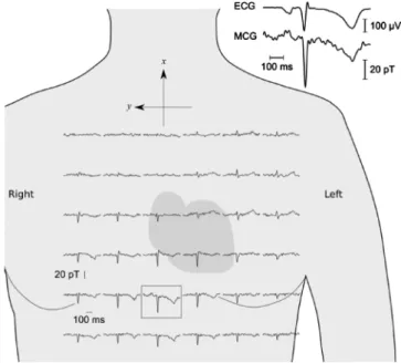
The MCG signal was recorded for about one minute per location, together with the ECG. The resulting 36 continuous recordings for each subject were then separately averaged by using the QRS peak onset of the conditioned ECG signal as the trigger and by rejecting epochs with excessively large 共⬎60 pT兲 signal variation due to external perturbation. The number of clean epochs varied from 46 to 54 per location: the variation was due to the rejections. The averages were merged into one multi-channel file that contained the dewar positions as the channel locations. The characteristic compo-nents of normal ECG, the P-wave, QRS complex and T-wave,16,17are all present in our magnetic data; see Fig.3. The spatial variation in the signal shape is also clearly vis-ible, demonstrating the added value of magnetic recordings with respect to ECG.
FIG. 1. 共Color online兲 共a兲 Schematic diagram of the sensor: four GMR elements are mounted on a constric-tion of the large Niobium loop. The GMRs are wired to form a Wheatstone bridge. Dimensions are not to scale. 共b兲 Field sensitivity at 4 K extracted from the noise power spectrum of the mixed sensor. Note that in the thermal noise共f⬎1 kHz兲, the limitation is due to the preamplifier noise, which is of 1.7 nV/ 冑Hz 共and cor-responds to 200 fT/ 冑Hz兲. Power line peak at 50 Hz is well visible on the graph.
FIG. 2. 共Color online兲 The experimental setup 共ECG not shown here兲.
FIG. 3. MCG signals measured at multiple locations on a single subject. The enclosed MCG trace is shown enlarged with the ECG signal. Pass-band 0.1–40 Hz. The position of the traces with respect to the heart is only approximate.
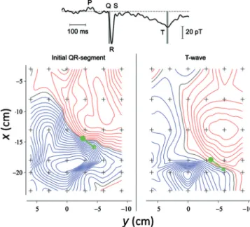
The magnetic field map 共Fig.4兲 shows the polarity
in-version for the initial QR-segment approximately along the diagonal of the measurement grid, suggesting a dipolar source with a similar orientation. This pattern changes for the T-wave, indicating a partially separate generator.
We performed simple equivalent current dipole model-ing of the MCG components usmodel-ing conductmodel-ing half space as the conductor model. For the initial QR-segment, R-peak, and T-wave, the fitted dipoles explained 84%, 97%, and 84% 共goodness of fit兲 of the spatial variation in the signal pattern and yielded dipole moments of 0.82 Am, 3.0 Am, and 1.6 Am, respectively. Figure4shows the QR-segment and T-wave dipole locations and orientations projected on the sensor plane.
In summary, we have performed biomagnetic measure-ments with GMR-based sensors. We recorded MCG signals at multiple locations on a healthy volunteer, estimated a magnetic field map, and succeeded in modeling the signal patterns with equivalent current dipoles with a small residual variance. Further improvements in the setup, including the use of TMR elements for the field sensing, and reducing the distance from the sensor to the room temperature surface of the dewar, may allow detection of MEG responses which are orders of magnitude weaker than MCG signals.
With mixed sensors, biomagnetic measurements might become feasible at liquid nitrogen temperature, which would strongly reduce the cost and complexity of MCG and MEG
systems. Furthermore, as these sensors can also be used for MRI in low field共⬍15 mT兲,18they could offer the possibil-ity of obtaining anatomical and functional information of the heart and the brain with the same apparatus.
We thank Dr. Jukka Nenonen for useful discussions and Dr. Denis Le Bihan for his help in setting up the medical protocol of the Neurospin experiment. This work has been partially supported by the European Community through the MEGMRI project共Grant No. HEALTH-F5-2008-200859兲 in the FP7 program. Informed consents were obtained from each participant in accordance with the Declaration of Hels-inki共2008兲 and the Ethics Committee on Human Research at the Commissariat à l’Energie Atomique et aux Energies Al-ternatives 共CEA/DSV/I2BM/NeuroSpin, Gif-sur-Yvette, France兲.
1J. Clarke and A. I. Braginski, The SQUID Handbook共Wiley, New York, 2004兲, Vol. I.
2O. V. Lounasmaa and H. Seppä,J. Low Temp. Phys. 135, 295共2004兲. 3M. M. Budnyk, I. D. Voytovych, Y. D. Minov, P. G. Sutkovyi, M. A.
Primin, I. V. Nedayvoda, and V. V. Vasyliev, Neuropsychiatry Neuropsy-chol Behav. Neurol. 2004, 112共2006兲.
4K. A. Kouznetsov, J. Borgmann, and J. Clarke, Appl. Phys. Lett., 75, 1979–1981共1999兲.
5Y. Zhang, G. Panaitov, S. G. Wang, N. Wolters, R. Otto, J. Schubert, W. Zander, H.-J. Krause, H. Soltner, H. Bousack, and A. I. Braginski,Appl. Phys. Lett. 76, 906共2000兲.
6K. Kominis, T. W. Kornack, J. C. Allred, and M. V. Romalis, Nature
共London兲 422, 596共2003兲.
7H. Xia, A. Ben-Amar Baranga, D. Hoffman, and M. V. Romalis, Appl.
Phys. Lett. 89, 211104共2006兲.
8S. Knappe, T. H. Sander, O. Kosch, F. Wiekhorst, J. Kitching, and L. Trahms,Appl. Phys. Lett. 97, 133703共2010兲.
9M. Pannetier, C. Fermon, G. Le Goff, J. Simola, and E. Kerr,Science 304, 1648共2004兲.
10M. Baibich, J. M. Broto, A. Fert, F. Nguyen, V. D. F. Petroff, P. Etienne, G. Creuzet, A. Friederich, and J. Chazelas, Phys. Rev. Lett. 61, 2472 共1988兲.
11P. P. Freitas, R. Ferreira, S. Cardoso, and F. Cardoso,J. Phys.: Condens.
Matter 19, 165221共2007兲.
12M. Julliere,Phys. Lett. A 54, 225共1975兲.
13J. S. Moodera, L. R. Kinder, T. M. Wong, and R. Meservey,Phys. Rev.
Lett. 74, 3273共1995兲.
14C. Fermon, M. Pannetier-Lecoeur, N. Biziere, and B. Cousin,Sens.
Ac-tuators, A 129, 203共2006兲.
15Elekta Oy, Helsinki, Finland. Web:www.elekta.com.
16M. Saarinen, P. Karp, T. Katila, and P. Siltanen, Ann. Clin. Res. 10, 1 共1978兲.
17A. Kandori, K. Ogata, T. Miyashita, Y. Watanabe, K. Tanaka, M. Mu-rakami, Y. Oka, H. Takaki, S. Hashimoto, Y. Yamada, K. Komamura, W. Shimizu, S. Kamakura, S. Watanabe, and I. Yamaguchi,Ann. Noninvasive Electrocardiol. 13, 391共2008兲.
18N. Sergeeva-Chollet, H. Dyvorne, J. Dabek, Q. Herreros, H. Polovy, G. Le Goff, G. Cannies, M. Pannetier-Lecoeur, and C. Fermon, “Low field MRI with magnetoresistive mixed sensors,” J. Phys.: Conf. Ser. 共to be pub-lished兲.
FIG. 4. 共Color兲 Isocontours of the normal component of the magnetic field during the initial QR-segment and T-wave; blue and red indicate field in and out, respectively, of the chest of the subject. The green arrows denote the fitted equivalent current dipoles.