Dynamic Resource Allocation in WDM Networks
with Optical Bypass and Waveband Switching
by
Li-Wei Chen
Submitted to the Department of Electrical Engineering and Computer
Science
in partial fulfillment of the requirements for the degree of
Doctor of Philosophy
at the
MASSACHUSETTS INSTITUTE OF TECHNOLOGY
September 2005
c
° Massachusetts Institute of Technology 2005. All rights reserved.
Author . . . .
Department of Electrical Engineering and Computer Science
July 29, 2005
Certified by . . . .
Prof. Eytan Modiano
Associate Professor
Thesis Supervisor
Accepted by . . . .
Arthur C. Smith
Chairman, Department Committee on Graduate Students
Dynamic Resource Allocation in WDM Networks with
Optical Bypass and Waveband Switching
by
Li-Wei Chen
Submitted to the Department of Electrical Engineering and Computer Science on July 29, 2005, in partial fulfillment of the
requirements for the degree of Doctor of Philosophy
Abstract
In this thesis, we investigate network architecture from the twin perspectives of link resource allocation and node complexity in WDM optical networks
Chapter 2 considers networks where the nodes have full wavelength accessibility, and investigates link resource allocation in ring networks in the form of the routing and wavelength assignment problem. In a ring network with N nodes and P calls allowed per node, we show that a necessary and sufficient lower bound on the number of wavelengths required for rearrangeably non-blocking traffic is dP N/4e wavelengths. Two novel algorithms are presented: one that achieves this lower bound using at most two converters per wavelength, and a second requiring 2dP N/7e wavelengths that requires significantly fewer wavelength converters.
Chapter 3 begins our investigation of the role of reduced-complexity nodes in WDM networks by considering networks with optical bypass. The ring, torus, and tree architectures are considered. For the ring, an optical bypass architecture is constructed that requires the minimum number of locally-accessible wavelengths, with the remaining wavelengths bypassing all but a small number of hub nodes. The routing and wavelength assignment for all non-hub nodes is statically assigned, and these nodes do not require dynamic switching capability. Routing and wavelength assignment algorithms are then developed for the torus and tree architectures, and this bypass approach is extended to these topologies also.
Chapter 4 continues by considering waveband routing as a second method of re-ducing node complexity. We consider a two-dimensional performance space using number of wavelengths and wavebands as metrics in evaluating waveband switching networks. We derive bounds for the achievable performance region based on the mini-mum required number of wavelengths and wavebands. We then show by construction of several algorithms that a wavelength-waveband tradeoff frontier can be achieved that compares very favorably to the bounds.
Finally, Chapter 5 concludes by considering hybrid networks with both static and a dynamic wavelength provisioning. We use an asymptotic analysis where we allow the number of users in the network to become large, and via a geometric argument
derive the optimal static and dynamic provisioning (in both wavelength-switched and waveband-switched scenarios) as a function of the traffic statistics to achieve non-blocking performance. We then extend our results to networks with a finite (possibly small) number of users where a target overflow probability is allowed. We show that by using hybrid provisioning in conjunction with waveband switching, using just a small number of switches we can obtain performance very close to a fully dynamic wavelength-switched network.
Thesis Supervisor: Prof. Eytan Modiano Title: Associate Professor
Acknowledgements
First and foremost, I would like to express my deepest thanks to my thesis advisor, Prof. Eytan Modiano. Despite his busy schedule, he always made time for me whenever I needed it, whether I was looking for a sounding board, help with my research, a pep talk during a spell of writer’s block, or advice on my career or personal life. Working with him over these last five years has been an absolute pleasure, and without him this thesis could not have been written.
I also want to thank my committee members, Prof. Vincent Chan and Prof. Muriel Medard. Their advice and constructive criticism greatly improved the quality of this thesis, especially in Chapters 4 and 5.
I greatly enjoyed working with Prof. Gregory Wornell in the inaugural offering of 6.452 this past year. His clear, simple explanations of difficult concepts is something I have striven (with varying degrees of success!) to emulate in my own writing and talks. The inspiration for the application of sphere hardening in conjunction with geometric analysis to hybrid networks in Chapter 5 struck during one of his lectures on the sphere packing proof of Shannon’s capacity theorem.
I also owe a debt of gratitude to Dr. Poompat “Tengo” Saengudomlert for his help during his time as both a student and a postdoc at LIDS. Chapter 2 is comple-mentary to his thesis work, and much of Chapter 4 was hashed out together during brainstorming sessions in our small, cozy office in Building 35 and later in our more luxurious, upscale surroundings in the Stata Center. I consider myself lucky to have counted him as both a friend and a collaborator during his stay at MIT.
I am very grateful towards all the students and staff at LIDS and MIT for fostering a fun and creative work environment. In particular, I would like to thank a few
students (and former students!) individually: Shashi Borade, Andrew Brzezinski, Serena Chan, Patrick Choi, Todd Coleman, Lillian Dai, Ayres Fan, Alvin Fu, Anand Ganti, Kyle Guan, Tracey Ho, Damien Jourdan, Etty Lee, Vinson Lee, Haixia Lin, Chunmei Liu, Desmond Lun, Shubham Mukherjee, Michael Neely, Keith Santarelli, Anand Srinivas, Jun Sun, Walter Sun, Andrew Takahashi, Betty Tsai, Andy Wang, Guy Weichenberg, Yonggang Wen, and Murtaza Zafar. I also want to thank Michael Lewy, Rosangela Dos Santos, Doris Inslee, and Petr Swedock for their help over the years.
I acknowledge the support of the National Science Foundation in the research conducted in this thesis.
I would like to express my sincerest gratitude to (now Dr!) Christine H. Tsau for being a friend, a staunch supporter, a cheerleader, a confidant, and more. Thank you for sharing all the joys and sorrows of my graduate career!
Last but certainly not least, I want to thank my parents, Chao-Yuan Chen and Shing-Ming Chen, and my brother, (future Dr.) Ping-Wei Chen, for their steadfast support throughout the years. They have always encouraged me to pursue my dreams, and they believed in me even when sometimes I did not. I would not be the person I am today without their love and support, and I would like to dedicate this thesis to them.
Contents
1 Introduction 1
1.1 Fully Flexible Node Architecture . . . 4
1.2 Optical Bypass - Partial Wavelength Accessibility . . . 6
1.3 Multigranularity Switching . . . 8
1.4 Hybrid Static-Dynamic Provisioning . . . 10
2 Routing and Wavelength Assignment 15 2.1 System Model . . . 16
2.2 Single-Port Ring Networks . . . 17
2.2.1 The dN/4e Algorithm For Connected Rings . . . . 17
2.2.2 The 2dN/7e Algorithm For Connected Rings . . . . 24
2.2.3 Handling Unconnected Traffic Sets . . . 29
2.3 Multi-Port Ring Networks . . . 33
2.3.1 The dP N/4e Algorithm . . . . 33
2.3.2 The 2dP N/7e Algorithm . . . . 38
2.4 The Converter-Shifting Algorithms . . . 38
2.4.1 The Converter-Shifting Lemmas . . . 38
2.4.2 Applications to the dP N/4e Algorithm . . . . 43
2.4.3 Applications to the 2dP N/7e Algorithm . . . . 44
2.5 Chapter Summary . . . 48
3 Channel Access and Optical Bypass 57
3.1 System Model . . . 58
3.1.1 Objective Function . . . 59
3.2 Ring Networks . . . 61
3.2.1 Rings Without Conversion . . . 61
3.2.2 Rings With Conversion . . . 63
3.2.3 Ring Banding Bound . . . 64
3.2.4 Banding and Bypass on Rings . . . 65
3.3 Torus Networks . . . 68
3.3.1 Torus Lower Bound . . . 69
3.3.2 The TERA Algorithm - Overview . . . 70
3.3.3 Bridging Column Assignment . . . 71
3.3.4 The TERA Algorithm - Operation . . . 74
3.3.5 Banding and Bypass on Toruses . . . 77
3.4 Tree Networks . . . 80
3.4.1 Tree Lower Bound . . . 80
3.4.2 The dP N/2e Embedded-Ring Approach . . . . 81
3.4.3 Banding and Bypass using the Embedded-Ring Approach . . . 82
3.5 Chapter Summary . . . 82
4 Multigranularity Switching 85 4.1 System Model . . . 86
4.2 Waveband Switching for Single-Source Traffic . . . 89
4.2.1 The Minimum-Wavelength Problem . . . 90
4.2.2 The Minimum-Waveband Problem . . . 94
4.3 Waveband Switching for Multi-Source Traffic . . . 98
4.3.1 The Minimum-Wavelength Problem . . . 99
4.3.2 The Minimum-Waveband Problem . . . 109
4.3.3 Hybridization: Wavelength-Waveband Tradeoffs . . . 112
4.5 Banding on General Topologies . . . 120
4.6 Chapter Summary . . . 122
5 Hybrid Static-Dynamic Networks 125 5.1 System Model . . . 125
5.2 Wavelength-Granularity Switching . . . 127
5.2.1 Asymptotic Analysis . . . 130
5.2.2 Minimum Distance Constraints . . . 131
5.2.3 Optimal Provisioning . . . 133
5.2.4 Simulations . . . 136
5.3 Waveband-Granularity Switching . . . 136
5.3.1 Asymptotic Analysis . . . 136
5.3.2 Minimum Distance Constraints . . . 140
5.3.3 Optimal Provisioning . . . 144
5.3.4 Typical Operating Regimes . . . 144
5.4 Provisioning for Small Numbers of Users . . . 148
5.4.1 Statistics of the Traffic Vector Length . . . 149
5.4.2 Practical Network Provisioning . . . 150
5.4.3 Numerical Example . . . 151 5.5 Non-IID Traffic . . . 151 5.5.1 Asymptotic Analysis . . . 153 5.6 Chapter Summary . . . 155 5.7 Chapter Appendix . . . 155 6 Conclusions 167
List of Figures
1-1 A typical node architecture for a WDM network. . . 3 1-2 An OADM architecture with bypass. Note that the switch size depends
only on the number of wavelengths k entering the node, not the total number W . . . . 7 1-3 The region of achievable wavelength-waveband tradeoffs. . . 10 1-4 An example of a mesh optical network consisting of numerous nodes
and links. . . 12 1-5 A shared-link model based on the colored link in Figure 1-4. The
dotted lines denote different users of the link. Since each pair of input-output fibers comprises a different user, and there are 4 input fibers and 4 output fibers, there are a total of 4 · 4 = 16 users in this example. 12
2-1 (a) The routing and wavelength assignment of calls in the clockwise set after the forward pass. The inner arrows represent calls on λ1, the
outer arrows are calls on λ2. (b) The complete RWA on the clockwise
direction after the backward pass. . . 21 2-2 Beginning at node n3, since we first encounter node n1 before n4 when
travelling in the clockwise direction, we must encounter n4 before n1
when travelling in the counterclockwise direction. . . 26 2-3 (a) This adjacent pair cannot be placed on a single wavelength in the
clockwise direction. (b) Therefore by Lemma 2, it can fit without converters on a single wavelength in the counterclockwise direction. . 27
2-4 (a) The adjacent triplet (n1, n4), (n4, n7), (n7, n2) cannot be placed on a
single wavelength in the clockwise direction. (b) Therefore by Lemma 3, it can fit on two wavelengths in the counterclockwise direction using only a single converter. The converter is required at node 4 in this case. Notice also that the triplet can fit using two wavelengths in the clockwise direction. . . 27
2-5 The RWA for superset TS of Example 2. . . 32
2-6 The RWA of residual set TR. . . 32
2-7 (a) and (b) show the final RWA for Example 2 in the clockwise and counterclockwise directions, respectively. Note that although the call (8,3) in (b) ended up being routed partly in the counterclockwise di-rection and partly in the clockwise didi-rection, the hops in the clockwise direction do not require an additional wavelength since those hops are free on one of the existing wavelengths in (a). Also note that the RWA could be simplified by routing call (8,3) entirely in the clockwise di-rection, although this does not result in a savings in total wavelengths used. . . 33
2-8 (a) The original RWA of calls on the clockwise direction. Note that there is no requirement that the traffic set obey a P -port condition. Converters are used at nodes i and j. (b) The same ring, with related calls marked. Calls affected by the converter shifting are in bold, while unaffected calls are in light grey. The swap set consists of the dotted calls and parts of calls. . . 41
2-9 All calls or parts of calls in the short dotted lines have exchanged wavelengths with those on the long dotted lines. Note that while a converter is no longer required at node i, an extra one is now being used at node j. . . . 41
2-10 (a) The original RWA of calls on the clockwise direction. A single converters is used by node i. Calls affected by the converter shifting are in bold, while unaffected calls are in light grey. The swap set consists of the dotted calls and parts of calls. (b) All calls or parts of calls in the short dotted lines have exchanged wavelengths with those on the long dotted lines. Note that while a converter is no longer required at node i, two are used at node j. . . . 42 2-11 An example of the ball distribution problem. The excess capacity
(represented by balls falling in the shaded area) is maximized by filling each jar as much as possible before moving onto the next jar. . . 48
3-1 An OADM architecture. Note that a (W+P) × (W+P) switch is required, and that the size of this switch increases with the number of wavelengths. . . 60 3-2 An OADM architecture with bypass. Note that the switch size depends
only on the number of wavelengths k entering the node, not the total number W . . . . 61 3-3 (a) Two calls, (n1, n2) and (n2, n3), which cannot fit on a single
coun-terclockwise wavelength since the second call overlaps from n1 to n3
with the first call. (b) The same two calls can use a single wavelength in the clockwise direction, because the second call must reach destina-tion n3 in the clockwise direction before encountering the source n1 of
the first call. . . 63 3-4 A dual ring topology, equivalent to a 20-node, 4-hub ring with some
local and some bypass wavelengths. The shaded nodes are hubs. . . . 65 3-5 Assigning local wavelengths for a single-port 16-node ring. . . 67 3-6 The route for call (6, 12). Hubs 5 and 13 are used to access the bypass
3-7 Breaking up a call into three sub-calls using a bridging column. The single call on the left, from n2,1 to n5,3, is routed as two row-ring calls
and a column-ring call using the bridging column 2. Each of the sub-calls can be routed independently on their respective rings using the
dP N/4e algorithm. Additional wavelength conversion may be required
at nodes n2,2 and n5,2 if the sub-calls are not assigned to the same
wavelength. . . 70 3-8 A traffic set for the single-port 4x2 torus considered in Example 4.
The first two pairs of columns give the row-column pairs for the source and destination nodes, while the last two columns give the edges that represent each respective call in the bridging graph. . . 75 3-9 The bridging graph for Example 4. As expected, each vertex in the
bridging graph has vertex degree P C = 1 · 2 = 2. Using Theorem 9, this can be divided into C = 2 disjoint perfect matchings. . . . 75 3-10 The resultant assignment of bridging columns to calls for Example 4 . 76 3-11 A 21 × 21 torus. The local nodes are at all intersection points of the
grid, while the hub nodes are shown as shaded circles. For R = C = 9, we have that bN/4c = 2 and dN/4e = 3, so that h1 = 0, h2 = 2,
h3 = 4, and h4 = 7. Adding each of the row numbers modulo 9 gives
the hub assignments shown. As a check, note that g1 = 0, g2 = 2,
g3 = 5, and g4 = 7 also correctly yields the resulting hub allocations
down the columns. . . 79 3-12 A 14-node balanced binary tree. The bottleneck link is the link in heavy
black; removal of this link from the graph disconnects the graph into the two indicated sub-trees, each containing |S1
i| = |Si2| = 7 nodes. By
considering all links in turn, it can be shown that this is the bottleneck link, resulting in a lower bound of 7 wavelengths. . . 81 3-13 Embedding a cycle in a 15-node balanced binary tree. The nodes have
been numbered so that the cycle visits them in order of increasing index. The corresponding virtual ring topology is shown below the tree. 83
4-1 (a) Single-source case, where a single source node sends a total of at most P calls to up to N destinations. (b) Multi-source case, where each of N nodes sends and receives a total of P calls. . . . 87
4-2 The switching configurations for the 3 unique maximal traffic sets of Example 5. The traffic sets shown are: (a) [4,0] (b) [3,1] (c) [2,2]. . . 90 4-3 (a) The bipartite graph corresponding to C1 in Example 9. (b) One
possible bipartite matching from the graph. . . 102 4-4 To apply the test given by Hall’s Theorem, a subset v of the source
nodes V1 is first chosen. In this case, v consists of 2 nodes, and the
neighborhood N(v) contains 4 nodes. Therefore the test is passed for this choice of v. This test must be repeated for all possible choices of v. 103 4-5 At most mP calls can be sent to nodes in N(v), and hence (n − m)P
calls must go to non-neighborhood nodes. . . 104 4-6 Performance of the uniform waveband algorithm for a star with N =
10, P = 1000. The red and blue asymptotes represent the SQRT(N) and greedy algorithms, respectively. . . 115
5-1 Decision process for wavelength assignment for a new call arrival. A new call first tries to use a static wavelength if it is available. If not, it tries to use a dynamic wavelength. If again none are available, then it is blocked. . . 126
5-2 The admissible traffic region, in two dimensions, for N = 2. Three lines form the boundary constraints represented by (5.1). There are two lines each associated with a single element of the call vector c, and one line associated with both elements of c. The traffic sphere must be entirely contained within this admissible region for the link to be asymptotically non-blocking. . . 129
5-3 Curves show decrease in overflow probability with increasing number of users N. Note that if fewer than Wtot wavelengths are provisioned,
the overflow probability no longer converges to zero as the number of users increases. . . 137 5-4 The admissible region for a link with N = 2 users. The traffic sphere
must be entirely enclosed within the admissible region in order for the link to be asymptotically non-blocking. . . 138 5-5 Dropoff in overflow probability as the number of users N increases. In
this example, two switches per user are available. The different curves show the effect of underprovisioning the total number of wavelengths relative to the theoretical minimum. Note that if less than 94% of the calculated wavelengths are provisioned, the overflow probability does not decrease even as the number of users increases. . . 145 5-6 A plot of the number of wavelengths required as a function of the
num-ber of switches. Note that the initial wavelength savings is significant, but the marginal gain in wavelength savings decreases rapidly as the number of switches gets larger. Theorem 11 gives a lower bound on the number of wavelengths required as µ + σ = 110 wavelengths per user in this example. . . 146 5-7 A shared link provisioned for 1% overflow probability. The total
num-ber of wavelengths required for a link with µ = 100, σ = 10, and 2 switches per user is shown both for 1% overflow probability and the asymptotic minimum Wtot. . . 152
List of Tables
3.1 Algorithm performance summary . . . 62 3.2 Hub column numbers for the first row-ring . . . 78 5.1 Wavelength Requirements for Asymptotically Non-blocking
Chapter 1
Introduction
Optical networking has established itself as the backbone of high-speed communi-cation systems, incorporating both high bandwidth and low noise and interference characteristics into a single medium. Within optical networks, wavelength division multiplexing (WDM) technology has emerged as an attractive solution for exploit-ing available fiber bandwidth to meet increasexploit-ing traffic demands. WDM divides the usable bandwidth into non-overlapping frequency bands (usually referred to as
wavelengths in the literature) and allows the same fiber to carry many signals
inde-pendently by assigning each signal to a different wavelength.
WDM technology provides a number of advantages [28], including:
• Wavelength reuse: In a switched network, a wavelength used to carry a call
in one part of the network is localized and the same wavelength can be used to carry a different call elsewhere in the network, allowing the bandwidth to be reused.
• Transparency: Each wavelength can carry data that is encoded and
transmit-ted at different bit rates and using different protocols, allowing a large number of different signal types to be supported by the same network.
• Reconfigurability: The lightpaths provided can be set up and taken down on
Since the efficiency of the wavelength reuse is obviously strongly tied to the num-ber of calls the network can support, there has been a great deal of work in the literature on the topic of efficient routing and wavelength assignment (RWA) schemes for WDM networks [2, 4, 17, 18, 29, 36, 39]. However, the RWA literature to date has largely focused on wavelength usage as the primary figure of merit. For example, [14] considers a traffic set such that the maximum load on each link is bounded by some constant, and attempts to minimize the number of wavelengths used at that given load; [26] works on minimizing the wavelength converter usage for networks using a number of wavelengths equal to the maximum link load. This assumption would be sensible if the cost of provisioning wavelengths were linear in the number of wave-lengths. However, realistically the cost is usually highly non-linear. If a fiber-optic cable capable of supporting 100 wavelengths is deployed between two nodes, then the “cost” of using 70 wavelengths or 95 wavelengths on that fiber is essentially the same. (If, however, 105 wavelengths are required and a second fiber is unavailable, then suddenly a new fiber must be deployed and the cost does increase.) Add to this the large amount of dark fiber in developed environments and it quickly becomes clear that from a fiber perspective, inefficiencies in the number of wavelengths required must become large before they are costly from a network architecture perspective.
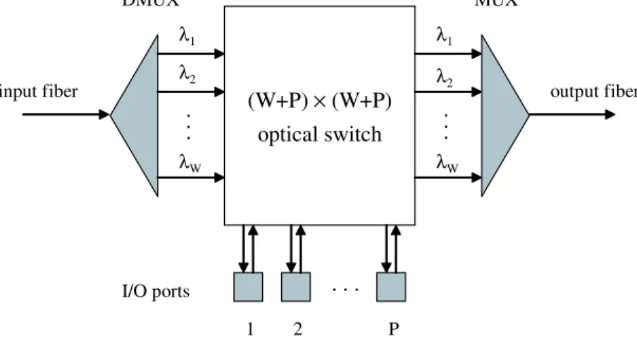
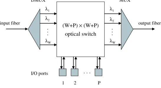
In such situations, the real cost of using large numbers of wavelengths in the network lies not in the fiber but rather in the equipment used to access the fiber. Figure 1-1 illustrates a typical node architecture for a WDM network. Each wave-length, upon arriving at a node, must be demultiplexed from the other wavelengths, switched to the appropriate output port, and then recombined with all other output wavelengths before being retransmitted. Increasing the number of wavelengths being processed at the node increases the number of demultiplexers and filters and the size of the switches required, thereby increasing the cost of the node itself. By developing efficient RWA algorithms that minimize the number of wavelengths, the nodal costs are similarly decreased.
Note that in the previous example, we have implicitly assumed a number of prop-erties for each node, including:
input fiber output fiber (W+P) × (W+P) optical switch λ 1 λ 2 λ W . . . λ 1 λ 2 λ W . . . . . . 1 2 P I/O ports DMUX MUX
Figure 1-1: A typical node architecture for a WDM network.
• Full reconfigurability: All wavelengths arriving at a node are demultiplexed
and actively switched. This allows for the greatest flexibility in wavelength assignment, at the cost of large switch port counts.
• Full accessibility: All wavelengths in the fiber enter the node. This again
increases flexibility of wavelength assignment while increasing processing costs.
• Fine grain switching: All wavelengths are individually switched. Each
wave-length must therefore have its own switch port.
Notice that each property allows for the maximum amount of freedom in routing and wavelength assignment, at the cost of greater processing requirements. In this thesis, we propose to consider relaxing some of the previous assumptions and reducing the complexity of each node. This will have the corresponding effect of introducing additional constraints into the RWA problem, and we will further investigate the impact of these additional constraints and develop new, efficient algorithms for RWA under these conditions. Using this approach, we will develop more cost-effective network architectures and achieve a greater understanding of the tradeoff between complexity and flexibility in a network.
1.1
Fully Flexible Node Architecture
The base case under consideration is where each wavelength is fully processed at each node. In such a scenario, we can consider the figure of merit to be solely the number of wavelengths used. Under these assumptions, we have maximum flexibility in the RWA problem, and hence the performance of an optimal RWA algorithm under these conditions provides us with a bound on the maximum efficiency of wavelength usage. This understanding will also be useful in our subsequent consideration of reduced-complexity node architectures, since it provides a basis for comparison of wavelength efficiency.
There has been considerable work done in the area of finding efficient algorithms for the RWA problem. The literature adopts a number of different approaches to modeling the problem. In the static traffic model, the traffic matrix representing the calls is fixed and does not change over time. In the dynamic traffic model, the traffic matrix is allowed to change over time to represent call arrivals and departures.
In the static model, the objective is typically to minimize the number of wave-lengths, converters, or other cost parameters [28]. This problem was shown to be NP-complete in [8], and thus the literature has focused on the development of heuris-tics and bounds. Other approaches include attempting to maximize throughput for fixed capacity [1], to minimize congestion for a fixed traffic set [19], or to maximize the number of calls supported for a fixed number of wavelengths [27]. However, this approach is limited in that it does not allow dynamic call setup and removals. Additionally, if the traffic is static, nodal connections can be hard-wired to make for “dumb” nodes without reconfigurability, and a flexible node architecture is not required.
The alternative is to use a dynamic model, where calls are allowed to arrive and depart over time. Since we are interested in reconfigurable nodes, we will primarily be interested in this dynamic traffic scenario, where we can use the reconfigurability to accommodate changes in the traffic. One method of modeling call dynamics is to adopt a statistical model for call arrival rates and holding times and design algorithms
to minimize the call blocking probability. Numerous papers have focused on blocking probability analysis under various approximations for simple wavelength assignment algorithms such as the random algorithm [4, 2, 18, 36, 39, 29] and first-fit [17]. How-ever, due to the large state-space size of the problem, the blocking probability of a WDM network for more sophisticated algorithms is extremely difficult to analyze. As a result, most statistical algorithms rely on simplifying approximations and heuristics [21].
An alternative approach considers designing the network to accommodate any traffic matrix from an admissible set. Call arrivals or departures are equivalent to transitioning from one traffic matrix to another. If the transitions can be ac-commodated without rearranging any calls, the RWA algorithm is called wide-sense
non-blocking; algorithms which require call rearrangement are called rearrangeably non-blocking. For example, [14] considers a traffic set such that the maximum load
on each link is bounded by some constant, and attempts to minimize the number of wavelengths used at that given load; [26] works on minimizing the wavelength con-verter usage for networks using a number of wavelengths equal to the maximum link load. Another approach is taken in [24] by admitting any traffic matrix where each node uses at most P ports. It is shown that for the case of a bidirectional ring with
N nodes and P ports, a lower bound of dP N/3e wavelengths is required to support
the worst-case traffic set if no wavelength conversion is employed. Moreover, in [24] a rearrangeably non-blocking RWA algorithm is provided which achieved this bound. An online version based on these ideas was presented in [31] which additionally at-tempts to minimize the number of rearrangements required; this algorithm was later extended from rings to torus networks in [33]. The P -port model is practical since the admissible set is based on actual device limitations in the network. In Chapter 2, we will investigate new rearrangeably non-blocking RWA schemes using the P -port model where wavelength conversion is available.
We will consider a simple yet commonly-used symmetric network architecture, the ring network. We will develop theoretical bounds on the minimum number of wave-lengths required to support rearrageably non-blocking traffic given full wavelength
conversion, and show that a necessary and sufficient number of wavelengths to sup-port P -sup-port traffic in such a network is dP N/4e. We will also show by construction that this bound is achievable using a minimal number of wavelength converters. A second algorithm using fewer converters but more wavelengths will also be given. This chapter will also investigate the issue of the placement of wavelength converters and give lemmas describing how to design to allow arbitrary placement of converters within the network.
1.2
Optical Bypass - Partial Wavelength
Accessi-bility
Chapter 2 considered routing and wavelength assignment, and used total number of wavelengths as the cost metric. This is sensible if all wavelengths are accessed at all nodes – reducing the number of wavelengths therefore reduces the hardware costs as well.
However, in a medium to large network, the amount of traffic (in wavelengths) that each node contributes is typically a small fraction of the total number of wave-lengths in the fiber. It therefore makes sense to consider allowing the majority of the wavelengths entering a node to simply optically bypass the node, and tap only a fraction of the wavelengths that is sufficiently large for adding outgoing calls and re-moving incoming ones. So-called bypass wavelengths then become very inexpensive to manage from a hardware perspective, since they will only be processed at a very lim-ited subset of access nodes. Under this architecture, we impose a limlim-ited-accessibility constraint to the wavelength set (making the RWA problem more complex) in order to reduce overall hardware complexity.
We will refer to banding as the grouping of wavelengths into frequency bands; each band contains multiple adjacent wavelengths. As mentioned, node complexity can be significantly reduced by allowing some bands to completely bypass each node. This is permissible if the RWA algorithm can guarantee that wavelengths within the
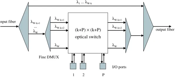
input fiber output fiber (k+P) × (k+P) optical switch λ W-k+1 λ W-k+2 λ W 1 2 P I/O ports λ W-k+1 λ W-k+2 λ W λ 1... λW-k λ W-k+1 ... λ W Coarse DMUX Fine DMUX
Figure 1-2: An OADM architecture with bypass. Note that the switch size depends only on the number of wavelengths k entering the node, not the total number W .
bypassing bands are never dropped at those nodes. For the purposes of the RWA problem, we can group the wavelengths into two bands: a local band, consisting of wavelengths that can be accessed by all nodes, and a bypass band, consisting of wavelengths that can be accessed only by a few designated hub nodes. The bypass band can therefore bypass the majority of the nodes in the network. There are several advantages to a banding approach. One is cost savings. Figure 1-2 shows an optical add-drop multiplexer (OADM) in a system where the total number of wavelengths
W are divided into a local band of k wavelengths and a bypass band of W − k
wavelengths. With banding, only the smaller local band of k wavelengths is switched. Without banding, the switch would have to process all W wavelengths. Another benefit is that the wavelength demultiplexers can be simpler: the first, coarse DMUX need only separate out two large bands, while the second, finer DMUX has a smaller band to work with (only the local wavelengths). Finally, by allowing wavelengths in the bypass band to avoid processing at non-hub nodes altogether, the bypass band can either avoid the switch (thus not suffering power losses due to switching which would reduce the reach of the lightpaths), or be placed in a separate fiber entirely. Such a separate fiber would need to be connected only to the hub nodes and could physically bypass all other nodes entirely.
In Chapter 3, this optical bypass problem is investigated. Specifically, we focus on locally-accessible wavelengths as the primary cost criterion, and determining the minimum number of locally-accessible wavelengths required. Total number of wave-lengths are also a (secondary) consideration, and we investigate architectures that allow the majority of wavelengths to optically bypass most nodes. Three topologies are considered: rings, toruses, and trees.
For rings, we will begin with the results of [30] and Chapter 2 for routing and wavelength assignment with and without converters. We develop a novel approach for banding that minimizes the number of locally-accessible wavelengths, and additionally eliminates the need for switching for all but a designated small number of so-called “hub nodes”.
For toruses, we derive a lower bound on the number of wavelengths required to support P -port traffic, and provide an algorithm which performs favorably compared to this bound. We then extend the banding approach from the ring topology to the torus as well.
For trees, we again derive a lower bound on the number of wavelengths required, and use a ring-embedding approach to develop a low-complexity algorithm that per-forms well compared to this bound. The banding approach is then further extended to the tree topology.
1.3
Multigranularity Switching
In Chapter 4, we propose a second option for reducing hardware costs. Thus far, we have considered only wavelength-level switches. In any reasonably-sized network, the number of wavelengths on the fiber is typically much greater than the nodal degree. The result is that many wavelengths in each input fiber at any given node will be switched to the same output fiber. Rather than switching each wavelength individually, waveband switches can be used to switch all the wavelengths using a single port, instead of requiring a separate port for each wavelength.
wavelengths per fiber is large relative to the number of output fibers, many of the wavelengths will need to be switched between the same fiber pairs. Waveband switch-ing tries to group the wavelengths into wavebands such that all wavelengths in the same waveband can be switched together, allowing the processing to be performed at this coarser waveband level and reducing the number of switches required. With waveband switching each fiber would only be demultiplexed into wavebands, and the number of switches required would equal the number of wavebands. Since the number of wavebands required is typically much smaller than the number of wavelengths, this can greatly reduce the processing and switching costs.
Here we consider the resources of interest to be the number of wavelengths and wavebands required by a given banding algorithm. Reducing the requirement for ei-ther quantity reduces the costs in the network. Conceptually, every banding algorithm can be represented by a point in a two-dimensional performance space, as illustrated in Figure 1-3, indicating the number of wavelengths and wavebands required by the algorithm. The shaded area in the figure represents the achievable region of perfor-mance over all possible algorithms. The goal is to characterize the optimal frontier of achievable performance. This frontier would give the optimal tradeoff between wavelengths and wavebands achievable.
There has been some work in the literature addressing the waveband switching problem. Many papers consider the problem of waveband allocation for static traffic. In [5, 20, 34], integer linear programming formulations are given for a variety of topologies, and the problem of optimal waveband allocation is shown to be NP-complete. In [16], efficient algorithms for dynamic traffic are considered under a simplified traffic model that limits traffic to a single source node and does not allow wavelength overprovisioning, even if it results in fewer wavebands.
In Chapter 4, we propose to consider dynamic traffic under the more general problem of determining the optimal tradeoff between wavelengths and wavebands in band switching. Furthermore, we will allow a more general traffic model where every node is permitted to send traffic into the network. We will first bound the region of achievable performance points by developing lower bounds on the minimum number
wavebands wavelengths min-waveband algorithms min-wavelength algorithms achievable performance region tradeoffs
optimal min-wavelength algorithm optimal
min-waveband algorithm
Figure 1-3: The region of achievable wavelength-waveband tradeoffs.
of wavelengths and the minimum number of wavelengths achievable in any banded system. These bounds are represented by the dotted lines in Figure 1-3.
We next consider two regimes: the minimum-wavelength regime (represented by the horizontal dotted line on the bottom), where we constrain ourselves to con-sider only designs for which the minimum number of wavelengths are used, and the minimum-waveband regime (represented by the vertical dotted line on the left), where we are constrained to designed for which only the minimum number of wavebands are used. We will derive the optimal algorithms in these two regimes, which will correspond to the two points (each lying on one dotted line) closest to the origin that can be practically achieved. We will also present novel algorithms which will achieve a very attractive tradeoff between these two points, demonstrating that points very close to both the minimum number of wavelengths and wavebands can be achieved.
1.4
Hybrid Static-Dynamic Provisioning
Up until this point, we have assumed that each wavelength provisioned in the network has the capability of being dynamically switched in real time. Chapter 2 presents the most relaxed conditions, where all wavelengths were individually switched. However,
even in the next two chapters, each wavelength (including the bypass wavelengths of Chapter 3 and the banded wavelengths of Chapter 4) also has limited switching capability, even if it was not accessible to each node or if it could only be switched together in a band with other wavelengths.
There is an interesting alternate approach to increasing the number of calls the network can support without increasing the number of switch ports required at each node: rather than having all wavelengths be dynamically switched, a number of wavelengths could be statically provisioned. This approach is very sensible for high-traffic networks: in these cases, the high-traffic typically has a large mean and some variation around that mean. If the deviation from the mean is not very large, then it is reasonable to expect that a good approach would be to statically provision a number of wavelengths to support the average behavior of the traffic, and a smaller number of dynamic wavelengths to support the inevitable random variations around this average.
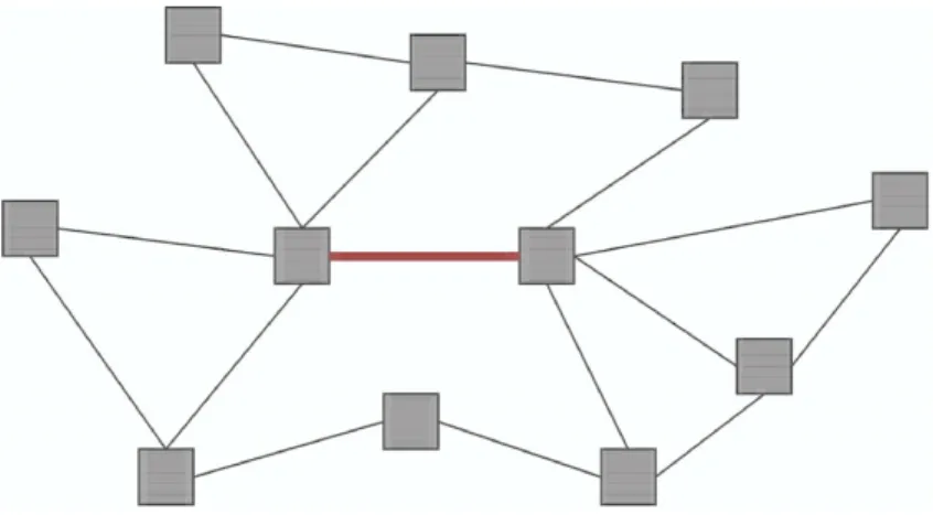
In general, the network can consist of a large number of nodes connected in some arbitrary fashion (see Figure 1-4). This presents a complex provisioning problem over multiple links. For simplicity, in Chapter 5 we will focus on provisioning a single shared link on a backbone network. Figure 1-5 shows a model for the shared colored link in Figure 1-4. We consider provisioning for traffic traveling from left to right along the link. Each wavelength on the link can be used to support one lightpath from one of the incoming fibers on the left side of the link to one of the outgoing fibers on the right side of the link.
Broadly speaking, wavelength provisioning can be done in one of two ways. One option is to statically provision a wavelength by hard-wiring the nodes at the ends of the link to always route the wavelength from a given input fiber to a given output fiber. The advantage to this is that the cost of the hardware required to support static provisioning is relatively low: no switching capability or intelligent decision-making ability is required. The downside is a lack of flexibility in using that wavelength – even if the wavelength is not needed to support a lightpath between the assigned input and output fibers, it cannot be assigned to support a lightpath between any
Figure 1-4: An example of a mesh optical network consisting of numerous nodes and links.
Figure 1-5: A shared-link model based on the colored link in Figure 1-4. The dotted lines denote different users of the link. Since each pair of input-output fibers comprises a different user, and there are 4 input fibers and 4 output fibers, there are a total of 4 · 4 = 16 users in this example.
other pair of fibers.
This shortcoming can be overcome by using dynamic provisioning. A dynamically provisioned wavelength is switched at the nodes on both sides of the link, allowing it to be dynamically assigned to support a lightpath between any source and destination fibers. Furthermore, this assignment can change over time as traffic demands change. This obviously imparts a great deal of additional flexibility. The downside is that the added switching and processing hardware makes it more expensive to dynamically provision wavelengths.
The cost of dynamic provisioning can be somewhat reduced by using waveband switching, as described in the previous section. Under such an approach, wavelengths are grouped into wavebands consisting of several wavelengths each, and all wave-lengths in the same band must be switched together. This provides for limited flexi-bility, since a waveband can still be assigned to any user, but wavelengths within the same band cannot be shared by two different users. Since a single switch port can now accommodate all the wavelengths in a single band, the switch size (and therefore cost) can be greatly reduced.
There has been much investigation of both statically provisioned and dynamically provisioned systems in the literature [2, 4, 7, 14, 18, 21, 27, 28]. Such approaches are well-suited for cases where either the traffic is known a priori and can be statically provisioned, or is extremely unpredictable and needs to be dynamically provisioned. However, in practice, a middle ground is usually more common. Traffic reaching high-bandwidth optical networks typically consists of an amalgamation of a large number of smaller calls, and statistical multiplexing helps reduce the variance of the traffic. As a result, it is common to see traffic demands characterized by a large mean and a small variance around the mean.
A hybrid system is well suited to such a scenario. In a hybrid system, a suffi-cient number of wavelengths are statically provisioned to support the majority of the traffic. Then, on top of this, a smaller number of wavelengths are dynamically pro-visioned to support the inevitable variation in the realized traffic. Such an approach takes advantage of the relative predicability of the traffic by cheaply provisioning the
majority of the wavelengths, but retains sufficient flexibility through the minority of dynamic wavelengths that significant wavelength overprovisioning is not necessary.
We begin by using an asymptotic analysis where we allow the number of users in the system become large, and consider the provisioning requirements in order for the network to be asymptotically non-blocking. We first consider the case where the shared dynamic wavelengths are individually switched, and derive expressions for the amount of static and dynamic provisioning required as a function of the traffic parameters. We then repeat for waveband-switched systems, and show that in a waveband-switched system, provisioning just a small number of switches results in performance very close to a fully switched system.
We finally consider networks with a small, finite number of users. In the fi-nite case, strictly non-blocking performance cannot be achieved using the preceding method. However, in practical networks, we can typically tolerate a fixed probabil-ity of an overflow event (where one or more calls are blocked) occurring. We show how, given a target overflow probability, the results of the asymptotic analysis can be adapted to produce a network whose performance will meet the target require-ments. We also show that by adopting this approach, a relatively small number of additional wavelengths are required (compared to the bound established by the asymptotic analysis).
Chapter 2
Routing and Wavelength
Assignment
The base case under consideration is where each wavelength is fully processed at each node. In such a scenario, we can consider the figure of merit to be solely the number of wavelengths used. Under these assumptions, we have maximum flexibility in the RWA problem, and hence the performance of an optimal RWA algorithm under these conditions provides us with a lower bound on the maximum efficiency of wavelength usage. This understanding will also be useful in our subsequent consideration of reduced-complexity node architectures, since it provides a basis for comparison of wavelength efficiency.
In this chapter, we will investigate a simple yet commonly-used symmetric net-work architecture, the ring netnet-work. We develop theoretical bounds on the minimum number of wavelengths required to support rearrageably non-blocking traffic given full wavelength conversion, and show by construction that this bound is achievable using a minimal number of wavelength converters. Converter placement will also be investigated to determine where converters should be located within the ring, and how to modify a wavelength assignment to accommodate any external restrictions on converter placement.
2.1
System Model
We consider a bidirectional ring with N nodes. Adjacent nodes are connected by two fibers: one supporting wavelengths travelling in the clockwise direction, the other supporting wavelengths in the counterclockwise direction. The two fibers are repre-sented by a single bidirectional link, where each link can support calls travelling in both directions on every wavelength.
A wavelength converter, if available at a given node, can be used to switch a call arriving to that node on one wavelength onto a different wavelength departing the node. If no conversion is employed, a call passing through a node on one wavelength must exit the node on the same wavelength. The cost of providing wavelength con-version from one wavelength to another is assumed to be fixed and independent of the frequency separation between the wavelengths. A traffic matrix or traffic set consists of a set of calls that need to be set up in the network. Each call consists of a source and destination pair. A traffic set is connected if the directed graph corresponding to the set of source-destination pairs is connected. In a single-port network, each node is considered to have a single tunable optical transmitter and receiver. Hence each node may at most originate one call (using any available wavelength) and receive one call (on any wavelength, possibly different from the one used by the transmitter). In a P -port network, each node i has Pi transmitters and receivers, and hence can
transmit and receive Pi different calls. P -port networks can be either symmetric,
where Pi = P for all nodes, or asymmetric, where Pi can differ for each node. This is
a natural problem to consider since equipment constraints limit the number of ports each node has available. The set of all traffic matrices which satisfy the P -port re-quirement is called the admissible set. Routing and assigning wavelengths to each of these traffic matrices is the RWA problem, considered in this chapter.
We consider the problem of supporting any admissible traffic set in a P -port network in a rearrangeably non-blocking fashion. In this context, there are a number of metrics which are relevant to evaluating the performance of a RWA algorithm. One is the worst-case number of wavelengths required by the algorithm – the smaller
the number, the better. Another is the total number of wavelength converters the algorithm uses. Since converters are expensive, an algorithm that uses converters sparingly is preferred. Finally, in general the converter requirements may be different at each node. Certain distributions may be more desirable than others depending on the design criteria: for example, in some cases, we may want a hub design where all converters are placed at a single node; in others we may prefer the converters to be distributed equally at all nodes. We consider algorithms which attempt to design a RWA for these metrics.
In Section 2.2, we derive a lower bound on the number of wavelengths required to support the worst-case traffic set, and present two RWA schemes for both connected and unconnected traffic sets in single-port networks: an optimal algorithm which uses the minimum possible number of wavelengths to support all traffic sets, and a suboptimal algorithm which uses more wavelengths but requires significantly fewer converters. These results are extended to multi-port networks in Section 2.3. In Section 2.4 we develop a method for changing the location of wavelength converters in a given RWA, and apply the method to the algorithms in the previous sections.
2.2
Single-Port Ring Networks
2.2.1
The dN/4e Algorithm For Connected Rings
We consider here the case of a single-port network, and require that the RWA al-gorithm be able to route any connected traffic set in a rearrangeably non-blocking fashion. Our initial goal is to design a RWA algorithm which minimize the number of wavelengths used. The following theorem gives a lower bound on the number of wavelengths required by the worst-case traffic set for this network.
Theorem 1. For a single-port N-node bidirectional ring, at least dN/4e wavelengths
are required by the worst-case traffic set for N even, and d(N − 1)/4e wavelengths for N odd.
network into two sets of N/2 nodes each. Since the nodes were formed in a ring, this cut consists of two links. Consider a traffic set where each of the N/2 nodes in one set wishes to communicate to one of the nodes in the other set. In this case, a total of N/2 calls must cross the cut in either direction, for a total of N calls. Since each link in the cut can support at most two calls on a single wavelength (one clockwise, one counterclockwise), a minimum of dN/4e wavelengths are required to support the calls across the cut. Similar reasoning for N odd gives a bound of d(N − 1)/4e.
It is worth noting that this bound cannot be achieved by a simple routing scheme such as shortest-path. To see this, consider a ring with an even number of nodes N, and number the nodes in increasing order from 1 to N in the clockwise direction. Consider the traffic set where each node ni sends a call to node ni⊕[(N/2)−1]. (We use
⊕ to denote addition modulo N.) Then shortest-path would route all calls in the
clockwise direction, with each call requiring (N/2) − 1 hops to accommodate it. Since there are N calls total, this would require at least N · (N/2 − 1)/N = (N/2) − 1 wavelengths to support it.
We next describe the operation of our first RWA algorithm and assert that it is optimal in the sense that it requires no more than the lower bound of dN/4e wavelengths. The proof follows the description.
Consider an arbitrary connected traffic set {c1, c2, . . . , cN} consisting of
source-destination pairs ci. We term a pair of calls adjacent if the destination node of the
first call is the source node of the second. In a connected traffic set, it is always possible to traverse all calls in the traffic set in adjacent order; i.e., there are no sub-cycles within the traffic set. Therefore without loss of generality we can renumber the calls so that they are indexed in adjacent order; that is, ci is adjacent to ci⊕1 for
every i.
Denote the number of hops required to route a particular call ci in the clockwise
direction by Li. Denote the average number of hops required in the clockwise direction
¯
L =
PN
i=1Li
N
Then the algorithm is as follows: THE dN/4e ALGORITHM
1. TRAFFIC SET PARTITIONING: Let k = min{bN2/4 ¯Lc, N }. Find a set of k
adjacent calls with average clockwise hop length ˜L less than or equal to ¯L. Call
this set the clockwise set. Designate all calls not contained in the clockwise set to be members of the counterclockwise set. (We will shortly show that such sets always exist.)
2. ROUTING: Route all calls in the clockwise set in the clockwise direction. Route all calls in the counterclockwise set in the counterclockwise direction.
3. WAVELENGTH ASSIGNMENT (CLOCKWISE SET): Assign wavelengths to calls using a forward pass and a reverse pass as follows: Index all calls cm in the
clockwise set in adjacent order. Index the wavelengths λn in arbitrary order.
Initialize i = 1 and j = 1.
(a) FORWARD PASS: In this part, beginning with the first call and proceeding in adjacent order, assign as many calls as possible to the first wavelength without using conversion. When a call cannot be fully assigned to the wavelength, assign it entirely to the next wavelength (without conversion) and repeat, until all dN/4e wavelengths are used. This is made explicit below:
i. Assign call ci entirely to λj without using any conversion.
ii. Increment i: i ← i + 1.
iii. If call ci can be assigned entirely to λj without conversion, goto (i).
Otherwise continue. iv. Increment j: j ← j + 1.
(b) REVERSE PASS: In this part, the remaining calls are assigned to the wavelengths in the reverse of the order they were filled in the forward pass, using converters as necessary. More explicitly:
i. Assign as much of the unassigned portion of call ci to λj as possible.
ii. If ci is completely assigned, increment i and goto (i). Otherwise
con-tinue.
iii. Using a wavelength converter, convert the last hop of ci allocated in
(i) from λj to λj−1.
iv. Decrement j: j ← j − 1.
v. If all calls have been assigned, stop. Otherwise goto (i).
4. WAVELENGTH ASSIGNMENT (COUNTERCLOCKWISE SET): Repeat Step 3 with the counterclockwise set in the counterclockwise direction.
We will refer to this as the dN/4e algorithm. The following example illustrates the use of the dN/4e algorithm for a particular traffic set.
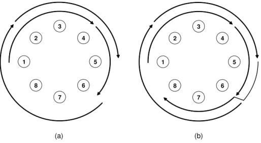
Example 1. Consider an 8-node ring, where dN/4e = 2. Number the nodes from 1
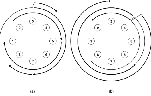
to 8 in the clockwise direction. Consider a traffic set consisting of the following calls, listed in adjacent order: (1,4), (4,6), (6,2), (2,5), (5,8), (8,3), (3,7), and (7,1). We will apply the dN/4e algorithm to this problem.
The average clockwise hop length ¯L = 3, and k = min{bN2/4 ¯Lc, N } = min{b16/3c, 8} =
min{5, 8} = 5. Choose the clockwise set to be the set of calls {(1,4), (4,6), (6,2), (2,5),
(5,8)}, with average hop length ˜L = (3 + 2 + 4 + 3 + 3)/5 = 3 ≤ ¯L. The counter-clockwise set then consists of the remaining calls, {(8,3), (3,7), (7,1)}. Note that the average hop length obeys ˆL = (3 + 4 + 2)/3 ≥ ¯L in the clockwise direction.
In the forward pass on the clockwise set, calls (1,4) and (4,6) are assigned to the first wavelength, while (6,2) and (2,5) are assigned to the second wavelength. This situation is shown in Figure 2-1(a). In the reverse pass, the final call (5,8) is assigned partly on each wavelength and employs a converter at node 6. The final RWA for the clockwise set is shown in Figure 2-1(b).
3 5 7 1 2 4 6 8 3 5 7 1 2 4 6 8 (a) (b)
Figure 2-1: (a) The routing and wavelength assignment of calls in the clockwise set after the forward pass. The inner arrows represent calls on λ1, the outer arrows are
calls on λ2. (b) The complete RWA on the clockwise direction after the backward
pass.
In the forward pass on the counterclockwise set, calls (8,3) and (3,7) are assigned to the first and second wavelengths, respectively. In the reverse pass, (7,1) is assigned partly to both and again requires a converter.
We make two claims regarding this algorithm. First, it is always possible to find a set of k = min{bN2
4 ¯Lc, N} adjacent calls with average clockwise hop length less than
or equal to ¯L. Second, using this algorithm, any admissible traffic set requires at
most dN/4e wavelengths and dN/2e − 2 converters. These claims will be formalized as Lemma 9 and Theorem 2.
Lemma 1. There exists a set of n adjacent calls with average clockwise hop length ˜L less than or equal to the average clockwise hop length of the entire traffic set ¯L, for any 0 ≤ n ≤ N. Furthermore, the N − n calls in the complement of that set have average clockwise hop length ˆL ≥ ¯L.
Proof. We will conduct a proof by contradiction. Suppose there did not exist any set
of n adjacent pairs with average hop length less than ¯L. In particular, this would
1 n · (L1+ ... + Ln) > ¯L 1 n · (L2+ ... + Ln+1) > ¯L · · · 1 n · (LN −n+2+ ... + LN + L1) > ¯L · · · 1 n · (LN + L1+ ... + Ln−1) > ¯L
Summing the entire set of N inequalities, we obtain
L1+ · · · + LN > ¯LN
where the coefficient of each term Li is unity, since each Li is involved in exactly n
of the inequalities and is scaled by a factor of 1
n. Equivalently,
1
N · (L1+ · · · + LN) > ¯L
But since by definition ¯L is the average hop length, this cannot be true. Hence there
must exist a set of n adjacent pairs with average hop length less than ¯L.
The second half of the proof also uses contradiction. Suppose for the remaining
N − n calls, the average clockwise hop length ˆL < ¯L. From the definitions of ˆL and
˜ L, we have that ˆ L = Ln+1+ · · · + LN < (N − n) ¯L ˜ L = L1+ · · · + Ln ≤ n ¯L
Combining the preceding two inequalities and dividing by N, we then obtain
1
which contradicts the definition of ¯L being the average hop length.
For our purposes, we will mainly be interested in applying Lemma 9 for the case of n = k in the proof of the following theorem.
Theorem 2. Given any connected traffic set, the dN/4e algorithm requires only
dN/4e wavelengths and at most dN/2e − 2 converters.
Proof. By Lemma 9, it is always possible for the algorithm to find valid clockwise and
counterclockwise sets. Consider first the clockwise set. For simplicity, consider those cases where the total number of wavelengths N/4 is an integer. (For all other cases, fictitious nodes can be added to increase N/4 to the nearest integer.) First note that
N/4 wavelengths in an N-hop ring can support N2/4 contiguous hops of traffic. By
choice of the clockwise set, the average clockwise hop length in the clockwise direction ˜
L ≤ ¯L. Then the total number of hops required to accommodate the clockwise set,
denoted by DC, is DC = k ˜L ≤ k ¯L ≤ ¹ N2 4 ¯L º · ¯L ≤ N2 4
Since all required hops are contiguous due to the adjacency of all calls in the set, the clockwise set fits in N/4 wavelengths.
Next consider the counterclockwise set, which contains the remaining N − k calls. If k = N, then N −k = 0 and the counterclockwise set is empty and requires no wave-lengths, completing the proof. Therefore assume k = bN2/4Lc. Denote the average
clockwise hop length ˆL; this implies that the average counterclockwise hop length is N − ˆL. Since by Lemma 9 ˆL ≥ ¯L, it must be that the average counterclockwise hop
length N − ˆL ≤ N − ¯L. Denote the total number of contiguous hops required to
DW = (N − k) · (N − ˆL) ≤ (N − k) · (N − ¯L) = µ N − ¹ N2 4 ¯L º¶ · (N − ¯L)
We show in Section 2.6 that for N even, the last quantity is maximized at ¯L = N/2,
giving us DW ≤ µ N − ¹ N2 4 ¯L º¶ · (N − ¯L) ≤ N2 4
which also fits in the dN/4e wavelengths. Note that there is no loss of generality in the assumption of N even, as explained earlier and in Section 2.6.
By construction, the dN/4e algorithm requires up to one converter on each wave-length (except the last) in each direction, for a total of 2dN/4e − 2 converters. Ad-ditionally, consider the location of the converters: each converter, where needed, is located at the destination node of the last call on each wavelength after the forward pass on the clockwise and counterclockwise sets. Since we are dealing with a single-port network, each node is the destination of no more than a single call. This implies that no node requires more than a single converter at most.
Later, in Section 2.4, we will show how the wavelength assignment can be modified to distribute the 2dN/4e−2 converters almost arbitrarily among all nodes in the ring.
2.2.2
The 2dN/7e Algorithm For Connected Rings
Although the dN/4e algorithm achieves the minimum number of wavelengths, it may require as many as 2dN/4e − 2 converters to do so. Since converters may be costly, it is desirable to reduce the number of converters required. In [24] an algorithm is
provided that does not require converters but uses dN/3e wavelengths. Motivated by a desire to find a compromise between these two extremes, we present our next algorithm that requires 2dN/7e wavelengths and only dN/7e converters.
We will begin by restating a result from [24] regarding the routing of adjacent pairs and giving a new lemma on routing adjacent triplets. Then, using these results, we will give an algorithm which divides the connected traffic set into smaller sets of 7 adjacent calls and routes each set of 7 calls onto two wavelengths (in each direction). Lemma 2. Given an adjacent pair of calls, it is possible to fit the calls onto a single
wavelength in either the clockwise or counterclockwise direction with no wavelength conversion.
Proof. See [24].
Lemma 3. Given a direction around the ring and given an adjacent triplet of calls,
if it is not possible to fit the calls into a single wavelength (using no converters) in that direction, then it is possible to fit the calls into two wavelengths (using a single converter) in the opposite direction.
Proof. Denote the calls by their source-destination pairs as follows: (n1, n2), (n2, n3),
and (n3, n4). Without loss of generality, suppose by Lemma 2 that (n1, n2) and
(n2, n3) fit on a single wavelength in the clockwise direction. (If the opposite is true,
then simply reverse the clockwise/counterclockwise directions to follow.) We prove the lemma first for the choice of the clockwise direction, then the counterclockwise.
CLOCKWISE: Suppose the choice of direction was clockwise. If all three calls can be routed in the clockwise direction, then this part of the proof is complete. Suppose they cannot; i.e., part of the path (n3, n4) overlaps part of the path (n1, n2)
in the clockwise direction. This implies that, travelling in a clockwise direction from node n3, we first encounter node n1 before node n4. Reversing the directions, it must
therefore also be the case that travelling in a counterclockwise direction from n3, we
first encounter node n4 before node n1. This is illustrated in Figure 2-2.
We can route (n1, n2) and (n2, n3) each onto separate wavelengths λ1 and λ2 in
n1
n2
n4
n3
Figure 2-2: Beginning at node n3, since we first encounter node n1 before n4 when
travelling in the clockwise direction, we must encounter n4 before n1 when travelling
in the counterclockwise direction.
to n2 free on λ2. Since travelling in the counterclockwise direction we reach node
n4 before n1, the third call (n3, n4) can fit into the free links on λ1 and λ2 in the
counterclockwise direction using a converter at node n2.
COUNTERCLOCKWISE: Next consider if the choice was counterclockwise. It is not possible to fit all calls into a single wavelength in this direction, so therefore we must show it is possible to fit all calls in two wavelengths in the clockwise direction. This is done by noting that since by assumption the first two calls can fit on a single wavelength in the clockwise direction, the third can fit alone on a second wavelength.
Figures 2-3 and 2-4 illustrate examples of applying Lemmas 2 and 3, respectively. We will now use the two preceding lemmas to describe a method for fitting any set of 7 adjacent calls onto at most two wavelengths.
Theorem 3. Given a set of 7 adjacent calls, the entire set can be routed using at
most two wavelengths (in each direction).
Proof. We will provide a proof by construction. Consider the first four adjacent calls.
Divide them into two adjacent pairs. By Lemma 2, each pair can be routed using a single wavelength in either the clockwise or counterclockwise direction. First suppose
3 5 7 1 2 4 6 8 3 5 7 1 2 4 6 8 (a) (b)
Figure 2-3: (a) This adjacent pair cannot be placed on a single wavelength in the clockwise direction. (b) Therefore by Lemma 2, it can fit without converters on a single wavelength in the counterclockwise direction.
3 5 7 1 2 4 6 8 3 5 7 1 2 4 6 8 (a) (b)
Figure 2-4: (a) The adjacent triplet (n1, n4), (n4, n7), (n7, n2) cannot be placed on a
single wavelength in the clockwise direction. (b) Therefore by Lemma 3, it can fit on two wavelengths in the counterclockwise direction using only a single converter. The converter is required at node 4 in this case. Notice also that the triplet can fit using two wavelengths in the clockwise direction.
that the two wavelengths are in different directions. Then they can share the same wavelength, and the first four paths can be routed using a single wavelength. Of the remaining three calls, by Lemma 2 the first adjacent pair can again be fit on a single wavelength in one direction; placing the remaining call on the same wavelength in the opposite direction completes the construction in this case.
Next suppose that the first two pairs can only fit on single wavelengths in the same direction. Without loss of generality, let this direction be clockwise. Consider the remaining adjacent triplet.
If these calls can be placed onto a single wavelength in the clockwise direction, then do so. Also place the first pair on a second wavelength in the clockwise direction. Then place the two calls in the second pair on the same two wavelengths in the counterclockwise direction, each using their own wavelength.
If the last three calls cannot be placed onto a single wavelength in the clockwise direction, then by Lemma 3 they can be placed onto at most two wavelengths in the counterclockwise direction. The first two pairs can then be routed onto the same two wavelengths in the clockwise direction, each pair using its own wavelength.
In general, we can route any connected traffic set by dividing it into adjacent sets of 7 calls and applying the construction in the proof of Theorem 3 to each set. We will call this the 2dN/7e algorithm.
THE 2dN/7e ALGORITHM
1. Divide the traffic set into c = dN/7e adjacent sets of 7, each denoted by Cj,
1 ≤ j ≤ c. Let i = 1.
2. Route each set of 7 calls using 2 wavelengths, following the proof of Theorem 3, for a total of 2dN/7e wavelengths.
Converter Requirements: During the RWA construction, the traffic set is divided into dN/7e sets of 7 adjacent calls; each set of 7 calls uses at most a single converter. Using these facts, we can show that the total number of converters required is upper-bounded by bN/7c.