Design and Control of a Planar Two-Link Manipulator for Educational Use
by David C. Schafer MASSACHUSETTS INSTIUTE OF TECHNOLOGY
SEP
16
2009
LIBRARIES
SUBMITTED TO THE DEPARTMENT OF MECHANICAL ENGINEERING IN PARTIAL FULFILLMENT OF THE REQUIREMENTS FOR THE DEGREE OFBACHELOR OF SCIENCE
ARCHIVES
AT THE
MASSACHUSETTS INSTITUTE OF TECHNOLOGY JUNE 2009
@2009 Massachucsetts Institute of Technology
The author hereby grants to MIT permission to reproduce and distribute publicly paper and electronic copies of this thesis document in whole or in part
in any medium now known or hereafter created
,1A')
Signature of Author:... ... ... ..
Department of Mechanical Engineering
I /1 I A n May 11, 2009 Certifiedby: ...
Accepted by: ...
/
I John LeonardProfessor of Mechanical Engineering jhesis Supervisor
S roessor J. Lienhard V Co s Professor of Mechanical Engineering Chairman, Undergraduate Thesis Committee
//"*
Design and Control of a Planar Two-Link Manipulator for Educational Use
By
David C. Schafer
Submitted to the Department of Mechanical Engineering on May 11, 2009 in Partial Fulfillment of the Requirements for the
Degree of Bachelor of Science in Mechanical Engineering
ABSTRACT
This paper proposes a new robotic planar two-link manipulator design for educational use. Planar two-link manipulators are among the most accessible two-degree-of-freedom robots for students because they function like human arms. As a result they are ideal for laboratory teaching environments.
While previous designs using belt-driven arms served adequately, this new design possesses a number of features that were not possible with the previous design, including more intuitive simplified dynamics, an expanded workspace allowing multiple full rotations, and the ability to be easily reconfigured into an acrobot (an underactuated double-pendulum which can be
stabilized in a vertical configuration while being actuated only at the middle joint).
The governing equations of the system are derived and an analysis of velocity control in the xy plane is perform and a control methodology is also presented by which the arm can be stabilized vertically while in its acrobot configuration. A Discussion of tradeoffs relevant to the future design of similar systems is also presented.
Thesis Supervisor: John Leonard
1. Introduction
This paper proposes a new robotic planar two-link manipulator design for educational use. Planar two-link manipulators are among the most accessible two-degree-of-freedom robots for students because they function like human arms. As a result they are ideal for laboratory
teaching environments.
While previous designs using belt-driven arms served adequately, this new design possesses a number of features that were not possible with the previous design, including more intuitive simplified dynamics, an expanded workspace allowing multiple full rotations, and the ability to be easily reconfigured into an acrobot (an underactuated double-pendulum which can be stabilized in a vertical configuration while being actuated only at the middle joint).
Figure 1: Picture of new manipulator design
Compared to previous belt-driven systems, the motor driving the upper link has been removed from the manipulator's base and mounted on the lower link. The base is placed at the edge of a table and the manipulator is cantilevered over the edge. The lower link is connected to a drive shaft driven by a DC motor mounted on the base. The conversion to the
acrobot configuration is achieved by simply removing the base-mounted DC motor, leaving the system free to rotate around this joint.
2. Design Considerations
The fundamental goal of this research was to design and manufacture a new robotic two-link manipulator for educational use in the Mechanical engineering department. This meant balancing a number of factors in the design process, including cost, manufacturability, simplicity of design, and inclusion of features not present in prior designs.
2.1 Improvements to Prior Art
The new design represents improvements on a number of the shortcomings found in the previous design. The new manipulator features simplified, decoupled dynamics in the xy plane, an expanded workspace, and the ability to simply convert into an acrobot.
2.1.1 Simplified dynamics
The two-link manipulator previously used in the class featured a belt-driven upper arm controlled by a DC motor on the table.
Figure 2: Picture of planar two-link manipulator previously used for the class. Note that the upper link is controlled via a belt drive
This system has the benefit of allowing both motors to be mounted on the base, meaning that the lower arm isn't required to support the weight of the motor controlling the upper arm. However, the belt drive configuration has one unique problem not found in the link-mounted configuration. When the lower link rotates, the upper link experiences a back rotation relative to the lower link equal to the belt drive gear ratio multiplied by the angle rotated by the lower link. For a 1:1 gear ratio, this means that the upper link does not rotate with respect to the ground. For systems where this is not the case, the upper link will rotate with respect to both the ground and the lower link. Avoiding this coupling simplifies the
derivation of the equations of motion for the students, allowing more time in lab to be spent on controlling the system.
a
Figure 3:a) Coupling in belt driven system for r = 1, b) Coupling in belt driven system for 1 < _ < 2, and c) Coupling in belt driven system for 0.5< ! < 1
2.1.2 Workspace expansion
Another problem with the belt driven actuation system is that it limits the work space of the arm to one half rotation. Because the motors are placed on opposite sides of the arm and must both be supported, the table prevents the arm from passing below horizontal. One alternate solution is to place both motors on the same side of the manipulator and extend a
rod from the upper arm to the belt. While this alternate configuration would allow the arm to rotate below horizontal, it cannot accommodate multiple rotations as the belt would wrap around the support for the direct drive motor. Additionally, the tension from the belt acting on the extending rod would cause undesirable torque the manipulator's joints.
These workspace limitations can be avoided by mounting the motor driving the upper arm at the end of the lower arm. As an additional benefit, because there is no contact between the lower arm and the drive shaft of the upper motor, there is less frictional damping between the two surfaces.
Figure 4: Workspaces for a) existing belt-driven manipulator, b) a cantilevered belt-drive manipulator,
and c) the proposed manipulator design
2.1.3 Acrobot Conversion
Another feature of the new design that the previous belt-driven actuator lacked is its ability to operate normally without its bottom motor. In this new design, the lower arm is attached to a drive shaft, which is mounted on two bearings and connected to the drive motor by a set screw. By removing the set screw and dismounting the motor, the arm can rotate around both joints while only being actuated from the upper joint.
Figure 5: Detail of quick detachment mechanism. Set screws in the two rounded ball bearings prevent the shaft from moving in the axial direction, allowing the motor to be detached without compromising the system's ability to rotate.
The ability to easily convert the two-link manipulator to an under-actuated double pendulum (known as an acrobot) provides for the addition of a lab session on control of under-actuated systems.
2.2 Manufacturability
Because the course will require a number of these units for use in its lab section, it is important that they can be easily reproduced. By minimizing part counts and machining operations overall production time for the arm can be decreased.
2.2.1 Integrated Actuation/Sensor Systems
One key element of the motor selection was the decision to use an integrated
motor/gearbox/encoder. While several vendors were considered, including Maxon, which is known for its highly integrated motor designs, a less expensive all-in-one motor was chosen.
2.2.2 Minimizing Part count
The design requires only five machined parts (the base, the drive shaft, two links, and a motor mount). All of these parts (except the shaft) are manufactured from the same /2" aluminum stock. As a result, the vast majority of the machining can be accomplished by cutting a single piece of 18"xl8"x0.5" aluminum stock on a waterjet.
Figure 6: Layout of parts on 18"x18"x.5" aluminum stock
Additionally, because all front-facing holes are clearance holes (for screws, motor shafts, etc.), they can be machined to acceptable tolerances by the waterjet without having to be
undersized and re-drilled after. Performing the majority of the machining operations on the waterjet decreases the machining time for subsequent units (as only a single AutoCAD file is required), meaning that they can be rapidly manufactured for a course.
2.3 Design Trade-offs
As in any design, a number of the decisions were made that involved trade-offs among two or more design criteria. These trade-offs are outlined below to facilitate the future design of similar two-link manipulators.
2.3.1 Solutions to the Wrapping Problem
While the link-mounted motor configuration does eliminate the workspace issues associated with the belt used in previous belt-driven models, it presents a similar problem of its own. Because the link-mounted motor rotates around the drive shaft, any wires connecting to that
motor will become wrapped around the drive shaft when performing multiple rotations. While this problem is not of great concern during most lab exercises-the arm could simply be controlled to move back and forth rather than rotating-it has the potential to cause problems in the acrobot configuration. When performing a swing-up demonstration, in
which the motor slowly adds energy to the system to reach its vertical state, it is easy to provide too much energy to the system, causing it to do multiple rotations in the same direction while trying to reach its stable vertical point.
One possible solution is to mount the motor on the non-table side of the lower link and route a wire outside of the workspace of the arm into the back of the motor. This solution would allow unlimited range of motion for the arm to rotate, but would either require a long,
the wire would add an additional, nonlinear disturbance to the system, making it more difficult to control the arm.
Another solution to the wrapping problem to this problem is to transmit power to the motor through a slip ring mounted concentrically to the lower arm drive shaft. This would
eliminate the wrapping problem, allowing the arm to rotate infinitely in either direction without the need to hold a wire up on the non-table. In many regards, this is the most robust solution, providing full use of the manipulator the smallest risk of damage to the system. Unfortunately, within the context of producing 3-5 units as for a lab class, slip rings proved prohibitively expensive.
Ultimately, a third solution, which matches the cost-effectiveness of the routed wire solution while minimizing the torque effects caused by the tension of the wire. By routing the wires connecting to the link mounted motor through the lower link and providing ample slack in the wire, it is possible to achieve a large number of revolutions without adding a significant input torque or incurring the cost of an expensive rotary connector. For safety reasons, it was important to select a relatively slow motor for this design configuration, allowing ample time to stop the arm before the slack is taken up. Additionally, it is important to attach the wires to the power source through a quick-disconnect terminal, so that if all the slack is taken up by the drive shaft, the motor simply comes unplugged, rather than damaging equipment.
2.3.2 Material Selection
The choice of aluminum for the link material was based predominantly on its machinability. While other materials (acrylic, wood) are cheaper and have better strength/density ratios,
they tend to be more difficult to machine. Meanwhile, compared to other comparably machinable materials, like bronze, aluminum tends to be both cheaper and lighter.
The choice of aluminum over acrylic was also partially influenced by the material selection of the manipulator base. Because the base, both links, and the motor pillow block could easily cut from one piece of aluminum stock, it was substantially more cost effective to use one full aluminum sheet than it would have been to purchase one sheet of aluminum and one sheet of acrylic. For larger batch sizes, acrylic could prove a better choice because its lower density would provide a faster system response.
3. System Dynamics
3.1 Basic model
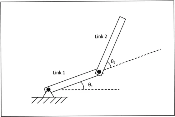
In deriving the system dynamics for this system, the system is defined in terms of the two link angles (and by association, motor angles), shown below. 01 is defined from
horizontal in the fixed reference frame, while 02 is defined in reference to Link 1. Each link is modeled as a uniform rectangular prism and the link-mounted motor is modeled as a uniform cylindrical mass. The masses of various fasteners are neglected due to their limited impact on the dynamics of the system.
Link 2
Figure 7: Schematic of plant with relevant angles defined.
3.2 Velocity control in X-Y plane
As shown in Horn [1] and the position of the endpoint, (Xe, Ye) is given by
(Xe
11 cos 01 11 sin 01 + 12 COS(0 1 +2)+
12
sin(01 +02) (1)'I
This yields a Jacobian of the form Xe = JO
S-l1 sin 01 - 12 sin(01 + 2)
11 cos 81 + 12 cOS(01 + 82)
-2 sin(81 + 2)] [61
12 cos(01 + 82)
]12
(2)
To drive the endpoint along a trajectory x, input joint velocities given by [2]
(3)
Link 1
3.3 Workspace and system singularities
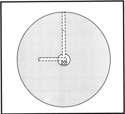
Because neither of the motors are limited in their range, this manipulator has a full 3600 workspace for all achievable endpoint radii (because of the final arm configuration, the upper link is necessarily shorter than the lower arm, meaning that the endpoint can only reach
within 11-12 of the origin).
Figure 8: Workspace for new manipulator design
This system can be driven in any direction(Yi) by moving the motors according to equation (3). For positions where the determinant of the Jacobian is zero and the inverse Jacobian does not exist, no combination of motor velocities can move the endpoint in a given direction and the system is singular [1]. This condition is met for:
[-1, sin 01 -12 sin(01 + 02)](12 cos(01 + 02))
-[1, cos 01 + 12 COS(0 1 + 02)](-12 sin(01 + 02)) = 0 (4)
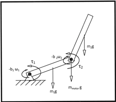
3.4 Balancing Gravity and Equations of Motion
Figure 9: Forces acting on the manipulator
Imposing a torque balance in the static case allows us to find the torques required from the two motors to balance gravity [1]:
MLink1 - ml 1 COS(01) -- mmotorllg COS(0 1) - F12 For the static case where neither, joint is rotating, we find that
F12 = m2g And
T2 = -m 212g cos(0 1 + 02)
+ T1 + -T2
We further find that:
mMLink2
= -22 os(0 1 + 2)+ +2 (8)
For the dynamic case, adapting from Horn, with the addition of damping terms, we find that for rectangular links [1],
m2g -b 2W2 -b1w, mmotor g m1g (5) (6) (7)
( +cos 2 2 + 2 2sin2 (261+6 2)-bO + bz2z
(+ cos ) 2+2 = 2 sin02 -b 262
3.5 State Space Stabilization of Under-Actuated System
Inuoe, et al. [3] derived a state space representation of this system of the form
6 = A6 + BT2
62
(3
(9)
(10)
The result they demonstrated [3] is 0 0 C3C5-C2C4 C32-1C2 C3-C1C2 c C3_ C3
0
10
0
0 01 61 0 3cs 62 c2+c3 -C2 60 + c c C2 2 -C 0 0 ( -c 1-c 2-2c3 -ClC2 c3-C 1C2 (12) Where cl = m1l12 + m212 +1 c2 = m112 + J2 c3 = m2 1 c2 c4 = (mllc1 + m211)9 c5 = m21c29We can control this system by feeding back state information obtained by encoders at the two joints:
For K = (K1
T2 = -K6
K2 K3 K4). This gives us:
0 0 1 0
0
0
0 1
2 C3C5 - C2C4 C3C5 0 0 2 2 2 20 0
3 C - C1C2 C - C1C2 3 C2C4 + C3C4 - C1C5 - C3C5 -C 1C5 - C3C5 0 64 C2 - C1C3
2 c - C1C3o1
22
c2+C3 82-
-_
(K
K2 K3 K4)
(13)
-1 -c2-2c 3By combining the A matrix with the -BK matrix, we find the system's characteristic matrix, whose eigenvalues are the closed loop poles of the system [4]:
6 = (A - BK)6 (14)
By manipulating these gains, it is possible to make the closed loop poles stable. Poles locations can be selected and poles can be placed using a number of techniques, including Ackermann's Method, or using optimal control methods.
4. Conclusion
The proposed two-link manipulator design represents a substantial improvement over previous models. The more intuitive system dynamics will make it easier for students to conceptualize the system. The ability to easily convert the system to an acrobot
configuration provides for the addition of underactuated systems to the lab curriculum. The design is easily manufacturable, with the majority of the parts being waterjetted from a single slab of stock aluminum. Further performance improvements could be made by using faster
motors and using lighter weight materials for the links and performing accurate system identification on the design.
References
1. B.K.P Horn. Kinematics, Statics, and Dynamics of Two-Dimensional Manipulators. MIT AI Laboratory Working Paper 99, 1975.
2. H. Asada, J.-J. E. Slotine. Robotic Analyisis and Control. John Wiley & Sons, Inc., 1986.
3. A. Inoue, M. Deng, S. Hara and T. Henmi. Swing-up and stabilizing control system design for an Acrobot. Proceedings of the IEEE International Conference on Networking,
Sensing, and Control, 2007.
4. N.S. Nise. Control Systems Engineering: Fourth Edition. John Wiley & Sons, Inc. 2004.
5. B.K.P. Horn and H. Inuoe. Kinematics of the MIT-AI-Vicarm Manipulator. MIT AI