Demonstration of Passive Acoustic Detection and
Tracking of Unmanned Underwater Vehicles
by
Kristen Elizabeth Railey
S.B. Mechanical Engineering, Massachusetts Institute of Technology (2013) Submitted to the Department of Mechanical Engineering
in partial fulfillment of the requirements for the degree of Master of Science in Mechanical Engineering
at the
MASSACHUSETTS INSTITUTE OF TECHNOLOGY
and the
WOODS HOLE OCEANOGRAPHIC INSTITUTION June 2018
@ 2018 Kristen Elizabeth Railey. All rights reserved.
The author hereby grants to MIT, WHOI, and The Charles Stark Draper Laboratory, Inc. permission to reproduce and to distribute publicly paper and electronic copies of this thesis
document in whole or in part in any medium now known or hereafter created.
A u th or ... .... ...
Signatu
C ertified by ... Professor Certified by ...Signatu
A The Accepted by...
S ignature r
Chairman, DeparSigna
A ccepted by ...Signature redacted
DN echaical Engineeringre redacted
May 23, 2018 ... Henrik Schmidt of Mechanical and Ocean Engineering Massachusetts Institute of Technology Thesis Supervisorire redacted
Dino Dibiaso Senior Project Leader Charles Stark Draper Laboratory, Inc.
e dacted
i~iisupervisor
... ... Rohan Abeyaratne tment Committee on Graduate Theses Massachjetts)p9f)tute of Technology
ture
redacted
...
Henrik Schmidt Chairman, Joint Commidti'1or App'Iied a Science & Engineering
MASSACHUSETTS INSTITUTE Massachusetts Institute of Technology OF TWoods Hole Oceanographic Institution
JUN 25,2018
LIBRARIES
Demonstration of Passive Acoustic Detection and Tracking of
Unmanned Underwater Vehicles
by
Kristen Elizabeth Railey
Submitted to the Department of Mechanical Engineering
on May 23, 2018, in partial fulfillment of the
requirements for the degree of
Master of Science in Mechanical Engineering
Abstract
In terms of national security, the advancement of unmanned underwater vehicle
(UUV) technology has transformed UUVs from tools for intelligence, surveillance,
and reconnaissance and mine countermeasures to autonomous platforms that can
perform complex tasks like tracking submarines, jamming, and smart mining.
To-day, they play a major role in asymmetric warfare, as UUVs have attributes that are
desirable for less-established navies. They are covert, easy to deploy, low-cost, and
low-risk to personnel. The concern of protecting against UUVs of malicious intent is
that existing defense systems fall short in detecting, tracking, and preventing the
ve-hicles from causing harm. Addressing this gap in technology, this thesis is the first to
demonstrate passively detecting and tracking UUVs in realistic environments strictly
from the vehicle's self-generated noise. This work contributes the first power spectral
density estimate of an underway micro-UUV, field experiments in a pond and river
detecting a UUV with energy thresholding and spectral filters, and field experiments
in a pond and river tracking a UUV using conventional and adaptive beamforming.
The spectral filters resulted in a probability of detection of 96 % and false alarms
of 18 % at a distance of 100 m, with boat traffic in a river environment. Tracking
the vehicle with adaptive beamforming resulted in a 6.2
5.7' absolute difference in
bearing. The principal achievement of this work is to quantify how well a UUV can
be covertly tracked with knowledge of its spectral features. This work can be
imple-mented into existing passive acoustic surveillance systems and be applied to larger
classes of UUVs, which potentially have louder identifying acoustic signatures.
Thesis Supervisor: Henrik Schmidt
Title: Professor of Mechanical and Ocean Engineering Massachusetts Institute of Technology
Thesis Supervisor: Dino Dibiaso Title: Senior Project Leader
Acknowledgments
Most of all, I would like to thank Henrik Schmidt for his support of me as a researcher and student. Thank you for all your advice on my thesis and coursework. Also thank you for advocating for me and believing in me as a researcher.
I would also like to thank my co-supervisor, Dino DiBiaso, for his support and guidance - not only on my thesis research but also for my experience at Draper Labs. Thank you for
all your feedback and encouragement.
Next I would like to thank all of my colleagues in the Laboratory of Autonomous Marine Sensing Systems - especially Mike Benjamin, Misha Novitzky, Caileigh Fitzgerald, Paul Robinette, Eeshan Bhatt, Rui Chen, Oscar Viquez, Nick Rypkema, Greg Nannig, and Erin Fischell. Thank you for your support, guidance, and friendship.
I'd also like to recognize Joe Edwards, Nick Pulsone, and Doug Hart for their mentorship
while at MIT as an undergrad and at MIT Lincoln Laboratory. You inspired me to pursue my master's degree in mechanical engineering, specializing in ocean robotics.
Finally I want to thank my friends and family, especially my parents - Cheryl and Malcolm - and my brothers - Owen and Stuart - for always being there for me. I could not have accomplished this without you. And thank you to Derek, for being my best friend and support system.
To make this research possible, I am grateful for the support from the National De-fense Science and Engineering Graduate Fellowship and Draper Labs Fellowship, as well as DARPA for the support of the Bluefin Sandshark unmanned underwater vehicle.
This research was conducted with Government support under and awarded by DoD, Air Force Office of Scientific Research, National Defense Science and Engineering Graduate
Contents
1 Introduction
2 Background
2.1 Current State of Technology and Vulnerabilities in UUVs 2.1.1 Hull and Propulsion Design . . . .
2.1.2 Stability . . . . 2.1.3 Energy . . . . 2.1.4 Autonomy . . . . 2.1.5 Communication . . . . 2.1.6 Sensors . . . . 2.1.7 Navigation . . . . 2.2 Applications of UUVs . . . . 2.2.1 Current Missions . . . . 2.2.2 Future Missions . . . .
2.3 Motivation for Detecting and Tracking UUVs
2.3.1 U .S. Navy . . . . 2.3.2 DARPA . . . .
2.3.3 Rapid Reaction Technology Office . .
2.3.4 Defense Science Board . . . .
3 Related Work
3.1 Acoustic Spectrum Analysis of UUVs . . . . .
3.2 Automatic Target Recognition . . . .
3.2.1 Detection with Active Sonar . . . .
3.2.2 Detection with Passive Sonar . . . . .
. . . . 2 4 . . . . 2 5 . . . . 2 6 . . . . 2 7 . . . . 2 8 . . . . 2 9 . . . . 3 0 . . . . 3 1 . . . 3 2 . . . . 3 2 . . . 3 3 . . . . 34 . . . 34 . . . 35 . . . 35 37 37 38 39 39 19 23 23
3.3 Passive Acoustic Tracking . . . .
4 Detection and Tracking Theory
4.1 Detection Threshold Theory . . . .
4.1.1 Passive Sonar Equation . . . . 4.1.2 Receiver Operating Characteristic Curves . . . .
4.2 Power Spectral Density . . . . 4.3 Underway Vehicle Detection . . . . 4.3.1 Short-Time Fourier Transform . . . . 4.3.2 Energy Calculation . . . . 4.3.3 Spectral Filters . . . . 4.3.4 Sum m ary . . . . 4.4 Beamform ing . . . . 4.4.1 Uniform Linear Arrays . . . . 4.4.2 Weighted Linear Arrays . . . . 4.4.3 Array Steering . . . .
4.4.4 Beamforming on a Moving Target . . . . 4.4.5 Minimum Power Distortionless Response (MPDR)
5 Experimental Methods
5.1 Bluefin Sandshark UUV . . . .
5.1.1 Tetrahedral Array . . . . 5.1.2 Autonomy - MOOS-IvP . . . .
5.2 Horizontal Line Array . . . .
5.3 Power Spectral Density Estimate - Test Setup . . . . 5.4 Jenkins Pond Demonstration - Test Setup . . . .
5.5 Charles River Demonstration - Test Setup . . . .
6 Field Experiments and Results
6.1 Power Spectral Density Estimate - Results . . . .
6.2 Jenkins Pond Demonstration - Results . . . .
6.2.1 D etection . . . . 6.2.2 Tracking . . . . Beamformer . . . . 8 43 43 43 44 45 46 46 46 47 48 49 49 54 55 57 58 61 61 62 63 64 64 65 67 73 73 75 75 76 . 40
6.3 Charles River Demonstration - Results . . . . 80 6.3.1 Detection . . . 81
6.3.2 Tracking . . . 84
List of Figures
2-1 Bluefin Robotics line of UUVs: Bluefin Robotics, a major manufacturer of
UUVs, produces a range of UUVs that vary by depth rating, which relates to
the size of the vehicle. The Hovering AUV (HAUV) is the only vehicle they manufacturer that does not have a torpedo-shaped hull and single propeller d esign [11 . . . 25
4-1 Windowing effect on incoming signal x(t): when a window function, w(t), is
applied to the signal, the signal becomes segmented, which is used for short-tim e Fourier transform
[55].
. . . 474-2 Frequency response of ideal low pass filter: frequencies that are passed through are between positive and negative w, frequencies that are eliminated are rep-resented by the stop-band [781. . . . 47
4-3 Process for producing ROC curves on a moving target: incoming data from a hydrophone element is analyzed by applying short-time Fourier transform, spectral filtering, and energy thresholding. The result is compared to the true presence of the UUV to calculate probabilities of false alarms and true detections. . . . . 49 4-4 Coordinate system for beamforming: elevation and azimuth are defined as 0
and
#
respectively. . . . . 504-5 Coordinates and element spacing of a line array: a vertical line array measures direction of arrival in elevation, or 0. The elements, which are identified by numbers 0 to N are evenly spaced by Az
[94].
. . . 504-6 Filtering process of an array in visual form: the incoming signal on each element of the array
f(t,
p,) is filtered by h(r) and summed together to produce the array output y(t) [94]. . . . 514-7 Delay and sum beamforming process in visual form: the signal on each ele-ment of the array,
f(t
-r), is filtered by applying a delay, h, (r), and summed together to produce the array output y(t) [94]. . . . .. 534-8 Weights for a narrowband beamformer: gain and phase can be modified to create an optimal beamformer
[94].
. . . . 534-9 Comparison of Kaiser and uniform weights: the tradeoff between Kaiser and uniform weights is side lobe height and beamwidth. Kaiser weighting de-creases side lobe heights but widens the beamwidth [94]. . . . 55 4-10 Theoretical beampatterns of Charles River array configuration: in each
sub-plot, uniform (blue) and Kaiser (red) weightings are compared. The top figures are beampatterns at 10,000 Hz, the cutoff frequency for spatial alias-ing in this configuration. The bottom figures are beampatterns at 5,000 Hz, half of the cutoff frequency for spatial aliasing. The left plots are steered to broadside or 90", the right plots are steered to 1350. . . . . 56
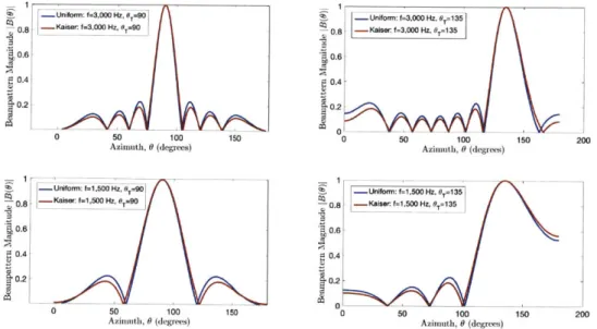
4-11 Theoretical beampatterns of Jenkins Pond array configuration: in each sub-plot, uniform (blue) and Kaiser (red) weightings are compared. The top figures are beampatterns at 3,000 Hz, the cutoff frequency for spatial alias-ing in this configuration. The bottom figures are beampatterns at 1,500 Hz, half of the cutoff frequency for spatial aliasing. The left plots are steered to broadside or 90', the right plots are steered to 135.. . . . . 57
4-12 Beamforming process for a moving target: to estimate bearing of a moving target, the incoming signal on each array element is segmented into time snap-shots, discrete Fourier transform is applied, and frequencies are individually beamformed. The beamformer results across all frequencies are averaged, resulting in a beamformer output over time. . . . . 58
5-1 Bluefin Sandshark micro-UUV: this micro-UUV manufactured by Bluefin Robotics was used to demonstrate passive detection and tracking in a pond and river experim ent
[73].
. . . . 61 5-2 Tetrahedral array in nose payload section of the Bluefin Sandshark micro-UUV. 635-3 Element configuration of a tetrahedral array: a tetrahedral array is in the nose payload section of the micro-UUV, which was used to collect acoustic data for the PSD estimate of the vehicle. . . . . 63
5-4 Hydrophone element HTI-96-MIN: this hydrophone was used to measure the power spectral density estimate of the micro-UUV. Four of the hydrophones are configured in a tetrahedral array in the nose of the Bluefin Sandshark micro-UUV used in these experiments
[6].
. . . . 645-5 Autonomy decision-making process of MOOS-IvP software: MOOS-IvP is configured such that the vehicle computer is separate from the autonomy payload [5]. . . . . 64
5-6 Diagram of the horizontal line array and data acquisition setup: data from the horizontal line array was collected using an analog to digital converter, data storage unit, GPS trigger, and power . . . . . . . 65 5-7 Power spectral density estimate experiment at the MIT alumni pool: the
Bluefin Sandshark micro-UUV was secured while its propellor revolved at approximately 1.5 m/s. The onboard acoustic sensors collected acoustic noise d ata . . . . 66 5-8 Satellite image of Jenkins Pond: array was bottom mounted about 10 m off
shore and the vehicle followed a loiter behavior about 100 m off shore. . . . . 67 5-9 Shore launch of vehicle at Jenkins pond: the UUV was launched from the
shore and the array was bottom mounted about 10 m from the shoreline. . . . 68 5-10 UUV track in X-Y coordinates over time at the Jenkins Pond experiment:
UUV performed a loiter pattern about 100 m offshore. The progression of
time is represented by the colorbar and the total mission time was about 20 min. Navigation data was taken from the vehicle's inertial navigation system. 68
5-11 UUV depth over time at the Jenkins Pond experiment: depth data was taken
from vehicle's inertial navigation system. The short periods of zero-depth are the vehicle surfacing for a GPS fix. . . . 69
5-12
UUV speed over time at the Jenkins Pond experiment: speed data was takenfrom vehicle's inertial navigation system. The short periods of zero-speed are the vehicle surfacing for a GPS fix. . . . . 69
5-13 Satellite image of the Charles River: the horizontal line array was mounted
on the MIT Sailing Pavilion dock and the vehicle followed a loiter behavior about 100 m off shore. . . . . 70
5-14 UUV was launched from the MIT Sailing Pavilion dock at the Charles River and the array was mounted to the dock. . . . 70
5-15 UUV track in X-Y coordinates over time at the Charles River experiment: UUV performed a loiter pattern about 100 m offshore. The progression of time
is represented by the colorbar and the total mission time was about 20 min. Navigation data was taken from the vehicle's inertial navigation system. . . . 71 5-16 UUV depth over time at the Charles River experiment: depth data was taken
from vehicle's inertial navigation system. The short periods of zero-depth are the vehicle surfacing for a GPS fix. . . . . 72 5-17 UUV speed over time at the Charles River experiment: speed data was taken
from vehicle's inertial navigation system. The short periods of zero-speed are the vehicle surfacing for a GPS fix. . . . 72
6-1 Spectrogram of the power spectral density estimate experiment at the MIT alumni pool: the spectrogram shows how frequencies change over time in a visual representation. The vehicle exhibited strong frequencies between
16kHz and 18kHz. ... .. ... 73
6-2 Power spectral density estimate of Bluefin Sandshark micro-UUV: the power spectral density estimate was derived from acoustic data collected on-board the vehicle. The data was collected in a pool environment. The standard deviation of the data was used as the error margin. . . . . 74
6-3 Spectrogram of the Jenkins Pond experiment: the spectrogram shows how frequencies change over time in a visual representation. The vehicle is identi-fiable by its strong frequency tone at 800 Hz, which is aliased down from the true frequency of 20 kHz. The vehicle enters the water at around 800 s. . . . 76
6-4 ROC curves from the Jenkins Pond experiment: the bandpass filter applied to the aliased frequency of 800 Hz outperforms no filter applied to the data. . 77
6-5 Area under the ROC curves of the Jenkins Pond experiment: the area under the curve is a measure of the ROC curve performance. The bandpass filter increases the area under the curve by about 10%. . . . 78
6-6 Conventional beamforming results of the Jenkins Pond experiment: the true vehicle track is the triangular pattern shown in the beamformer. There is a broadband interferer at 90 . . . . 78
6-7 Estimated versus expected bearing of the UUV at the Jenkins Pond
experi-ment with conventional beamforming. . . . 79 6-8 Absolute difference, or error, between the estimated and expected bearing
of the vehicle over time at the Jenkins Pond experiment with conventional beam form ing . . . 80
6-9 MPDR beamforming results of Jenkins Pond experiment: the vehicle true vehicle track is the triangular pattern shown in the beamformer. There is a broadband interferer at 90 . . . 80
6-10 Estimated versus expected bearing of the UUV at the Jenkins Pond
experi-ment with MPDR beamforming. . . . 81 6-11 Absolute difference, or error, between the estimated and expected bearing of
the vehicle over time at the Jenkins Pond experiment with MPDR beamforming. 82
6-12 Spectrogram of the Charles River experiment: the spectrogram shows how
frequencies change over time in a visual representation. The vehicle is iden-tifiable by its strong frequency tone at 17500 Hz, which is aliased down from the true frequency of 20 kHz. The vehicle enters the water at around 300 s. . . 82
6-13 ROC curves from the Charles River experiment: three different filters were
applied to the dataset to increase the SNR of the vehicle signature. The first filter was a bandpass filter from 16 kHz to 18 kHz. The second filter was the
PSD estimate as a frequency shaping filter. Finally, the third filter was a
combination of the bandpass filter and the PSD filter. The combination of the bandpass filter and PSD filter outperformed the other spectral filters. No filter applied, represented in red, performed the worst. . . . 83
6-14 Area under the ROC curves of the Charles River experiment: the area under the curve is a measure of the ROC curve performance. The PSD and bandpass filter combination increases the area under the curve by about 10% from no filter applied . . . . 84
6-15 Conventional beamforming results of the Charles River experiment: the true
vehicle track is the triangular pattern shown in the beamformer . . . . . 85 6-16 Estimated versus expected bearing of the UUV at the Charles River
experi-ment with conventional beamforming. . . . ... 85 6-17 Absolute difference, or error, between the estimated and expected bearing
of the vehicle over time at the Charles River experiment with conventional beam form ing . . . 86
6-18 MPDR beamforming results of Charles River experiment: the true vehicle
track is the triangular pattern shown in the beamformer. . . . 86
6-19 Estimated versus expected bearing of the UUV at the Charles River
experi-ment with MPDR beamforming. . . . 87 6-20 Absolute difference, or error, between the estimated and expected bearing of
the vehicle over time at the Charles River experiment with MPDR beamforming. 87
List of Tables
2.1 Summary of UUV size classes: UUVs are categorized by their size, which is correlated to endurance and payload size [12]. . . . 24
4.1 Detection algorithm decisions and probability definitions: the result of the detection algorithm will either be a correct detection, false alarm, missed detection, or correct no detection. . . . 44 4.2 Array specifications used in the Jenkins Pond and Charles River experiments:
the Jenkins Pond array had a wider aperture than the Charles River array due to the increase in the number of elements and element spacing; however, it had lower cutoff frequency for spatial aliasing. . . . . 56 5.1 Bluefin Sandshark micro-UUV dimensions and performance specifications:
the micro-UUV is a man-portable platform and a member of the smallest class of U U Vs [73]. . . . . 62 6.1 Probability of detection and false alarms from the ideal detection threshold
for the Jenkins Pond experiment. The bandpass filter was applied to the aliased frequency of 800 Hz. . . . 76
6.2 Comparison of absolute angle difference, or error, between conventional and MPDR beamforming at the Jenkins Pond experiment . . . 79
6.3 Probability of detection and false alarms from the ideal detection threshold for the Charles River experiment. The bandpass and PSD filter combination had the best performance. . . . 83 6.4 Comparison of absolute angle difference, or error, between conventional and
Chapter 1
Introduction
Due to their growing technical maturity, unmanned underwater vehicles (UUVs) are now considered valuable assets to multiple industries: defense, oil and gas, environmental moni-toring, and salvage. Today, UUVs take on missions that were previously considered impossi-ble with traditional maritime platforms such as ships, divers, and submarines. For example, UUVs are capable of tracking plumes [79], following submarines [36], detecting mines
[46],
and collecting environmental data under ice[191-
all missions that were once too "dull, dirty, and dangerous" to complete[87].
From advancing technology in sensing, autonomy, and communication, UUVs have over-come some of the most challenging aspects of working in an ocean environment. For instance, improving artificial intelligence has enabled UUVs to perform longer missions without hu-man supervision, such as adapting to the ocean environment to search for submarines
[54].
In addition, UUVs have benefited from improved energy storage and small size, weight, and power (SWAP) sensors.However, with new capabilities come new threats. In terms of national security, UUVs are now useful tools for tracking submarines
[57],
invading harbors[49],
and collecting oceano-graphic data in restricted areas[13].
They are desirable for their covertness, ability to navigate shallow waters, and multiplication of force. Some classes of UUVs are viewed as disposable assets because of their low cost [61]. To rise to the challenge, the U.S. Department of Defense has published multiple calls for proposals to detect and track UUVs. DARPA requested an "Open Ocean Counter Unmanned Underwater Vehicle (OOCUUV) Study"innovation research (SBIR) for "Unmanned Undersea Vehicle (UUV) Detection and Classi-fication in Harbor Environments" [4], and the U.S. Department of the Navy has requested a "Counter-Unmanned Undersea Vehicle (C-UUV) Capability Demonstration for the Stiletto Maritime Demonstration Program" [2].
The motivation of this thesis stems from the urgent demand for counter-UUV technology. This thesis is the first demonstration of passively detecting and tracking an autonomous underwater vehicle strictly from its self-generated noise. The contributions include:
1. Analysis of the frequency spectrum of a micro-UUV's self-generated noise
2. Field experiments in a pond and river quantifying the detection and false alarm rates of a UUV with different spectral filters
3. Field experiments in a pond and river demonstrating tracking a UUV using
conven-tional and adaptive beamforming on a horizontal line array.
The work from this thesis answers one of the many critical questions to the counter-UUV problem: how well can a UUV be passively detected and tracked using acoustics in a realistic environment?
This thesis begins with an overview of what UUVs are and what they are used for. This general background sets the stage for why counter-UUV technology is important and how it can be accomplished. This thesis demonstrates how the electro-mechanical noise generated
by the UUV is a vulnerability - that it can be used to detect and track UUVs with passive acoustics.
The next chapter describes work related to detecting and tracking UUVs with passive sonar. This chapter includes the current studies of UUV's acoustic noise as well as existing passive tracking systems for maritime applications.
Following the background and related work, the fourth chapter, on detection and tracking theory, illustrates the technical concepts and derivations for finding UUVs with passive acoustics.
In the fifth chapter, experimental methods are described, including the array configura-tion, robot specifications, and test bed descriptions. The sixth chapter is on field experi-ments and results, summarizing three experiexperi-ments: power spectral density estimate and two demonstrations of passive detection and tracking.
Finally, the concluding chapter is a synopsis of the relevant results, implications of this work for the field, and next steps.
Chapter 2
Background
2.1
Current State of Technology and Vulnerabilities
in UUVs
The purpose of this section is to give a short overview of UUV subsystems to show what electro-mechanical systems could cause acoustic noise, allowing the vehicle to be detected and tracked passively. In addition, this section emphasizes how common the subsystems are to all classes of UUVs. Because they share these subsystems, UUVs will potentially have similar causes of acoustic noise. Consequently, the demonstration of passively detecting and tracking UUVs done with the Bluefin Sandshark micro-UUV in this thesis could be representative of other UUVs, particularly UUVs optimized for endurance with a single propeller and minimal appendages.
Autonomous underwater vehicles are defined as being unmanned, untethered, and self-propelled [16]
[27].
On-board, they carry actuators, sensors and intelligence to complete missions without guidance of a human operator [16].UUV design is influenced by application; therefore, UUVs range dramatically in size and
speed, as well as in depth rating
[16] [27].
For example, UUVs for mine countermeasures operate in shallow waters so they require a depth rating of only 200 m [16] [18]. On the otherhand, vehicles for deep-sea surveys for marine geology, such as in the oil and gas industries, have a depth rating of 3000 - 6000 m [16] [99]. A UUV can be between 5 kg and 9000 kg, and
a UUV is a torpedo-shaped hull with a propeller and fins for control [16] [991.
Being autonomous, the vehicle can handle its own dynamic control, such as ballasting, pitch, and roll, as well as its mission control [16]. The vehicle has an onboard computer(s) to handle the decision-making [16]. In some cases, acoustic communication is available so a human operator can provide some guidance such as mission control [16].
The sensors on UUVs vary by mission and can include sonar for bathymetry and con-ductivity, temperature, and depth (CTD) measurements for water column analysis [16] [99]
[47].
In more detail, the UUV subsystems can be broken down into: hull design, propulsion, stability, energy, autonomy, communication, sensors, and navigation.
2.1.1
Hull and Propulsion Design
One approach to dividing up UUVs into classes is based on size and weight: man-portable, lightweight, and heavyweight [971. Below, Table 2.1, summarizes the different classes of vehicles.
Class Diameter [in] Displacement Endurance, Endurance, Payload [ft3]
[lbs] High Hotel Low Hotel Load [hours] Load [hours]
Man- 3-9 < 100 < 10 10-20 < 0.25
portable
Lightweight 12.75 ~ 500 10-20 20-40 1-3
Heavyweight 21 < 3,000 20-50 40-80 4-6
Large > 36 ~ 20,000 100-300 > 400 15-30
Table 2.1: Summary of UUV size classes: UUVs are categorized by their size, which is correlated to endurance and payload size [12].
Across all of these size categories, the hydrodynamics and propulsion systems of UUVs are designed around application. A vehicle optimized for endurance has a streamlined hull, few appendages, and an efficient, single propeller [16]. The propeller is usually driven by a brushless DC current motor for its high efficiency [12]. Vehicles that are designed with station-keeping in mind, not long distances, use many thrusters to maneuver the vehicle vertically and laterally [12].
For the common navy applications of intelligence, surveillance, and reconnaissance, and mine countermeasures, UUVs are designed for long endurance. For example, all vehicles
in the Bluefin Robotics line of UUVs, pictured in Figure 2-1, share this optimized design: minimal appendages, tube-shaped, and single propeller.
Outside of the common torpedo-shaped hull design with single propeller, flapping-fin propulsion has been researched for enabling highly maneuverable underwater vehicles [15]. Reverse engineering fish propulsion is inspired by the fact that swimming animals are adept at maneuvering and sensing an underwater world [15]. Bandyopadhyay gives an overview of mature bio-inspired robots, many of which are from the Naval Undersea Warfare Center.
The electromechanical propulsion system of UUVs is a major source of acoustic noise. The cavitation caused by the propeller creates broadband noise that could be used to not only identify the vehicle, but also track it.
60 M
200 M
1500 M
Figure 2-1: Bluefin Robotics line of UUVs: Bluefin Robotics, a major manufacturer of UUVs, produces a range of UUVs that vary by depth rating, which relates to the size of the vehicle. The Hovering AUV (HAUV) is the only vehicle they manufacturer that does not have a torpedo-shaped hull and single propeller design [1].
2.1.2
Stability
Speed and endurance are a trade-off to stability in UUVs [12]. UUVs with fine control for maneuvering have many thrusters to station-keep. Although they can adeptly maneuver, they do not have the endurance of torpedo-shaped, single propeller UUVs [16]. Vehicles without multiple thrusters rely on fins to change the direction of their movements.
The fins and additional thrusters to stabilize and control the vehicle generate unwanted acoustic noise like the propulsion system. This can be used to further identify the vehicle
with passive acoustics.
All UUVs are equipped with a ballast system that is either fixed or variable [12].
Un-derway, the ballast keeps the UUV neutrally buoyant 112]. During emergencies, the vehicle has a drop weight so it can immediately surface [12]. Stabilizing the UUV on the surface is particularly difficult due to waves, as is having the vehicle dive from the surface [121.
During deployment, UUVs frequently resurface to receive a GPS fix to aid navigation underwater. Due to the difficulty of diving, UUVs will spend an unavoidable, large amount of time on the surface, making them vulnerable to being sighted.
Triantafyllou et al. are a comprehensive review of underwater vehicle maneuvering and control, covering the topics of propellers and propulsion, hydrodynamic forces on the vehicle, and transfer functions and stability [951.
2.1.3
Energy
Due to the limitation of being underwater, autonomous underwater vehicles are battery-powered. The UUV requires power for endurance, speed, and sensors
[12].
AUVSI RANDreported that the technology behind propulsion power and energy is the second most chal-lenging aspect of UUV research, behind autonomy [12]. To emphasize the shortcomings of energy in UUVs, a heavyweight vehicle class with a low hotel load has an endurance of only three days [12].
In the 1980s lead-acid batteries were commonly used in UUVs but they have low en-ergy given their weight. The primary enen-ergy source found in today's UUVs is lithium ion secondary batteries [75] [58]. Hasvold et al. give a comparison of typical electrochemical power sources in UUVs - comparing aspects like energy density, cost, and rechargeability. For integrating batteries into UUVs, Bradley et al. examine problems with operating at different temperatures, combining individual cells, battery monitoring, and charging and discharging, as well as the trade-offs of power, speed, and range
[18].
A future replacement for the energy source in UUVs could be fuel cell power systems [75]
[12].
Mendez et al. give an overview of fuel cells for UUVs, which have higher specific energy than batteries.26
-2.1.4
Autonomy
A definition of decision autonomy is to "sense, interpret and act upon unforeseen changes
in the environment and the UUV itself" [56]. According to AUVSI RAND, autonomy is considered to be the greatest long-term challenge of the development of UUVs
[12].
Espe-cially for long missions, the UUV needs to be able to sustain itself and recuperate from any malfunctions[56].
This could mean changing its mission, for example re-planning its path if it expects to run out of energy[56].
At a high level, there are two autonomy architectures: sense-plan-act and reactive. Sense-plan-act is one method of the control architecture of the vehicle's sensors and actuators
[56].
This system tries to accurately model the environment around it from sensor input and act on the model
[56].
Modeling the ocean accurately on a small temporal and spatial scale on-board a UUV is challenging, however. Accurate ocean modeling requires various types of data, lots of computing power, and historical statistics. For example, an ocean modeling system, HYCOM, outputs daily predictions at the Navy DoD Supercomputing Resource Center [7].On the other hand, reactive control architectures do not plan but rather "react" to the world around them
[56].
An autonomy mission example of this would be to transit to a waypoint, gather bathymetric data, and avoid collisions[56].
The resulting action as the vehicle progresses would depend on the environment in the moment[56].
The challenge of working in an ocean environment is that it is constantly changing. It is difficult to model the ocean environment onboard a UUV with precision and accuracy. In addition, defining autonomous behaviors for every possible scenario is a demanding -indeed, impossible - requirement.
Despite the daunting challenge of working in the ocean autonomously, artificial intelli-gence in UUVs has made great strides. Marine autonomy has evolved past following way-points for surveying to highly complex missions, including coordinated swarms that can perform optimal time path planning on dynamic ocean flows
[69].
Marine Robot Autonomyis an up-to-date and extensive overview of autonomy for underwater robots, covering archi-tectures such as MOOS-IvP; limitations to achieving true autonomy like underwater nav-igation; and specific algorithms, including simultaneous localization and mapping (SLAM) [85].
Coordinating a fleet of autonomous mobile marine platforms is an important area of research, since having multiple robots would make it possible to cover large areas of the ocean over long amounts of time. The advanced autonomy architecture required to control a collaborative network of vehicles goes beyond behavior-based autonomy. Henrik et al. describe how the nested autonomy paradigm, with its core feature of integrated sensing, modeling, and control, is key to multi-vehicle missions [83]. With nested autonomy, each vehicle is capable of detecting, classifying, localizing, and tracking an ocean event of interest, like a subsea volcanic plume
[83].
Henrik et al. discuss examples of nested autonomy in field experiments, including adaptive thermocline tracking and bistatic target tracking [83]. These experiments involved up to seven UUVs, equipped with underwater acoustic communication modules[83].
The software was implemented using MOOS-IvP, an open-source behavior-based, autonomous command and control architecture [83].Other examples of multi-vehicle coordination and advanced autonomy are using coop-erative gliders for environmental monitoring discussed in Leonard, and time-optimal path planning for swarms of vehicles that can account for uncertain, three-dimensional, and dy-namic flow fields with constraints such as forbidden regions [66] [67]. Ehlers et al. give an overview of the autonomy framework needed for cooperative vehicle target tracking
[38].
Another important aspect of autonomy - risk management - is evaluated in Brito et al. Assessment of risk is needed for true autonomy, as vehicles and their stakeholders need to understand the consequences of certain decisions in a dynamic and unstructured environment like the ocean [21]. The authors discuss risk of loss, collision, failure and more [21].
2.1.5
Communication
UUVs have a communication suite that operates differently when the vehicle is underway and on the surface. Above water, UUVs rely on a mast with antennas of electromagnetic sensors to communicate [12]. On the mast, the UUV usually has a configuration of Wi-Fi,
GPS, and satellite communication. Underwater, electromagnetic waves attenuate. As a
consequence, UUVs predominately use acoustic communication such as the WHOI Micro Modem [88]. A list of acoustic modems with maximum bit rate, range, and frequency band is provided in Stojanovic et al.
Although acoustic modems are commercially available, the acoustic underwater channel
is considered one of the most difficult media to work in because of three properties: atten-uation that depends on signal frequency, multi-path propagation, and the limited speed of sound (1500 m/s) [89] [88].
Acoustic propagation requires low frequencies for longer distances which lowers the band-width available for communication [12] [89]. The speed of sound also limits communication between UUVs and operators: acoustic communication for 5 km requires approximately 6.7 s
round trip [16]. Other concerns of underwater communication include Doppler shifting and spreading caused by motion
[89].
In addition, random signal variation is caused by fluctu-ations in sound speed due to surface waves, turbulence, and other small-scale fluctufluctu-ations[89].
An overview of the history, applications, propagation channel characteristics, signalprocessing concepts, and future trends of acoustic communication is covered by Stojanovic et al. [88].
Acoustic communication is a major vulnerability in UUV operations. In situations where covertness is important, using acoustic communication can reveal the presence and location of a UUV. In addition, the low data rates and slow communication times can lead to mission failure when immediate and detailed information is needed by the UUV. For instance, if the vehicle was slow and unresponsive to an abort signal, it could jeopardize the operation.
2.1.6
Sensors
Examples of sensors on UUVs include sonar; magnetic; electromagnetic; optical; chemical, biological, radiological and nuclear defense (CNBRE); and conductivity, temperature and depth (CTD) [12]. The purpose of integrating a suite of sensors on UUVs is not just for interpreting and navigating the unmapped world of the ocean, but also for weather fore-casting, oceanographic modeling, mine clearing, and tracking marine life. UUVs have many advantages over research vessels that would normally perform these missions: cost, in-situ environmental analysis at depth, adaptive and event-triggered sampling methods, persis-tence over long ranges, and minimal human supervision.
Sensors on UUVs can be categorized into acoustic and non-acoustic sensors. For the former, UUVs use sonar both actively and passively. Active sonar is for mapping, detection, and collision avoidance, while passive sonar can be used for anti-submarine warfare. Histor-ically, acoustics have been the main measurement tool for evaluating the spatial-temporal
changes in the ocean
147].
For an overview of non-acoustic sensors, Fries et al. describe chemical instrumenta-tion used on UUVs, including underwater mass spectrometers. To gather informainstrumenta-tion like light absorption, scattering, fluorescence, and radiance, optical instruments have been im-plemented into UUVs [47]. UUVs are also equipped to measure salinity which is used to characterize seawater, since it is related to density and the solubility of gases. Furthermore, salinity informs oceanographic circulation and mixing [47].
A concern of using passive acoustic sensors onboard a UUV is interference from vehicle
self-generated noise. For active sonar, like acoustic communication, it can reveal the location of the vehicle to adversaries. Another trade-off for selecting sensors is the limitation of size, weight, and power (SWAP) onboard the vehicle. For example, the micro-UUV used in this thesis lacks a Doppler velocity logger because of its SWAP constraints.
2.1.7
Navigation
Navigation, as in unmanned aerial and ground vehicles, is critical to UUV missions for several reasons: safety, recovery, and accuracy of the data collected
[65].
Mapping and mine clearing are examples of missions that are only effective with accurate and precise location information [651.UUV navigation is considered challenging because of the lack of GPS [65]. GPS is not
available to underwater vehicles because electromagnetic radiation is absorbed in the ocean. Generally, for navy operations, UUVs avoid resurfacing for a GPS fix to avoid being detected. When they do surface, UUVs could be denied GPS due to jamming [811.
To compensate for this, UUV testbeds have acoustic beacons, with known locations, to be a reference to the vehicle
[65].
For example, the long base-line system (LBL) has an array of acoustic transponders that cover about 100 km2 [16]. This setup can locate a UUV withan accuracy of several meters [16]. Alternatively, instead of deploying arrays for the LBL system, the transponder can be mounted on a ship [16]. Although acoustic beacon setups improve navigation precision, they reduce the area of operation to the order of squared kilometers and are lots of work to deploy
[65].
Without this setup, the UUV would have to use dead reckoning, which relies on data from the vehicle's compass, Doppler velocity logger (DVL), or inertial navigation system [651
[16].
A vehicle is typically equipped with an inertial navigation system (INS) that includes three
perpendicular accelerometers and a gyroscope
[81].
The acceleration data is integrated to find velocity and position[81].
The measurement results from the combination of sensors are then filtered, such as through a Kalman filter, to estimate and correct for navigation errors [12]. The accuracy of these measurements is dependent on the instrument, and without aGPS measurement to correct the predicted position, the navigation error grows over time [81]. For a UUV with a DVL-INS, a common navigation error is 0.5-2% of the distance
travelled
[65].
More expensive INS systems can reduce navigation error to 0.1 % [65]. For a comprehensive summary and comparison of methods, Leonard et al. discuss the main options for underwater navigation for UUVs: GPS, acoustic transponders, map-based navigation, proprioceptive sensing, and cooperative navigation with many vehicles. In ad-dition, Kinsey et al. provide a survey of navigation technology in UUVs - particularly enabling sensor technology and algorithms[641.
Kinsey et al. also touch on the challenges of navigation technology such as environmental estimation and multi-vehicle coordination [64].Although the acoustic transponder and DVL-INS systems benefit the vehicle's navigation accuracy, they also make it susceptible to acoustic detection since they rely on active sonar.
2.2
Applications of UUVs
Unmanned underwater vehicles are autonomous platforms that can perform tasks that are considered "dull, dirty, and dangerous" for traditional maritime assets like ships and divers. Similar to unmanned systems in air and land domains, UUVs are changing the battlespace with their capabilities. About a half dozen European countries and China, DPRK, and Russia now have UUVs [74]. In the United States, the potential of UUVs and what they can do for the modern Navy has spurred many studies and calls for proposals to develop technology in UUVs
[97].
In fact, on February 3, 2016, former Secretary of Defense Ashton Carter told sailors on the USS Princeton aircraft carrier that the US was going to invest2.2.1
Current Missions
At present, UUVs are common tools for the defense industry, performing missions such as intelligence, surveillance, and reconnaissance (ISR), mine countermeasures (MCM), anti-submarine warfare (ASW), inspection, oceanography, payload delivery, time critical strike, and communication nodes
[971.
Historically, the main roles of UUVs in defense are mine reconnaissance and ISR, es-pecially mapping [97] [10] [74]. The robotic platforms can be equipped with sensors to evaluate oceanographic features and water column data including bathymetry, chlorophyll fluorescence, and optical backscattering [1001 [97].
More recently, UUVs have been widely deployed for ASW. As an example, the NATO Centre for Maritime Research and Experimentation (CMRE) demonstrated a network of buoy and mobile UUVs with towed arrays which worked collaboratively to track submarines [84]. Similarly, ONR invested in Persistent Littoral Undersea Surveillance Network (Plus-Net), an acoustic network of UUVs with towed arrays that used advanced autonomy like environment adaptability [54]. US Navy Admiral Jay Donnelly commented in October 2010 that with PlusNet, "Eventually, unmanned undersea vehicles and distributed netted sensors will likely replace our permanent fixed undersea sensor infrastructure, which in many cases is beyond its design life" [23].
2.2.2
Future Missions
Similar to unmanned systems in other domains, UUVs are changing the battespace with autonomy risk reduction, low profile, and low-effort deployability [97]. In the future, as energy options and autonomy improves, UUVs will be more capable of complex missions. UUVs could perform deception (jamming), act as training targets, counter other UUVs, perform surface action group interdiction, and control choke points [97] [35] [42]. The UUVs could expand their sizes to different applications from 3 in to 7 ft wide [35]. The
UUV requirements to accomplish future missions is outlined in the U.S. Chief of Naval
Operations' report to Congress, "Autonomous Undersea Vehicle Requirement for 2025"
[70].
The U.S. Navy predicts that ultimately, UUVs could detect, track, and destroy an enemy, all autonomously [971.Another example of modern UUV technology is using bistatic acoustic sensing: a fleet of
32
UUVs with acoustic receivers could evaluate a target with active sonar emitted by a single UUV [68] [57].
Furthermore, investing in the infrastructure to support UUV missions will also make UUVs more capable. The U.S. has already begun investing in equipping large UUVs to deploy small UUVs, submarines to launch UUVs, and charging stations in the ocean that UUVs could use to refuel [25] [48] [82].
2.3
Motivation for Detecting and Tracking UUVs
Prior to advances in low-SWAP sensors and autonomy, UUVs played a role strictly in mine reconnaissance and oceanography [97] [10] [74]. Today, they have evolved into a tool for smart mining and anti-submarine warfare
[37] [74] [57].
Because UUVs are low-cost and easily deployable, they can be leveraged by less-established navies[74].
In fact, unmanned systems in general play a role in asymmetric warfare, a war between two parties with capa-bilities that are unbalanced [72]. UUVs, like air and ground unmanned systems, can perform persistent missions, in difficult locations like littoral waters, all with out risk to personnel. UUVs pose a threat of being as effective at sea denial as mines, a common tool in asymmetric warfare [22]. In comparison to mines, UUVs can operate anywhere and travel to a specific location. Existing defense systems that rely on change detection to find mines would not work against UUVs.The existing ASW system also falls short when applied to protecting against UUVs. The ASW system relies on an indicator and warning system which alerts when submarines are leaving certain ports [62]. This informs ASW operators on what areas to search. UUVs, however, can be discreetly deployed anywhere, such as from a small military or civilian boat. This uncertainty of the starting location increases the area of possibility of where the UUV could be or travel to [74].
In addition, UUVs work autonomously and usually are single-mission. As a consequence, they do not require constant communication like a submarine or ship from a ground station
[74].
Therefore, UUVs do not have as large a vulnerability with communication as would a submarine [74].There is a growing concern that armed UUVs pose a problem to existing defense systems because they are hard to detect [30]
[4]
[74]. The missions of UUVs that are a concern are:tracking and trailing ships and submarines; sensor deployment and ISR collection in home waters; and monitoring chokepoints and ports. In order to safeguard harbors, ships, and submarines, from the new threat of autonomous underwater vehicles, counter-UUV technol-ogy is critical.
As proof of this growing trend, the U.S. Navy has published strategic plans of investing in UUVs and several U.S. defense organizations have put out a call for proposals for new technology to counter UUVs.
2.3.1
U.S. Navy
The "UUV Master Plan" and "Autonomous Underwater Vehicle Requirement for 2025" are just two examples of influential reports made by the U.S. Navy to advocate for investing in
UUV technology. The purpose of the "UUV Master Plan" was to define UUV capabilities
such as the kinds of missions they can accomplish, define vehicle classes for each capability, and describe technology advances and readiness levels in order to fulfill these capabilities
[97]. The US Navy Undersea Warfare Division (N97) published a report to congress called
"Autonomous Underwater Vehicle Requirement for 2025" which described a network of fixed and mobile underwater sensors, undersea charging stations, and other support systems for
UUVs [35].
Also a part of the U.S. Navy, the Strategic Systems Program for Nuclear Weapons Security has put out a SBIR for "Unmanned Undersea Vehicle (UUV) Detection and Clas-sification in Harbor Environments" [4]. They are interested in investing in technology that can detect UUVs in ports and harbors [4]. The existing techniques like change detection
ap-ply to stagnant threats like mines. UUVs, on the other hand, are mobile and can be armed
[4]. The requirements of the SBIR are: a standoff distance of 1000 m with a false alarm tolerance of one per day, a proposed system that is easily integrated into current harbor protection systems, and a fast reaction time to detect UUVs [4].
2.3.2
DARPA
In 2016, DARPA Tactical Technology Office program sent out a Broad Agency Announce-ment for an "Open Ocean Counter UUV Study" [30]. They invited researchers to identify all
potential vulnerabilities of UUVs as well as come up with ways to detect and negate UUVs
[30]. The detection system would ideally find UUVs at far ranges, track multiple vehicles,
and characterize the UUVs [30]. The second part of the program would invest in novel tech-nology to stop or capture another vehicle [30]. DARPA mentions that UUV vulnerabilities include but are not limited to their energy limits, navigation errors, command and control limitations, limited autonomy, and propulsion system [30].
In addition, DARPA has initiated a program in 2017 for UUVs for ASW applications [36]. The DARPA program Mobile Off-board Command, Control and Attack (MOCCA) includes UUVs working together with submarines to find enemy submarines [36] [91]. The UUV will travel away from the main submarine to use active sonar and detect enemy submarines [36]. This concept of operations is ideal because the main submarine will not be detected and enemy submarines can be detected at greater ranges [45]. For this program, DARPA has awarded BAE 4.6 million dollars [36].
2.3.3
Rapid Reaction Technology Office
The Defense for Research and Engineering Rapid Reaction Technology Office has also put out a request for counter-UUV technology as part of the Stiletto Maritime Demonstration Program [2]. They are investing in acoustic technology that can detect classify and track UUVs in shallow waters [2]. Their concern is that UUVs of malicious intent are operating in ports and harbors near U.S. Navy assets like ships [2]. Similar to the concern of the Strategic Systems Program for Nuclear Weapons Security, this organization mentions that existing systems intended to catch divers and swimmers have a delayed reaction to finding UUVs [2].
2.3.4
Defense Science Board
The Defense Science Board Task force created a report in 2016 on "Next-Generation Un-manned Undersea Systems" to find new capabilities of UUVs [42]. The group included a variety of experts from the U.S. Navy and research labs such as John Hopkins Applied Physics Laboratory [42]. The recommended missions from the study are choke point control, operation deception, ASW, and surface action group interdiction [42]. Along the same lines
as the creation of the Deputy Assistant Secretary of the Navy (DASN) Unmanned Systems (UxS) and Unmanned Warfare Systems (OPNAV N99), the task force recommended the creation of an undersea program led by the Office of the Under Secretary of Defense for Acquisition, Technology, and Logistics (OUSD (AT&L)) and the Assistant Secretary of the Navy for Research, Development and Acquisition (ASN (RDA)) that would accommodate more rapid development and deployment of UUVs [42].
All of these studies and proposals recognize the importance of investing in counter-UUV
technology. In response to this gap in defense technology, this thesis presents one of the first demonstrations of detecting and tracking a UUV in a realistic ocean environment with passive acoustics.
Chapter 3
Related Work
Investing in counter-UUV technology is motivated by the concern that current defense sys-tems in ships, harbors, and submarines cannot detect, track, or prevent armed UUVs from causing harm. In terms of boats and submarines, passive sonar detection and tracking has been well researched. Since the role of UUVs is changing to include smart mining and ASW, research in UUV detection and tracking has yet to be explored fully. To date, research has been done in minimizing the acoustic noise of UUVs to prevent interference with onboard passive acoustic sensors. Also, due to the increasing concern of UUVs collecting ISR data in harbors, research in complementing existing harbor surveillance systems has been done. Furthermore, tracking submarines and ships from UUVs equipped with passive sonar arrays has been demonstrated.
3.1
Acoustic Spectrum Analysis of UUVs
Ship, diver, and submarine acoustic signatures have been analyzed for harbor surveillance applications. UUV acoustic signatures have also been studied, but for a different purpose: understanding how UUV self-generated noise interferes with on-board passive acoustic sen-sors.
Holmes et al. give an overview of UUV acoustic signatures in the low- to mid-range frequencies 160]. The study was created to understand how UUV self-generated noise in-terferes with on-board acoustic sensors
[60].
The authors describe previous work on mea-suring acoustic signatures of off-the-shelf vehicles: Remus-100, Autosub, Ocean Explorer,and Odyssey-Oases
[60].
The measurement techniques include securing a vehicle in a test tank with a bollard fixture [102] [59], on-board towed sensors [102] [59], and driving by a fixed vertical array [102][531.
The authors concluded that sources of vehicle noise are electro-magnetic, mechanical (bearing, actuator), and caused by cavitation flow noise[60].
Florida Atlantic University researchers investigated techniques to minimize radiated noise specifically of an Ocean Explorer Class UUV 129]. In order to reduce acoustic noise, Florida Atlantic University measured and modeled vibration transmission paths of the Ocean Explorer Class UUV to understand its acoustic signature [28]. Naval Undersea Warfare Cen-ter (NUWC) has also done research on radiated self-generated noise of the Ocean Explorer UUV [29].
Inspired by improving harbor security, several studies have researched diver signatures. As summarized in Zhang et al., researchers at Naval Research Laboratory (NRL) investigated detecting open circuit breathing systems of divers in the San Diego harbor [101].
Small boats are also an area of interest for acoustic spectrum analysis. Northwest Elec-tromagnetic and Acoustics Research Laboratory at Portland State studied acoustic signa-tures of small boats with passive sonar [76]. They analyzed the broadband noise by finding harmonic tones that related to the engine and propeller [76]. This method in signal process-ing is called harmonic extraction and analysis tool (HEAT) [76].
3.2
Automatic Target Recognition
The purpose of automatic target recognition (ATR) is to identify objects of interest in a cluttered environment with a sensor that has internal noise [33]. Decreasing a pilot's workload was the initial motivating factor for ATR. Instead of a human, a computer can do the detection and recognition. This is, however, a difficult technical problem because target signature and clutter can vary by situation [33].
ATR is used with imaging sensors like forward looking infrared radiometer (FLIR) and synthetic aperture radar (SAR) but can be applied to non-imaging sensors as well
[331
. For instance, active and passive sonar techniques are widely used by the military to characterize ships and submarines [32].3.2.1
Detection with Active Sonar
Zhang et al. discuss commercial active sonar ATR systems such as Northrop Grumman's Centurion harbor system and DRS Technology Sea Sentry [101]. Another ATR commercial system example is manufactured by RESON: an Integrated Underwater Intruder Detection system that uses active sonar to track divers [90].
Many of the off-the-shelf systems rely on active, high frequency sonar and target divers
[101]. Despite the commercial availability of these systems, active sonar has many
disad-vantages: high cost, high false alarm rate, interference from multipath in shallow water, danger to marine life, and overtness
[17].
For these reasons, Stevens Institute of Technology, Netherlands Organization for Applied Scientific Research (TNO), and others have researched passive acoustic alternatives.3.2.2
Detection with Passive Sonar
Due to the role of submarines and ships in World War II, the research of detecting traditional maritime assets is well-established [24]. Today's research focus is on ship acoustic noise due to environmental concerns and passive acoustic harbor surveillance to protect against divers and small boats [24].
For finding and identifying ships, De Moura et al. use the technique, detection of enve-lope modulation on noise (DEMON), to find signal relevant features in passive sonar [32].
DEMON characterizes narrowband frequencies related to the number of shafts and rotation
frequency of the ship's propulsion system [32]. Chung et al. show how this method can be applied to identifying ship signatures in a complicated environment like an urban harbor
[24].
To improve harbor security, Stevens Institute of Technology partnered with the Nether-lands Organization for Applied Scientific Research (TNO) to identify small boats and divers with passive acoustics [44]. They compared two passive systems - Stevens Passive Acoustic System (SPADES) and Delphinus [44].
Delphinus is typically used for marine mammals and is towed behind a surface ship [44]. The SPADES set-up includes four hydrophones spaced between 0 m and 100 m, and a central unit secured on the sea floor [44]. They tested a range of acoustic target signatures of boats and divers [44].

![Figure 4-1: Windowing effect on incoming signal x(t): when a window function, w(t), is applied to the signal, the signal becomes segmented, which is used for short-time Fourier transform 155].](https://thumb-eu.123doks.com/thumbv2/123doknet/14675106.557773/47.917.244.621.118.372/figure-windowing-incoming-function-applied-segmented-fourier-transform.webp)

![Figure 4-6: Filtering process of an array in visual form: the incoming signal on each element of the array f(t, pn) is filtered by hn(T) and summed together to produce the array output y(t) [94].](https://thumb-eu.123doks.com/thumbv2/123doknet/14675106.557773/51.917.271.606.210.424/figure-filtering-process-visual-incoming-element-filtered-produce.webp)