REVIEW
First and second branchial arch syndromes:
multimodality approach
Elodie Senggen&Tarek Laswed&Jean-Yves Meuwly&
Leonor Alamo Maestre&Bertrand Jaques&
Reto Meuli&François Gudinchet
# Springer-Verlag 2010
Abstract First and second branchial arch syndromes (BAS) manifest as combined tissue deficiencies and hypoplasias of the face, external ear, middle ear and maxillary and mandibular arches. They represent the second most common craniofacial malformation after cleft lip and palate. Extended knowledge of the embryology and anatomy of each branchial arch derivative is mandatory for the diagnosis and grading of different BAS lesions and in the follow-up of postoperative patients. In recent years, many new complex surgical approaches and procedures have been designed by maxillofacial surgeons to treat extensive maxillary, mandibular and external and internal ear deformations. The purpose of this review is to evaluate the role of different imaging modalities (orthopantomogram (OPG), lateral and posteroanterior cephalometric radio-graphs, CT and MRI) in the diagnosis of a wide spectrum of first and second BAS, including hemifacial microsomia, mandibulofacial dysostosis, branchio-oto-renal syndrome, Pierre Robin sequence and Nager acrofacial dysostosis. Additionally, we aim to emphasize the importance of the systematic use of a multimodality imaging approach to facilitate the precise grading of these syndromes, as well as the preoperative planning of different reconstructive surgi-cal procedures and their follow-up during treatment.
Keywords Otomandibular dysplasia . Craniofacial development . Branchial arch . Radiograph . CT . Child
Introduction
The branchial apparatus consists of branchial arches, pharyngeal pouches, branchial grooves and branchial membranes.
Congenital malformations may appear as the branchial apparatus transforms into its adult structures. First and second branchial arch syndromes manifest as combined tissue deficiencies and hypoplasias of the face, external ear, middle ear, the maxillary and the mandibular arches and are the second most common craniofacial malformation after cleft lip and palate. Bilateral anomalies are present in 30% of these patients. Therefore, the presence of a familial history and a detailed clinical examination with biological evaluation may help to identify a known syndrome. A retrospective study of 24 children was carried out over a period of 5 years. The study group was composed of ten girls and 14 boys aged between 1 year and 29 years (mean age 15 years) with facial and branchial arch lesions. All patients were referred or treated at our institution. The clinical examination and work-up was perfomed by a senior maxillofacial surgeon at our institution who made the clinical diagnosis and referred all patients for radiological assessment.
In this paper, we review a wide spectrum of uncommon entities of the otomandibular dysplasia group, including hemifacial microsomia, mandibulofacial dysostosis, branchio-oto-renal syndrome, Pierre Robin sequence and Nager acrofacial dysostosis. We present the plain radio-graph and CT features of the reconstructive surgical
E. Senggen (*)
:
T. Laswed:
J.-Y. Meuwly:
L. A. Maestre:
R. Meuli:
F. GudinchetRadiology Department, University Hospital of Lausanne, Rue de Bugnon 46,
Lausanne 1011, Switzerland e-mail: [email protected] B. Jaques
Department of Otorhinolaryngology, University Hospital of Lausanne, Lausanne, Switzerland
procedure, and finally, we propose a systematic multi-modality approach.
Embryology of otomandibular dysplasia
Increasing evidence for the role of gene families that encode transcription factors in determining the embryonic plan of the craniofacial complex has been reported. The expression of the Hox genes patterns the hindbrain and branchial regions of the developing head in vertebrates, including the second branchial arch. The most rostral regions of the head and the first branchial arch are patterned by groups of homeobox genes diverging from the original Hox clusters. The hindbrain is divided into eight subunits called rhombomeres, each of them with specific morpho-logical properties. The neural crest cells of the first branchial arch arise from rhombomere 1 and 2, whilst those of the 2nd branchial arch arise from rhombomere 4 and 6. The neural crest from each axial level conveys a specific Hox code, which specifies the form and pattern for head and neck tissues derived from the corresponding branchial arch. Neural crest cells are pluripotent cells that are formed from the margins of the neural folds during neurulation and migrate toward several domains of the embryo. In the developing head, the cephalic neural crest cells migrate from the hindbrain into the branchial arch
system and interact with epithelial and mesodermal cells leading to the development of craniofacial bones, cartilages and connective tissues [1–4].
The first branchial arch is involved in the development of the face. During the 4th week to 8th week of gestation, the frontonasal prominence gives rise to the median facial structures. The paired maxillary and mandibular promi-nence develop into the lateral facial structures. Small hillocks develop at the dorsal end of the first and second branchial arches from the 24th day of gestation. These hillocks gradually fuse to form the pinna of the external ear. The second branchial arch enlarges during the 5th week, forms the mandibular prominence and overgrows the 3rd and 4th arches. Both arches will develop into nerves, muscles, ligaments and skeletal structures (Table 1). The cephalic extremity has been subdivided by maxillofacial surgeons into five sectors that correspond to the morpho-genetic areas of growth: the cranium, the median sagittal area, the spheno-temporo-zygomandibular area, the linguo-mandibulo-hyovertebral area and the alveolodental area. The most important sectors involved in otomandibular dysplasias are the spheno-temporo-zygomandibular, linguo-mandibulo-hyovertebral and the alveolodental areas. The right and left spheno-temporo-zygomandibular sectors are corridors from the vault of the skull to the mandible, the oral cavity and the pharynx. They contain important anatomical structures such as the temporal funnel, the
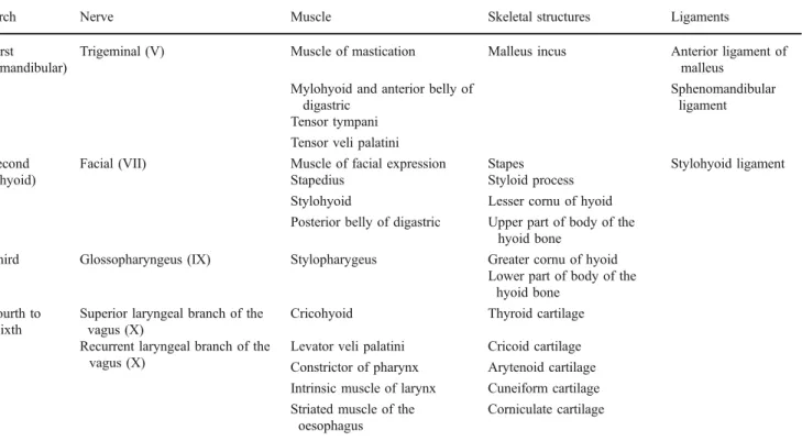
Table 1 Structures derived from branchial arch components
Arch Nerve Muscle Skeletal structures Ligaments First
(mandibular)
Trigeminal (V) Muscle of mastication Malleus incus Anterior ligament of malleus
Mylohyoid and anterior belly of digastric
Sphenomandibular ligament Tensor tympani
Tensor veli palatini Second
(hyoid)
Facial (VII) Muscle of facial expression Stapes Stylohyoid ligament Stapedius Styloid process
Stylohyoid Lesser cornu of hyoid Posterior belly of digastric Upper part of body of the
hyoid bone
Third Glossopharyngeus (IX) Stylopharygeus Greater cornu of hyoid Lower part of body of the
hyoid bone Fourth to
sixth
Superior laryngeal branch of the vagus (X)
Cricohyoid Thyroid cartilage Recurrent laryngeal branch of the
vagus (X)
Levator veli palatini Cricoid cartilage Constrictor of pharynx Arytenoid cartilage Intrinsic muscle of larynx Cuneiform cartilage Striated muscle of the
oesophagus
vascular axis and the facial nerve. The linguo-mandibulo-hyovertebral horseshoe-shaped sector comprises a mobile bony mandibular framework and a muscular suspension mechanism for the balance of the tongue and the laryngo-tracheal apparatus. The alveolodental sector comprises the teeth with their periodontium, and the relationship between the dental arches defines the occlusion, which is established at the time of the second dentition.
Classifications of otomandibular dysplasias
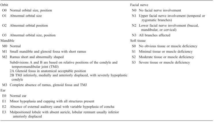
The wide spectrum of otomandibular dysplasias makes them difficult to classify, but these deformities can be broadly considered as involving skeletal, auricular and soft tissue. The OMENS classification [5] was developed as a comprehensive and stage-based approach, not only for the diagnosis but also for reconstruction of the skeletal and soft tissues (Table2).
Five distinct dysmorphic manifestations are described by this acronym: O, orbital asymmetry; M, mandibular hypoplasia; E, auricular deformity; N, nerve involvement and S, soft-tissue deficiency. Due to the many synonyms of each otomandibular dysplasia and associated injuries, Table 3 summarizes the main clinical and morphological abnormalities.
Imaging
The radiological evaluation at our institution included lateral and posteroanterior cephalometric radiographs, orthopantomogram (OPG) and a CT scan for all patients. CT scans were performed on an 8- or 16-multidetector CT scanner (LightSpeed, GE Medical Systems, Milwaukee, WI, USA). A craniocaudal acquisition covering the entire skull vault down to the inferior margin of the mandible was performed with a collimation of 3-mm slice thickness. To optimize spatial resolution and to obtain good-quality 3-D images, thin axial transverse images of 1.25-mm slice thickness were reconstructed for all patients. Both bone and soft-tissue algorithms were generated. Five-millimetre sections of brain algorithms were also reconstructed for the analysis of brain parenchyma for possible associated abnormalities.
Lateral and posteroanterior cephalometric radiographs, OPGs and CT images were analyzed by means of a consensus between two experienced radiologists.
Concerning the radiation dose delivered through each CT procedure, the as low as reasonably achievable (ALARA) principles were strictly applied as well as the guidelines from the Image Gently campaign [6–8]. A recent survey conducted at our institution [9] showed that CT dose index (CTDI) and dose-length product (DLP) values
Table 2 OMENS classification system
Orbit Facial nerve
O0 Normal orbital size, position N0 No facial nerve involvement
O1 Abnormal orbital size N1 Upper facial nerve involvement (temporal or zygomatic branches)
O2 Abnormal orbital position N2 Lower facial nerve involvement (buccal, mandibular, or cervical)
O3 Abnormal orbital size, position N3 All branches affected
Mandible Soft tissue
M0 Normal S0 No obvious tissue or muscle deficiency M1 Small mandible and glenoid fossa with short ramus S1 Minimal tissue or muscle deficiency M2 Ramus short and abnormally shaped S2 Moderate tissue or muscle deficiency
Subdivisions A and B are based on relative positions of the condyle and temporomandibular joint (TMJ)
S3 Severe tissue or muscle deficiency 2A Glenoid fossa in anatomical acceptable position
2B TMJ inferiorly, medially and anteriorly displaced, with severely hypoplastic condyle
M3 Complete absence of ramus, glenoid fossa and TMJ Ear
E0 Normal ear
E1 Minor hypoplasia and cupping with all structures present
E2 Absence of external auditory canal with variable hypoplasia of concha E3 Malpositioned lobule with absent auricle, lobular remnant usually inferior
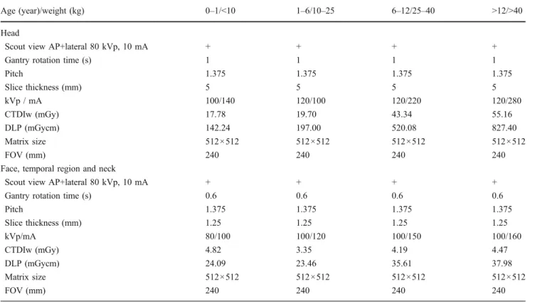
obtained for head CT in all ages were lower than data reported in neighbouring European countries, particularly Germany [10] and UK [11]. Our results were also compared with those of the 2007–2008 SFIPP/ISRN survey [12]. The 64-detector-row CT protocols currently in use at our institution are shown in Table4.
In order to lower the dose delivered by follow-up CT, follow-up studies were performed only when judged useful by the maxillofacial surgeon. In selected patients, the
maxillofacial surgeon used various orthodontic diagnoses and treatment planning software such as Quick Ceph 2000 (Quick Ceph Systems Inc., San Diego, CA, USA) to provide the cephalometric analysis.
MRI was performed on five patients using a 1.5-T MRI unit (Siemens Symphony, Siemens, Erlangen, Germany). Three-dimensional gradient-echo MPRAGE sagittal T1-weighted images were obtained with section thickness of 1.2 mm and a matrix of 256 × 224. Axial and
Table 3 Most common otomandibular anomalies with their synonyms and associated multisystem abnormalities
Name and synonyms
Mandible and mouth Ear external middle internal Facial nerve
Hemifacial microsomia
Mandibular hypoplasia Microtia, uni or bilateral Conductive hearing loss
Anomaly of the vestible, cochlea and semi-circular canals
VIIth nerve palsy
(HFM) Glenoid fossa hypoplasia Hypoplasia/Atresia of the external auditory meatus
Ossicular chain malformation
Absent internal auditory canal VIIth nerve canal abnormality Goldenhar
syndrome
Microstomia /Macrostomia Preauricular tags First branchial arch
syndrome
Cleft palate/lip Preauricular blind fistula Second branchial arch syndrome Bifid tongue Otomandibular dysostosis Malocclusion Oto-auriculovertebral (OAV) complex
Asymmetrical dental maturation
Mandibulofacial dysostosis
Mandibular hypoplasia (ramus and condyle, bilateral, symmetric)
Deformity or absence of the external auditory canal
Ossicular malformation
Deficient cochlea and vestibular apparatus (rare)
Abnormal course of the facial nerve canal (MFD) Obtuse angle of the mandible Skin tags Conductive hearing
loss Treacher-Collins
syndrome
Macrostomia Closed middle ear
cavity with osseous plate
Franceschetti-Zwahlen-Klein syndrome
Cleft lip (cleft palate)
Berry syndrome Malocclusion Branchio-oto-renal
syndrome
Possible association with hemifacial microsomia
Malformation of pinna Conductive sensorineural or mixed deafness
Internal auditory canal anomaly
(BOR) syndrome Prehelical pits Ossicle malformation Microcochlea Earpits-deafness syndrome Preauricular appendage Melnick-Fraser syndrome Preauricular sinuses Nager acro-facial dysostosis syn-drome
Rare variant of MFD with similar clinical features
Deformity or absence of the external auditory canal
Ossicular malformation
Deficient cochlea and vestibular apparatus (rare)
(AFD Nager) Skin tags Conductive hearing
loss Preaxial acrofacial
dysostosis
Closed middle ear cavity with osseous plate
Pierre Robin sequence
Hypoplasia of the mandible Low set ears (PRS) Obtuse mandibular angle
Pierre Robin syndrome Cleft palate Pierre Robin anomaly Pierre Robin complex
coronal T1-W images were then reconstructed. Axial and coronal T2-W fast spin-echo images with section thickness of 3 mm were also performed. High-resolution axial dual excitation true FISP (CISS) gradient-echo heavily T2-W images with a section thickness of 0.8 mm
were also obtained on the region of the inner and middle ear.
Due to the multiple associated abnormalities of the orbital and inner ear region, we think that MRI is indicated in all patients but could not be performed systematically. At
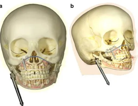
Fig. 1 a Line diagram shows osteotomy line of the ascending ramus of the mandible. b Movement of the screwdriver Table 4 64-detector CT acquisition protocols
Age (year)/weight (kg) 0–1/<10 1–6/10–25 6–12/25–40 >12/>40 Head
Scout view AP+lateral 80 kVp, 10 mA + + + +
Gantry rotation time (s) 1 1 1 1
Pitch 1.375 1.375 1.375 1.375 Slice thickness (mm) 5 5 5 5 kVp / mA 100/140 120/100 120/220 120/280 CTDIw (mGy) 17.78 19.70 43.34 55.16 DLP (mGycm) 142.24 197.00 520.08 827.40 Matrix size 512×512 512×512 512×512 512×512 FOV (mm) 240 240 240 240
Face, temporal region and neck
Scout view AP+lateral 80 kVp, 10 mA + + + + Gantry rotation time (s) 0.6 0.6 0.6 0.6
Pitch 1.375 1.375 1.375 1.375 Slice thickness (mm) 1.25 1.25 1.25 1.25 kVp/mA 80/100 100/120 100/150 100/160 CTDIw (mGy) 4.82 3.35 4.19 4.47 DLP (mGycm) 24.09 23.46 35.61 37.98 Matrix size 512×512 512×512 512×512 512×512 FOV (mm) 240 240 240 240
our institution, MRI and CT are performed under sedation in children younger than 6 years of age. In case of sedation failure, a second attempt was made under general anaes-thesia. Patients with severely narrowed airways, such as in Pierre Robin syndrome, were generally examined directly under general anaesthesia. Due to technical limitation MRI and CT could not be performed during the same anaesthesia in all patients.
An interactive combined review of CT data using axial images, maximum intensity projection (MIP) reconstruc-tions and 3-D volume-rendering technique (VRT) was applied to each examination using a commercially available workstation (Advantage Windows, GE Medical Systems). Fusion MRI–CT images could not be obtained but we used instead double-threshold shaded-surface display (SSD) images. Usually orthogonal axial, sagittal and coronal 2-D image reconstructions were performed in all patients. For
3-D SS3-D reconstructions, rotating and oblique views were also used to display mandible, external ear and external auditory canal abnormalities. The imaging features were compared to the surgical, anatomicopathological findings and postoperative follow-up imaging features.
Fig. 4 a Clinical photograph shows transcutaneous abutments of two temporal fixtures. b Ear epithesis retained by endosseous implants Fig. 3 Osteotomy of the right maxilla and application of the
distractor. a Intraoperative view of the maxillary distractor Fig. 2 a, b Schematic drawings
of the application of two dis-tractors on the maxilla and mandible in HFM show appli-cation of the maxillary and mandibular distractors after performing the Le Fort I omy and the horizontal osteot-omy of the mandibular ramus
Surgical techniques
Until the mid-1990s, surgical corrections of malformations were performed once skeletal growth was completed using corrective osteotomies and bone grafts. Miniaturization of osteodistraction devices allowed the application of orthopaedic principles of distraction described by Codivilla in 1905 and later by Ilizarov [13]. This principle is based on the fact that a bone can be lengthened after having performed an osteotomy if a force is regularly applied perpendicular to the osteotomy. Different types of distractors have been designed to achieve facial bone lengthening: they can be external, fixed to the bone by percutaneous pins, or internal, totally submerged beneath the skin or the oral mucosa, leaving access only to the activating rod of the device. The usual growth rate for the mandible is 1 mm per day and for the middle third of the face (maxilla, orbit etc.) not more than 0.3 mm per day.
The main advantage of distraction osteogenesis is that it allows early interceptive treatment of bone deformities. The other main advantage of distraction is that it also makes soft tissues grow around the distracted bone. Application of a distractor requires general anaesthesia and an outpatient or a short hospital stay procedure depending on the patient’s age, type of osteotomy (Fig.1) and parents’ understanding of the manipulation of the activating screwdriver. Correction of a micromandible causing respiratory distress to a newborn can be performed immediately after birth if it will prevent a tracheostomy. Early treatment of severe asymmetry is performed before a child begins school in order to lessen the psychological impact of the handicap.
Technically, a distraction osteogenesis needs a total corticotomy of the distracted bone after careful adaptation of the distractor through an intraoral approach for the mandible and the maxilla, trans-conjunctival and coronal approach for orbit and total middle third advancement. A
total mobilization of the distracted fragment is required before placing the device. Distraction in itself is started immediately on the first postoperative day and continued as long as needed to obtain a slight hypercorrection.
Treatment of different BAS, especially when associated with soft-tissue deficiencies, is one of the most difficult challenges for craniomaxillofacial surgeons. Different types of distraction osteogenesis have been advocated as effective techniques in the management of craniofacial deformities. The peculiarity of this technique is that the bone lengthen-ing achieved is accompanied by a simultaneous expansion of the surrounding soft-tissue envelope, which contributes to the stability of the reconstruction, therefore diminishing the risk of relapse. The simultaneous distraction of the maxilla and the mandible has already been described, using
Fig. 6 a Sixteen-year-old girl with left-side HFM. The lateral cephalometric radiograph shows asymmetrical mandibular angles (arrows). b The OPG shows hypoplasia of the left ascending ramus of the mandible and the coronoid process
Fig. 5 Clinical photograph shows left epithesis and BAHA retained on another implant
a Le Fort I osteotomy and an ascending ramus osteotomy [14]. However, one single distractor on the ascending ramus was used to distract the mandible and the maxilla using a maxillomandibular fixation. In order to reduce intermaxillary inconveniences for the patient (feeding problems and loss of weight, potential respiratory distress, etc.), a new technique of independent distraction of the maxilla and the mandible, each of them equipped by their own distractor, was described by our maxillofacial team in a recent publication (Figs.2and 3) [15].
A consolidation phase of 6–8 weeks is needed to allow the distracted callus to calcify and the new bone to remodel, after which the device is removed through the same incision as before. A reconstructive technique for hypoplastic mandible using a costal graft is also routinely used by several surgeons. The postoperative 3-D CT scan helps evaluate the gain of length of the ramus. Several months after surgery, the graft is sometimes seen osteointegrated to the native mandible. CT scans can help to identify contra-indications to the surgical procedure such as severe hypoplasia or the complete absence of the mandibular
ramus. CT is also mandatory in defining which type of surgical procedure should be used, for example, patients with a mild form of hemifacial microsomia need conven-tional maxillary and mandibular osteotomies whereas in patients with external ear aplasia, uni- or bilateral, the replacement of the ear can be achieved with an epithesis retained by endosseous implants (Fig. 4). These attach-ments (2 or 3) are inserted in the bone, untouched for a 2 month integration period and then connected by a gold or titanium bar allowing precise and atraumatic retention of the silicone prosthesis (Fig.4). The same procedure can be used in children affected by an ossicular chain malforma-tion in order to retain an auditory amplifier called a bone-anchored hearing aid (BAHA) (Fig. 5). It replaces the classic vibrator that hearing-impaired children wear with a band around their head.
In our study, CT was required for measuring the supramastoid bone thickness before ear epithesis proce-dures. As noted before in our study, CT was essential for studying the degree of middle ear anomaly and the status of the ossicles in order to plan surgery. Epithesis is less
Fig. 7 Eleven-year-old girl with right-side HFM. a Frontal view shows facial asymmetry and upward cant of the right labial commissure, with obliquity of occlusal plane. b OPG shows
the vertical mandibular asymmetry. c OPG shows initial position, before starting activation of the post-double distraction (mandibular and maxillary). d Post-double distraction (mandibular and maxillary). e At the end of distraction period there is correction of the occlusal plane
frequently used in case of outer ear aplasia: reconstructive surgery of the ear pinna using a Nagata technique has now become the gold standard for several surgeons.
Review of the syndromes
Hemifacial microsomia (Goldenhar syndrome, first bran-chial arch syndrome, second branbran-chial arch syndrome, otomandibular dysostosis, oto-auriculo-vertebral {OAV} Complex)
Hemifacial microsomia (HFM) manifests in a variable phenotype. Any structure derived from the first and second branchial arches may be involved [16]. Bilateral anomalies
are seen in up to 30% of patients. HFM is the second most common facial birth defect after cleft lip and palate [17], and may be linked with the VATER sequence. Boys are affected more frequently than girls (1.8:1). HFM is familial in 21% of patients and 45% of patients have affected relatives or siblings (10%). The mode of inheritance is thought to be autosomal- or X-linked-dominant in most cases. The multisystem abnormalities encountered in HFM are summarized in Table 3.
Teleradiography and pantomogram depict the size and shape of the face, orbit and mandible (Fig.6), and allow the anomaly to be graded according to the OMENS classifica-tion system (Table 2). These two techniques facilitate an accurate postoperative follow-up and monitoring of the bone growth under a mono- or double-distractor treatment (Fig. 7). CT with 3-D VRT images are useful in showing possible associated anomalies, for example in the cervical
Fig. 9 HFM. 3-D CT with bone surface-rendering
Fig. 8 Twenty-nine-year old man with HFM and Klippel-Feil syndrome in a 29-year-old man. a 3-D VRT images show bilateral assimilation between occipital condyles and the posterior arch of the atlas. b Thin-section coronal and sagittal CT reconstructions show only right-side assimilation
Fig. 10 Goldenhar syndrome in a 15-year-old girl. CT shows associated abnormality of lipoma of the corpus callosum
segment in the case of Klippel-Feil syndrome (Fig.8), and the 3-D CT with bone surface-rendering technique may serve to obtain a better appreciation of the global facial asymmetry (Fig.9). In children presenting with Goldenhar syndrome, the CT sagittal reconstruction technique helps to depict an associated lipoma of the corpus callosum (Fig.10). Patients with HFM present with a wide range of anomalies, but hearing loss is the most common associated functional deficit [18,19]. A temporal bone CT scan using thin slices allows for the assessment of the degree of stenosis and atresia of the external auditory canal (EAC), the status of the ossicles and other middle and inner ear
abnormalities such as hypoplasia or an abnormal course of the facial nerve (Figs. 11, 12 and 13). Although not favoured by maxillofacial surgeons yet, MRI offers a good illustration of any asymmetry or atrophy in the soft tissue and the masticator muscles, as well as a precise staging of the cochlear status using CISS sequences, and of the possible associated anomalies of the eye and mouth.
Mandibulofacial dysostosis (Treacher Collins, Franceschetti-Zwahlen-Klein syndrome, Berry-Treacher
Fig. 14 MFD, Treacher Collins syndrome. Lateral cephalometric radiograph shows hypoplasia of the malar bone, mandible and the mastoid. Note the metallic structures for the retention of the ear epithesis
Fig. 12 Middle ear abnormalities in a 16-year-old girl with right HFM. Axial CT shows dysplasia of right tympanic cavity with complete absence of right-side middle ear ossicles associated with hypoplasia of mastoid air cells
Fig. 13 Inner ear abnormalities. Right-side internal auditory canal hypoplasia in comparison with the normal left side in this patient with right HFM
Fig. 11 External ear abnormalities. Axial CT shows atresia of right EAC with absent right ear pinna
Collins syndrome, Franceschetti’s syndrome I, Thomson complex, Berry syndrome).
Mandibulofacial dysostosis (MFD) occurs in 1/50,000 live births and is an autosomal-dominant syndrome. About 60% of patients are new mutations. MFD is related to the TCS gene on chromosome 5q32-q33.1. The multiple
anomalies associated with MFD are summarized in Table3. The principal clinical manifestations of MFD are hypopla-sia of the malar bone and of the mandibular ramus [20] and condyle (Fig.14), with an associated antimongoloid slant of the palpebral fissures (Fig. 15). Differentiation from HFM may be difficult with overlapping features, but MFD mandibles are usually symmetrical and a greater frequency of lid colobomas and skin tags has been documented. Deformity or absence of the EAC and conductive hearing loss are frequent. A temporal bone CT scan using thin slices allows for the assessment of the degree of stenosis and atresia of the EAC, the status of the middle ear cavity, the absent or dysplastic and rudimentary ossicles or inner ear anomalies such as deficient cochlea and the abnormal course of the facial nerve canal.
Two-dimensional and 3-D CT reconstructions with VRT and bone- or skin-surface-rendering are helpful for more accurate staging and the 3-D planning of mandibular and external ear reconstructive surgery (Fig.16) [21].
Fig. 16 MFD. a 3-D CT with volume-rendering combining bone and soft-tissue windows. Left lateral view shows the malformation of the ascending ramus, absence of the temporal part of the zygomatic arch and absence of the EAC. b 3-D CT with SSD of the face using various soft-tissue settings offers a good depiction of the soft-tissue asymmetries and external ear lesions (small rudimentary ear pinna). Note also the absence of the EAC
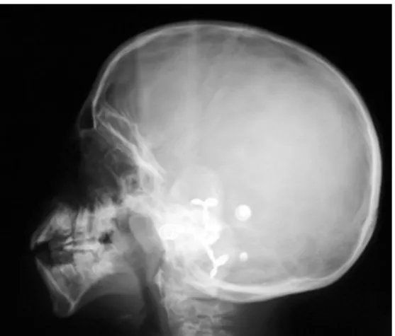
Fig. 17 Bilateral external ear aplasia in a patient with mandibulofacial dysostosis (Treacher Collins syndrome). Ear epithesis retained by endosseous implants. OPG shows transcutaneous abutments of two temporal fixtures
Fig. 15 Mandibulofacial dysostosis in a 6-year-old boy. OMENS stage: O3-M2B-E3-N0-S3 with bilateral hypoplasia of the mandibular ramus and condyle. a, b 3-D CT with surface-rendering shows
antimongoloid slant of the palpebral fissures. c Clinical photograph 1 year later, with BAHA and abutments for the retention of epithesis
Teleradiography and pantomogram facilitate an accu-rate postoperative follow-up and monitoring of bone growth under a mono- or double-distractor treatment (Fig.17).
Pierre Robin sequence (Pierre Robin syndrome, Robin anomaly, Pierre Robin complex)
Pierre Robin sequence (PRS) has no known genetic pattern. Girls are more affected than boys (F:M, 3:2). PRS occurs in about 1/8,500 live births. The main clinical features are micrognathia, glossoptosis and cleft palate. The anomalies associated with PRS are summa-rized in Table 3.
The radiological manifestations are: hypoplasia of the mandible, obtuse mandibular angle (Fig. 18) and cleft palate. Radiographs may show skeletal anomalies such as amelia, congenital amputations, syndactilies, clubfoot, congenital hip dislocation, rib and scapulae anomalies. Some features of the VATER complex may also be associated.
Branchio-oto-renal syndrome (ear pits-deafness syn-drome, BOR synsyn-drome, Melnick-Fraser syndrome)
Branchio-oto-renal (BOR) syndrome occurs in about 1/ 40,000 live births and represents 2% of all profoundly deaf children [22]. The syndrome is autosomal-dominant with variable expressivity and penetrance. Patients with BOR syndrome show multiple mutations in the EYA1 gene at 8q13. The anomalies associated with BOR are summarized in Table 3. BOR patients are characterized clinically by ear anomalies, preauricular pits, hearing loss and renal dysplasia. Temporal bone CT scan using thin slices and 2-D or 3-D reconstructions allows for the assessment of the external ear abnormalities, the status of the middle ear cavity, the absent or dysplastic and rudimentary ossicles or inner ear anomalies such as microcochlea [23, 24]. US and MRI may assess the associated renal anomalies.
Nager acrofacial dysostosis syndrome (AFD Nager, preaxial acrofacial dysostosis)
AFD Nager is a sporadic or familial rare variant of MFD. AFD Nager combines many features of MFD, with mandibular and malar hypoplasia, dysplastic ears, an antimongoloid slant of the palpebral fissures and deformi-ty or absence of the EAC and conductive hearing loss with limb abnormalities. The limb anomalies of AFD consist mostly of hypoplasia of the radial aspect of the hand, deformed forearm and limitation of the elbow extension. Some features of the VATER complex may also be associated. Radiographs may demonstrate the radial hypoplasia or aplasia and the hypoplasia of the thumb. The same imaging approach as used for patients with MFD seems adequate due to the clinical overlapping of the syndromes.
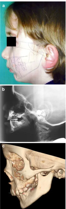
Fig. 18 Pierre Robin sequence in a 6-year-old girl. a Lateral picture with superimposed cephalometric analysis (Quick Ceph 2000). b Teleradiography shows hypoplasia of the mandible and obtuse mandibular angle. c 3-D CT with bone surface-rendering, lateral view shows retrognathism with mandibular hypoplasia. Note the global hypoplasia of the mandible without dysplasia
Conclusion
Complex first and second BASs are best understood using a multimodality imaging approach in order to increase diagnostic efficiency.
Extended knowledge of the embryology and anatomy of each branchial arch derivative is mandatory in establishing the diagnosis of facial and branchial arch syndromes. Pantomograms, cephalometric radiographs, 2-D and 3-D CT should be used together for morphological mapping prior to surgical treatment planning. For grading different BASs, axial CT is essential for providing the detailed analysis of inner, middle and external ear structures as well as the skull base anomalies. Three-dimensional CT becomes of prime importance for presurgical planning. Multimodality imaging is also essential for illustrating various associated brain and muscle anomalies and for the follow-up of postoperative patients, as well as facilitating a collaborative approach with maxillofacial surgeons.
Knowledge of current maxillofacial surgical instrumen-tation is mandatory in the follow-up imaging of reconstruc-tive surgery.
References
1. Moore K (1988) The developing human. Clinically oriented embryology, 4th edn. Saunders, Philadelphia
2. Castillo M, Mukherji SK (1995) Imaging of facial anomalies. Curr Probl Diagn Radiol 25:169–188
3. Castillo M (1994) Congenital abnormalities of the nose: CT and MR findings. AJR 162:1211–1217
4. Cobourne MT (2000) Construction for the modern head: current concepts in craniofacial development. J Orthod 27:307–314 5. Vento AR, LaBrie RA, Mulliken JB (1991) The O.M.E.N.S.
classification of hemifacial microsomia. Cleft Palate Craniofac J 28:68–76
6. Goske MJ, Applegate KE, Boylan J et al (2008) The ‘Image Gently’ campaign: increasing CT radiation dose awareness through a national education and awareness program. Pediatr Radiol 38:265–269
7. Goske MJ, Applegate KE, Boylan J et al (2008) The Image Gently Campaign: working together to change practice. AJR 190:273–274
8. The Alliance for Radiation Safety in Pediatric Imaging. www. Imagegently.org
9. Verdun FR, Gutierrez D, Vader JP et al (2008) CT radiation dose in children: a survey to establish age-based diagnostic reference levels in Switzerland. Eur Radiol 18:1980–1986
10. Galanski M, Nagel HD, Stamm G (2007) Results of a federation inquiry 2005/2006: pediatric CT X-ray practice in Germany. Rofo 179:1110–1111
11. Shrimpton PC, Hillier MC, Lewis MA et al (2006) National survey of doses from CT in the UK: 2003. Br J Radiol 79:968– 980
12. Brisse HJ, Aubert B (2009) CT exposure from pediatric MDCT: results from the 2007–2008 SFIPP/ISNR survey. J Radiol 90:207– 215
13. Ilizarov GA (1988) The principles of the Ilizarov method. Bull Hosp Jt Dis Orthop Inst 48:1–11
14. Ortiz Monasterio F, Molina F, Andrade L et al (1997) Simulta-neous mandibular and maxillary distraction in hemifacial micro-somia in adults: avoiding occlusal disasters. Plast Reconstr Surg 100:852–861
15. Scolozzi P, Herzog G, Jaques B (2006) Simultaneous maxillo-mandibular distraction osteogenesis in hemifacial microsomia: a new technique using two distractors. Plast Reconstr Surg 117:1530–1541
16. Charrier JB, Bennaceur S, Couly G (2001) Hemifacial micro-somia. Embryological and clinical approach. Ann Chir Plast Esthet 46:385–399
17. Tessier P (1976) Anatomical classification of facial, cranio-facial and latero-facial clefts. J Maxillofac Surg 4:69–92
18. Rahbar R, Robson CD, Mulliken JB et al (2001) Craniofacial, temporal bone, and audiologic abnormalities in the spectrum of hemifacial microsomia. Arch Otolaryngol Head Neck Surg 127:265–271
19. Carvalho GJ, Song CS, Vargervik K et al (1999) Auditory and facial nerve dysfunction in patients with hemifacial microsomia. Arch Otolaryngol Head Neck Surg 125:209–212
20. Pruzansky S (1969) Not all dwarfed mandibles are alike. Birth Defects 1:120–129
21. Papadopoulos MA, Christou PK, Christou PK et al (2002) Three-dimensional craniofacial reconstruction imaging. Oral Surg Oral Med Oral Pathol Oral Radiol Endod 93:382–393
22. Robson CD (2006) Congenital hearing impairment. Pediatr Radiol 36:309–324
23. Binaghi S, Gudinchet F, Rilliet B (2000) Three-dimensional spiral CT of craniofacial malformations in children. Pediatr Radiol 30:856–860
24. Gonzalez GE, Caruso PA, Small JE et al (2008) Craniofacial and temporal bone CT findings in cleidocranial dysplasia. Pediatr Radiol 38:892–897