The Communication Links in ProCell
-
Intel386EX Peripheral Device Interfaces
by
Ning Ye
Submitted to the Department of Electrical Engineering and Computer Science
in Partial Fulfillment of the Requirements for the Degrees of
Bachelor of Science in Electrical Engineering
and Master of Engineering in Electrical Engineering
at the Massachusetts Institute of Technology
ENO
MASSACHUSETTS INSTITUTE
January
10, 2000
OF TECHNOLOGYCopyright 2000 Ning Ye. All rights reserved.
JUL 2 7 2000
LIBRARIES
The author hereby grants to M.I.T. permission to reproduce and
distribute publicly paper and electronic copies of this thesis
and to grant others the right to do so.
Author
Department of Electiical ngineering and Computer Science Certified by
Accepted by
Kamal Youcef-Toumi
TJysis Suervisor
Arth r C.
ith
Chairman, Department Committee on Graduate Theses
7-The Communication Links in ProCell
-
Intel386EX Peripheral Device Interfaces
by
Ning Ye
Submitted to the
Department of Electrical Engineering and Computer Science
January 10, 2000
In Partial Fulfillment of the Requirements for the Degrees of
Bachelor of Science in Electrical Engineering
and Master of Engineering in Electrical Engineering
ABSTRACT
The communication links in a photoresist processing system are crucial issues of the
automation in semiconductor production facilities.
On the module control level in
ProCell, the Intel386EX microprocessor interfaces with the peripheral devices via three
different data transfer protocols. Both the hardware and the software for these three
protocols are discussed in detail. The device drivers for two of the protocols, RS-232
serial communication and Controller Area Network are written in C in a VxWorks,
real-time operating system. A set of diagnostic procedures called echo is developed to test the
driver for a serial device SC26C92 in RS-232 serial communication. Overall testing was
done in both hardware and software.
Thesis Supervisor: Kamal Youcef-Toumi
Acknowledgements
The author wishes to acknowledge some of the people who contributed to the
completion of this thesis. The Track Division of Silicon Valley Group, Inc. in San Jose,
California provided a wonderful opportunity for me to carry out the work for this thesis.
I must thank the person who helped me the most, Charles Lee, my supervisor at SVG
who was instrumental in helping me define the research topic and providing a stimulating
research environment. Many engineers at SVG who worked on the ProCell system
contributed to the thesis work both directly and indirectly.
I would like to thank Professor Kamal Youcef-Toumi for traveling all the way to
San Jose to help me with writing of this thesis and directing the course of the thesis work.
His time and patience is greatly appreciated.
Additionally, I would like to thank my parents for their unending encouragement
and support. Without them I surely would never have reached this point.
Ning Ye
Massachusetts Institute of Technology
January, 2000
Table of Contents
ABSTRACT ...
11
Acknow ledgements ...
iii
Table of Contents ...
iv
List of Figures ...
vi
Chapter 1: Introduction...1
Chapter 2: Photoresist Process...
3
2.1 Introduction...3
2.2
Photoresist Process ...
3
2.3 SVG's ProCell System ...
4
2.4 ProCell's Control System Architecture ...
5
2.5 Summ ary...7
Chapter 3: M odule Controller System ...
8
3.1 Overview ...
8
3.2 M odule Controller Board...
9
3.2 Com munication Protocols...
10
3.2 Summ ary...11
Chapter 4: Device and Driver for RS-232 Serial Communication...
12
4.1 Introduction...12
4.2 Advantages of Serial Data Transmission in ProCell...
12
4.3 Philips SC26C92 DUART ...
13
4.4 Device Driver for Philips SC26C92 DUART...
14
4.5 Introduction to Devices and Drivers in VxW orks...
16
4.5.1 I/O system in VxW orks...
16
4.5.2 Devices and Drivers ...
18
4.5.3 Opening a File/Device ...
19
4.5.4 Reading Data from the File/Device...21
4.5.5 Closing a File ...
25
4.6 Test for SC26C92 Driver...
25
4.6.1 Test Set-up ...
25
4.6.2 "Echo" ...
26
4.6.3 SCC Test...
28
4.7 Sum mary...30
Chapter 5: Controller Area Network (CAN) ...
31
5.2.1 Principles of Data Exchange ...
31
5.2.2 CAN Protocol...32
5.2.3 Error Detection...
34
5.3 CAN Controller 82527 ...
35
5.4 Driver for CAN Controller 82527...36
5.5 Sum m ary...38
Chapter 6: Parallel Com m unication ...
40
6.1 Introduction...40
6.2 Interface between 386 and Coater's Arms...
40
6.3 Advanced Multi-Axis Motion Control Chipset, MC1401A by PMD...41
6.4 Data Transfer Protocol...
42
6.5 Sum m ary...44
Chapter 7: Conclusions...
45
Appendices...47
Appendix A : Source Code for
SCC
Driver (scc.c) ...
47
Appendix B : Source Code for echo (sectest.ccp) ...
61
Appendix C: Source Code for PMD Chipset's Interface (pmdio.c) ...
67
Appendix D : Source Code for M otion Control (m otion.o)...118
List of Figures
Figure 1: Silicon Valley Group's ProCell system...
4
Figure 2: View of ProCell from top down...5
Figure 3: ProCell Systems Architecture / Communication Diagram...6
Figure 4: Block diagram of ProCell's control system...8
Figure 5: The Module Controller Board in ProCell and the Interfaces...10
Figure 6: Interfacing RS-232 ports to devices. ...
14
Figure 7: Call to I/O Routine Openo. [part 1]...22
Figure 8: Call to I/O Routine Openo. [part 2]...
23
Figure 9: Call to I/O read Routine...24
Figure 10: Set-up for "Echo" Test...
26
Figure 11: Wiring diagram between communication channel 1 &2 (Null Modem Wiring).
...
2 6
Figure 12: Block Diagram of Echo between Comi and Com2. ...
27
Figure 13: Message frame for standard format (CAN specification 2.OA). ...
33
Figure 14: Physical CAN connection. ...
36
Chapter 1: Introduction
Semiconductor manufacturing has been such a rapidly growing industry that it has
enormous impacts on even the most mundane tasks in our daily life.
Semiconductor
industry's products nowadays are found not only in the high tech electronic goods which
semiconductors have been traditionally associated with, but in toys and household
appliances as well. The semiconductor equipment industry produces the process tools
that are used in the complex manufacturing of semiconductors. With the continued
expansion of Internet-related technologies and increasing demand for semiconductors in
new electronics, semiconductor equipment industry has been growing tremendously in
the last decade as a result of chip manufacturer's increasing production.
This thesis addresses the photoresist processing tools in the semiconductor
equipment industry. A photoresist processing system is usually composed of several
process modules, i.e. coaters, developers, etc. The communications among the individual
modules, as well as the communications between modules and the module controllers,
have always been crucial issues of the automation in semiconductor production facilities,
and must be done in a timely and precise way. Failure in communications in the control
system can lead to severe consequences to possibly cause paralysis of the entire machine.
This thesis presents the architecture of the software control system in an
automated photoresist processing machine.
It focuses on the communications and
interfaces between the host microprocessors and the modules. Thesis work includes
ensure the proper functioning of the driver, and parallel communication between the
microprocessor and a motion control chipset.
Chapter 2 gives a rudimentary introduction on photoresist process and Silicon
Valley Group's ProCell, a photoresist processing system. Chapter 3 focuses on the
module controller board in ProCell. It illustrates how the microprocessor used in module
control interfaces with the modules. Three communication protocols are introduced at
the end of Chapter 3. Chapter 4, Chapter
5
and Chapter 6 address these three types of
communication protocols, RS-232 serial communication, Controller Area Network
Chapter 2: Photoresist Process
2.1 Introduction
This chapter provides a basic introduction to the integrated circuit (IC) fabrication
and Silicon Valley Group (SVG)'s ProCell system. SVG's Track Systems Division' is a
world's leading manufacturer of the complete family of photoresist processing products.
A brief description of the essential process in IC fabrication will help understanding
SVG's ProCell system, the latest photoresist processing system, designed and
manufactured by SVG's Track Systems Division.
2.2 Photoresist Process
The fundamental unit of IC manufacturing is a silicon wafer.
The essential
process in IC fabrication is the imaging, alignment, and transfer of complex patterns onto
the silicon wafer. A photolithography machine called stepper is used to transfer patterns
from an optical plate called a mask, to photoresist on the wafer. Photoresist is a
photosensitive material that coats the top surface of the wafer [Howe '97]. It dissolves in
developer if it has been exposed to light. Patterns are transferred to a wafer by covering
the wafer with photoresist, exposing a pattern in the photoresist and then using the
patterned photoresist as a mask through which to implant dopants or etch the material.
Photoresist processing is a pivotal function, which includes numerous steps performed
repeatedly, such as coating, developing and baking of silicon wafers.
2.3 SVG's ProCell System
ProCell
from
SVG's
Tracks
Systems
Division
is
an
evolutionary
photolithography processing system that provides a complete line of photoresist
processes, including vapor prime, vacuum-dehydration bake, photoresist coat, hot plate
bake, and wafer temperature control using chill plates. Designed around the principle of
symmetry, ProCell's cluster configuration jump-starts productivity by departing from the
previous linear track models.
This design eliminates the bottlenecks that plague
conventional track systems. Wafers flow smoothly through ProCell with the minimum
number of moves.
In fact, this is currently the only platform that can complete the
lithography process in just 12 perfectly balanced moves [Silicon '99].
Figure 1 is a
picture of SVG's ProCell.
Figure 2 shows the top view of ProCell's machine
configuration.
Figure 2: View of ProCell from top down.
32.4 ProCell's Control System Architecture
This section gives a brief description of SVG's ProCell's architecture of its
control system.
This description gives a background of the thesis work, and shows
where the work done in this thesis fits in the big picture of ProCell's overall control
system.
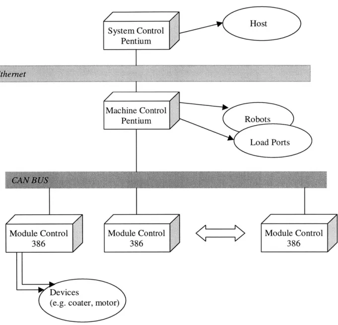
Figure 3 illustrates ProCell's software control system. At the top layer, System
Controller Board is a Pentium based single board computer running Windows NT 4.0.
This is used to host the system control software, where the user displays and operator
controls as well as factory interfaces are provided.
The mid-layer is the Machine
Controller Board, which is also the same basic Pentium based SBC board, hosting the
machine control software. It provides high-level module controls, load ports and robot
controls. A Module Controller Board is based on an Intel386EX microprocessor with 1/0
and motion controllers to control each process module. The Module Controller Boards
share the same VxWorks real time operating system environment as the Machine
Controller Board.
z _-
Host
System Control N
Pentium
Machine Control
Pentium
Robots
Load Ports
Module Control
Module Control
Module Control
386
386
386
Devices
(e.g. coater, motor)
There are 7 main communication links in ProCell Control Systems.
1) Pentium Window NT to Pentium VxWorks communication links over Ethernet.
2) Pentium Window NT to Pentium peripherals and VxWorks communication links via
VME BUS.
3) Pentium VxWorks to 386 VxWorks communication links via CAN-BUS and
VME-BUS.
4) Pentium VxWorks to OEM (Original Equipment Manufacturer) communication links
via serial or parallel signals.
5)
386 VxWorks to 386 VxWorks peer to peer communication links via CAN-BUS.
6) 386 to 1I/
control chips and OEM communication links via serial, parallel, or
electrical signals.
7) Pentium Windows NT to GEM/SECS (General Equipment Manufacturer /
Semi-conductor Equipment Communication Set) hose via HSMS protocol over Ethernet.
2.5
Summary
This chapter gave a brief introduction to semiconductor industry's photoresist
process and described ProCell, SVG Track Systems Division's new photoresist
processing system on the whole, as well as its overall control system architecture. The
following chapters will go on to discuss the module controller system in ProCell, with a
Chapter 3: Module Controller System
3.1 Overview
The Module Controller Boards in ProCell system are based on an Intel386EX
microprocessor with I/O and motion controllers to control each process module in
ProCell (link 6). Refer to Figure 4 for the block diagram of ProCell's overall control
system to see where the Module Controller Boards are located at in the overall control
system.
System Control
Pentium
Machine Control
Pentium
Module Control
Module Control
Module Control
386
386
386
Figure 4: Block diagram of ProCell's control system.
Controls of modules at module level reduce the operation delays by the controller
system, which used to be a key reliability/process concern in the past, because the delays
have been seen to arise from the fact that all controls were at high level in the previous
systems. Distributed module control provides stand-alone module tests. Decisions are
made at module level so that there is less communication to system control level.
3.2 Module Controller Board
Link 6, which is the interface between the Intel386EX-based Module Controller
Board and the modules, together with link 5's CAN-BUS are where the work of this
thesis has been focused on at SVG's Track Division. The emphasis of the thesis will be
placed on 386 peripheral device interfaces, mostly on the device drivers' side. The
Intel386EX-based Module Controller Boards share the same standard VxWorks real time
operating system.
Figure
5
shows the block diagram for typical interfaces between Intel386EX
microprocessor and the peripheral devices, and communication between two
microprocessors.
The heart of the Module Controller Board is an Intel386EX microprocessor. In
addition to memory and A/D converters, the microprocessor is directly interfaced with a
Universal Asynchronous Receiver/Transmitter (UART), an 82527 serial communication
controller which is a device that performs serial communication according to CAN
protocol, and an advanced multi-axis motion control chipset. They will be discussed in
Intel386Ex-based Module Controller
Motion Controller
Motor in a module
Motion
Controller
Intel
386EX
{RS-232
serial
UART
M
communication ports }
P
CAN Devices
CAN BUS
FLASH
A/D
Another
(Memory)
Converter
Intel 386EX
---Figure 5: The Module Controller Board in ProCell and the Interfaces.
3.2 Communication Protocols
RS-232 Serial Communication
Most of the modules communicate with the Module Controller Boards via RS-232
serial ports. In order for the RS-232 serial ports to be connected to the microprocessor,
serial transmission needs to be converted to parallel transmission via UART. A Dual
UART device SC26C92 is used here. Chapter 4 will discuss the serial device driver in
Controller Area Network (CAN)
In ProCell, peer module controllers are connected via a serial bus using Controller
Area Network (CAN) protocol. On the Module Controller Board, the microprocessor is
connected with a CAN controller 82527 which, in turn, connects to a CAN Transceiver to
perform the serial communication. The protocol for CAN, the driver for CAN devices in
VxWorks, as well as the physical CAN connection are described in Chapter 5.
Parallel Communication
The MC1401A used here is a 2-IC general-purpose motion control chipset that
provides closed-loop digital servo control for motors.
The chipset is controlled by the
host microprocessor that interfaces with the chipset via an 8-bit, bi-directional port. All
communications to/from the chipset consist of packet-oriented messages. A packet is a
sequence of transfers to/from the microprocessor resulting in a chipset action or data
transfer. Chapter 6 will address the protocol and the hardware interface for the parallel
communication.
3.2 Summary
This Chapter gave an overall illustration of the Intel386EX-based Module
Controller Board, as well as the major components on the board. Three communication
protocols were introduced in this Chapter, RS-232 serial communication, Controller Area
Network (CAN) and parallel communication. The next three chapters will be discussing
Chapter 4: Device and Driver for RS-232 Serial Communication
4.1 Introduction
This Chapter presents the thesis work done on the RS-232 serial communication
device driver in VxWorks on the module control level in ProCell. It begins by discussing
the advantages of serial over parallel data transmission in the ProCell. Then it moves on
to describe a DUART Philips SC26C92 and its device driver in VxWorks, a real-time
operating system run on ProCell. An introduction on I/O system and device driver in
VxWorks in general is given in section 4.4 for a better understanding of
SCC
driver.
Section
4.5
focuses on the
SCC
test, a diagnostic procedure written for testing of SCC
driver and the serial communication between two RS-232 ports.
4.2 Advantages of Serial Data Transmission in ProCell
Serial communication is vastly used in ProCell, between the module controllers
and the modules. Using serial data transfer rather than parallel transfer in ProCell has its
advantages.
Serial cable can be much longer than parallel cables. The serial port
transmits a '1' as -3 to
-25
volts and a '0' as +3 to
+25
volts whereas a parallel port
transmits a '0' as Ov and a 'I' as 5v. Therefore the serial port can have a maximum swing
of 50V compared to the parallel port which has a maximum swing of 5
Volts. Thus cable
loss is not going to be as much of a problem for serial cables than they are for parallel
ones. This is especially desirable in large wafer processing machines like ProCell, where
the host computers could be placed far away from the process modules in the system.
cable (Null Modem Configuration) is a lot cheaper that running 19-core or 25-core cable.
The above two features are both desirable in setting up test environment during the
engineering process as well.
4.3 Philips SC26C92 DUART
The
Philips
Semiconductors
SC26C92
Dual
Universal
Asynchronous
Receiver/Transmitter (DUART) is a single-chip serial communications device that
provides two full-duplex asynchronous receiver/transmitter channels in a single package.
It interfaces directly with the Intel386EX microprocessor.
When the SC26C92 is
conditioned to transmit data, the transmitter converts the parallel data from the
microprocessor to a serial bit stream on the TxD output pin. It automatically sends a start
bit followed by the programmed number of data bits, an optional parity bit, and the
programmed number of stop bits. The least significant bit is sent first.
When the
SC26C92 is conditioned to receive data, the receiver looks for a mark-to-space transition
of the start bit on the RxD input pin. If a transition is detected, the state of the RxD pin
starts getting sampled every certain time interval depending on the clock until the proper
number of data bits and parity bit (if any) have been assembled, and one stop bit has been
detected. The least significant bit is received first. The data is then transferred to the
DURT
8-i
palel data
DO-D8
Tx/Rxl
RS-232
Level
(
RS-232
Converter
Port 1
Tx/Rx2MAX232
RS-232
Port 2
SC26C92
Figure 6: Interfacing RS-232 ports to devices.
Figure 6 shows how to interface RS-232 ports to devices. Note that almost all
digital devices require either TTL or CMOS logic levels. Therefore, the first step to
connecting a device to the RS-232 port is usually transforming the RS-232 levels back
into 0 and
5
Volts. This is done by an RS-232 Level Converter, MAX232 here.
4.4 Device Driver for Philips SC26C92 DUART
Device drivers are program routines that let peripheral devices communicate with
operating systems. The driver for the Philips SC26C92 is implemented as a standard
VxWorks terminal driver making use of the tyLib () system library. How VxWorks
provides terminal devices and device drivers and VxWorks' I/O system will be described
in further detail in the next section.
Refer to
Scc.c
in Appendices for the tty
driver for the Philips SC26C92
tySCCDrv
Before a diver is used to drive a device, it must be initialized by calling the
program routine: tySCCDrV( ). The initialization routine installs the driver in the I/O
system, connects to any interrupts used by the devices serviced by the driver, and
performs any necessary hardware initialization.
A single driver for a serial
communications device can often handle many separate channels. This routine should be
called exactly once before any read's, write's, or tySCCDevCreate's.
tySCCDevCreate
This routine adds terminal devices that are to be serviced by the driver (initialized
by routine tySCCDrv) to the 1/0 system. Before a terminal device can be used, it has to
be created first. This is done through calling the routine tySCCDrvCreate. Each
serial communication port to be used will have exactly one terminal device associated
with it after this routine has been called.
TySCCDrvCreate takes five arguments, and returns OK (1)
if a terminal
device has been successfully created, or Error (0) otherwise.
STATUS tySCCDevCreate (name,
channel,
rdBufSize,
wBufSize, baudRate)
Name
name to use for this terminal device, i.e. "/tySCC/O"
Channel
physical channel for this device
RdBufSize
read buffer (input buffer) size, in bytes
WbufSize
write buffer (output buffer) size, in bytes
Baudrate
baud rate to create the terminal device with, i.e. 9600
For instance, to create a terminal device "/tySCC/0", with input and output
buffers of size 512 bytes, at 9600 baud rate, the proper call is:
TySCCDevCreate ("/tySCC/0", 0,
512,
512, 9600);
4.5 Introduction to Devices and Drivers in VxWorks
4.5.1 1/0 system in VxWorks
VxWorks is a high-performance networked real-time operating system. It runs on
a variety of hardware, including the Intel 386 based system.
This section gives a
background on VxWorks I/O system, with an emphasis on devices and drivers in
VxWorks.
In VxWorks, applications access I/O devices by opening named files. A file can
refer to one of the two things:
A "raw" device such as a serial communication channel.
A logicalfile on a random-access device containing a file system.
Consider the following named files:
/usr/filel
/pipe/mypipe/
/tyCo/0
The first one refers to a file called filel
on a disk device called /usr. The
second one is a pipe named mypipe. The third one refers to a physical serial channel.
However, I/O can be done to or from any of these in the same way. Within VxWorks,
they are all called files, even though they refer to very different physical objects [Wind
'97].
Basic 1/0 is the lowest level of I/O in Vxworks. The following are a few basic
open ():
Open a file/device.
close ():
Close a file/device.
read 0:
Read a previously created or opened file.
write
() :
Write a previously created or opened file.
At the basic I/O level, files are referred to by a file descriptor, or fd. An fd is a
small integer returned by a call to open(). The other basic 1/0 calls take an fd as a
parameter to specify the intended file. Before 1/0 can be performed to a device, an fd
must be opened to that device by invoking the open () routine.
After an fd is obtained by invoking open(),
tasks can read bytes from a file
with read () and write bytes to a file with write
().
The arguments to read () are
the fd, the address of the buffer to receive input, and the maximum number of bytes to
read:
int
nBytes
=
read
(fd, &buffer,
maxBytes);
The read
()
routine waits for input to be available from the specified file/device,
and returns the number of bytes actually read.
The arguments to write () are the fd, the address of the buffer that contains the
data to be output, and the number of bytes to be written:
int
actualBytes
=
write
(fd, &buffer, nBytes);
The write () routine ensures that all specified data is at least queued for output
before returning to the caller, though the data may not yet have been written to the device
(that is driver dependent).
Another very important basic I/O routine is 1/0 control: iocti
() routine. It is
an open-ended mechanism for performing any I/O functions that do not fit the other basic
I/O calls.
Examples include determining how many bytes are currently available for
output and setting device-specific options. The arguments to the iocti () routine are
the fd, a code that identifies the control function requested, and an optional
function-dependent argument.
Result
=
ioctl (fd, function, arg);
For example, the following call uses the FIOFLUSH function to discard all the
bytes in the input or output buffer:
Status
=
ioctl (fd, FIOFLUSH, 0);
See scctest cpp in the Appendices for how all the basic functions mentioned
above are used.
4.5.2 Devices and Drivers
Devices are handled by program modules called drivers. The VxWorks 1/0
system is flexible, allowing specific device drivers to handle the basic 1/0 functions
mentioned in the last section.
For serial 1/0 devices, VxWorks provides terminal device drivers (tty drivers).
VxWorks serial I/O devices are buffered serial byte streams. Each device has a ring
buffer (circular buffer) for both input and output. Reading from a tty device extracts
bytes from the input ring. Writing to a tty device adds bytes to the output ring. The
size of each ring buffer is specified when the device is created during system
initialization. The tty devices respond to the ioctl () functions mentioned in the
previous text.
A device driver implements the basic I/O functions for a particular kind of a
as read (), write (), etc. although some of the routines can be omitted if the functions
are not operative with that device.
In VxWorks, some drivers are capable of servicing many instances of a particular
kind of device. For example, a single driver for a serial communications device can
handle many separate channels that differ only in a few parameters, such as device
address.
Devices are added to the 1/0 system dynamically by calling the internal I/O
routine isoDevAdd 0. The arguments to iosDevAdd () are the address of the device
descriptor for the new device, the device's name, and the driver number of the driver that
services the device.
Refer to file
scc
. c in the Appendices for the use of
iosDevAdd).
4.5.3 Opening a File/Device
Files/devices are opened with open(). The I/O system searches the device list
for a device name that matches the file name (or an initial sub-string) specified by the
caller. If a match is found, the I/O system uses the driver number contained in the
corresponding device header and call the driver's open routine in the driver table.
The 1/0 system must establish an association between the file descriptor used by
the caller in subsequent 1/0 calls, and the driver that services it.
The I/O system
maintains these associations in a table called fd table. This table contains the driver
number and an additional driver-determined 4-byte value. The driver value is the internal
descriptor returned by the driver's open routine, and can be any nonnegative value the
such as read (), write (),
iocti () and close (),
this value is supplied to the
driver in place of the fd in the application-level I/O calls.
drvnum value
0
1
2
3
4
fd Table
Example of Opening a Device
In Figure7 and Figure 8 [Wind '97], a user calls openo to open the device /xxO.
The following series of actions take place in the I/O system:
1) It searches for the device list for a device name that matches the specified device
name: /xxO.
2) It reserves a slot in the fd table, which is used if the open is successful.
3) It then looks up the address of the driver's open routine, xxOpen (),
and calls that
routine. Note that the arguments to xxopen() are transformed by the I/O system
from the user's original arguments to open
().
The first argument to xxOpen () is
a pointer to the device descriptor the 1/0 system located in the full file name search.
The next parameter is the remainder of the file name specified by the user, after
string. The last parameter is the file access flag, in the case ORDONLY; this is, the
file is opened for reading only.
4) It executes xxopen () , which returns a value that subsequently identifies the newly
opened file. In the case, the value is the pointer to the device descriptor. This value
is supplied to the driver in subsequent 1/0 calls that refer to the driver being opened.
5) The 1/0 system then enters the driver number and the value returned by xxopen ()
in the reserved slot in the fd table. Again, the value entered in the fd table has
meaning only for the driver, and is arbitrary as far as the 1/0 system is concerned.
4.5.4 Reading Data from the File/Device
The routine read () is used to obtain input data from the device. The specified fd
is the index to the fd table for this device.
The 1/0 system uses the driver number
contained in the table to locate the driver's read routine,
xxRead ().
The I/O system
calls xxRead (), passing it the identifying value in the fd table that was returned by the
driver's open routine,
xxOpen ().
Again, in this case the value is the pointer to the
device descriptor. The driver's read routine then does whatever is necessary to read data
from the device. The process for user calls to write () and iocti
() follow the same
User Call:
Driver Call:
fd
=
open ("/xxO", ORDONLY)
xxdev
=
xxOpen (dev-pointer, " ",
ORDONLY);
[1] 1/0 system finds
name in device list.
[2] 1/0 system reserves
a slot in the fd table.
[3]
1/0 system calls driver's
open routine with pointer to
device descriptorFD TABLE:
drvnum
value
0
1
2
3
4
DEVICE LIST:
'
DRIVER TABLE
create
Remove
o n
close
Read
write
ioctl
0
1
2 xxOpen
3
4
Figure 7: Call to I/O Routine open
().
[part 1]
"/xx1"
2
"/dkO/" ",/x0"1
2
Device-Dependen
tdataUser Call:
fd
=
open ("/xxO", ORDONLY)
[6] I/O system returns
index in fd table of new
open file (fd
=
3).
FD TABLE
DEVICE LIST
DRIVER TABLE
Driver Cal
xxdev = xxOpen[5] 1/0 system enters driver number
and identifying value in reserved fd
table slot.
mum
value
3
2
xxdev
4
\
1
1
1:
(dev-pointer, " ",ORDONLY);
[4] Driver returns any
identifying value, in the case
the pointer to the device
descriptor.
0
1
2
"/dkO/"
"/xxO"
"/xx1"_1
2
2
evice-ependen
t atacreate
Remove
open
close
read
write
ioctl
0
1
2
xxopen
3
4
Figure 8: Call to I/O Routine open ().
[part 2]
I
User Call:
Driver Call:
n
=read(fd, buf, len);
FD TABLE
DEVICE LIST
DRIVER TABLE
1/0 system transforms the user
routine calls into driver routine
replacing the fd with the value
by the driver's open routine, xx
drvnum value
0
1
2
3
2
xxdev
4\z
_
n
=
xxRead (dev-pointer, buf, len);
A
s I/O
calls
returned
Openo.
"/dko/'
"/xxO"
"/xx
1"
1-
2
2
evice-ependen
t atacreate
Remove open close read write ioctl0
1
2 xxReadO)
3
4
4.5.5 Closing a File
The user terminates the use of a file by calling close ().
As in the case of
read ), the 1/0 system uses the driver number contained in the fd table to locate the
driver's close routine. In the example driver, no close routine is specified; thus no driver
routines are called. Instead, the I/O system marks the slot in the fd table as being
available. Any subsequent references to that fd cause an error. However, subsequent
calls to open () can reuse that slot.
4.6 Test for SC26C92 Driver
Most of the modules on Procell communicate with the Intel386EX-based Module
Controller Board via serial communication.
Therefore, it is pivotal to ensure the
reliability of the serial device driver.
54.6.1 Test Set-up
One way to test the SCC driver is the echo method. This test method involves a
very simple set-up: one Module Controller Board, an extension I/O board, and a cable
connecting the two communication devices/channels to be tested. See Figure 10 for the
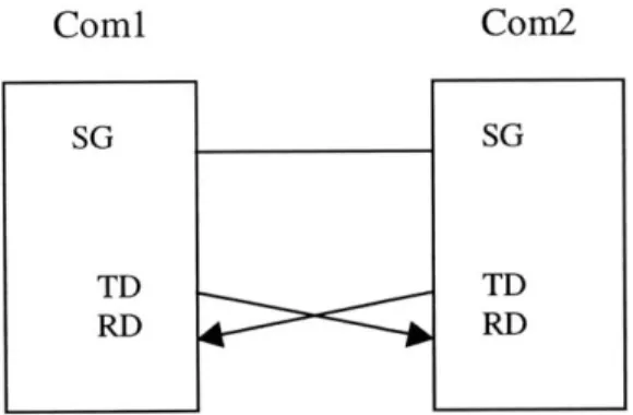
illustration of the set-up. These two communication devices/channels are wired up with
the method of Null Modem (Figure 11). The aim is to make the computer think it is
talking to a modem rather than another computer. Any data transmitted from the first
communication device/channel must be received by the second thus TD is connected to
Signal Ground (SG) must also be connected so both grounds are common to each
device/channel.
Module Controller Board
Extension I/O Board
Corn
Com2
"ECHO"
Figure 10: Set-up for "Echo" Test.
Comi
SG
TD
RD
Com2
SG
TD
RD
Figure 11: Wiring diagran between communication channel 1 &2 (Null Modem Wiring).
4.6.2 "Echo"
The following text describes echo in five steps, which are also illustrated in a
block diagram in Figure 12.
I.
Write a message in the output buffer of communication channel 1 using the
II.
Since channel l's TD line is wired together with channel 2's RD line, reading
from channel 2 via a read () routine gets the message sent from channel 1 and
puts it in channel 2's input buffer.
III.
Then use the write () routine to place that message read from channel 2 into
channel 2's output buffer.
IV.
Likewise, since channel 2's TD line is wired together with channel I's RD line,
reading from channel 1 now will get that message.
V.
Compare this received message with the originally sent message at the beginning
of the process to see if they have the same content. If they do, the echo test
returns a positive result.
message
"!@#$%AI. write( ... )1.ra (.
V.
Output Buffer
Input Buffer
compare
the III. write(.)
messages
Input
Buffer <Output
Buffer
7 IV. read(...)
"!1@#$%^
COM
COM
"echoed" message
4.6.3 SCC Test
This section describes in detail, in terms of VxWorks, how to implement the idea
of echo method in doing the SCC test.
* Initialize the SCC driver via a call to a tySCCDrv () routine. As mentioned in an
earlier section, tySCCDrv () has to be called exactly once before any terminal
devices can be created.
" Create two terminal devices: channel 1 and channel 2. Specify the input/output buffer
size for each terminal, i.e. 1024 bytes for buffer size. Specify the baud rate, i.e.
19200bps.
The devices have to be successfully created in order for any data
transmission to happen. Every device has a unique name. No multiple devices can
share the same device name. If a device with a specified name has already been
created, an error message will be returned at a second attempt to create a device with
that name. In VxWorks window, a devs command at the prompt will show the user a
list of currently existing devices.
" Before I/O can be performed to a device, an fd must be opened to that device by
invoking the open () routine (discussed in detail in the previous section). The
arguments to open() are the file/device name, the type of access (open for reading
only, writing only or both), and, when necessary the mode.
" Discard all bytes in the input and output buffers in each device.
A basic 1/0
command ioct1() can be used here:
i.e.
ioctl
=
(fd, FIOFLUSH,
0);
FIOFLUSH is an 1/0 control function that does the above job. This is an important
them. To begin the echo test, all the buffers need to be cleared of garbage, or the
result of the echo test will not reflect accurately the functionality of the serial device
driver.
* Start the echo process. First, write a message to Com 1 using the write () routine.
The write () routine takes three arguments: the file descriptor
(fd)
of the device the
message is to be written to, the address of the buffer that contains the data message to
be output, and the number of bytes to be written. write () puts data in device's
output buffer.
i.e.
write(fd, InBuffer, strlen(InBuffer));
* Read from Com 2. Note that Com l's data transmission (TD) line is connected with
Com 2's data receiving (RD) line. The read () routine takes three arugements: the
file descriptor
(fd)
of the device, the address of the buffer to receive input, and the
maximum number of bytes to read.
i.e.
read(fd, &EchoBuffer, maxBytes);
The read () routine waits for input to be available from the specified device, and
returns the number of bytes actually read. However, in the echo test development
stage, it's been noticed that the data written to Com l's output buffer is not available
for input at Com 2 right away. The read () routine sometimes only returns the first
part of the data written to Com 1. In order to prevent the above from occuring,
enough time ought to be set aside for the data to be available for input at Com 2
before the read () routine is called. VxWorks, being a real-time operating system,
provides direct control over a task's execution.
The routine taskDelay()
to Corn 1 and reading from Corn 2 guarantees the integrity of the data to be
transmitted. The read data are saved in EchoBuf fer.
.
Here starts the second half of the echo test. Transfer what is in the EchoBuffer to the
output buffer of Corn 2 via calling another write () routine follwed by calling
another taskDelay ().
As mentioned before, a taskDelay () routine will make
sure the complete data are available in Corn
2's
output buffer for input to another
channel later.
.
Read from Corn 1. Note that Com 2's data transmission (TD) line is connected with
Corn l's data receiving (RD) line. The data that have just been read get to be saved
in the input buffer of Corn 1.
.
Compare the content in the input buffer of Corn 1 with the original message written to
Corn 1 at the beginning of the echo process. If they are the same, the echo test returns
a positive result for Corn 1 and Com 2's device driver. Otherwise, the test returns
error result.
4.7 Summary
This chapter focused on the devices and drivers for RS-232
serial
communications in ProCell. Philips SC26C92 DUART was desribed in section 4.3. A
general introduction to devices and drivers in VxWorks was given in section 4.5. In
section 4.6, a set of diagnostic procedures called echo was introduced to test the
functionality of the SCC driver. The source code for the SCC driver and the SCC test can
Chapter
5:
Controller Area Network (CAN)
5.1 Introduction
In the ProCell system, peer Module Controller Boards communicate with one
another via CAN. CAN is a protocol for serial data transfer. Developed in automobile
industry, CAN was first adopted for serial communication in vehicles. The CAN network
protocol detects and corrects transmission errors caused by electromagnetic interference.
Additional advantages such as low cost, high real-time capabilities and ease of use make
CAN chosen by manufacturers in semiconductor and semiconductor equipment industry
as well many other industries. Section
5.2
describes how the CAN network functions.
5.3
and
5.4 focus on the CAN controller 82527 and its driver in VxWorks.
5.2 How CAN Works
5.2.1 Principles of Data Exchange
When data are transmitted by CAN, the content of the data messages does not
contain addresses of either the transmitting mode, or of any receiving node. Instead, the
message is labeled by an identifier that is unique throughout the network. The identifier
defines not only the content but also the priority of the message. The lower the numerical
value of the identifier is, the higher the priority the message has. A message with the
highest priority is guaranteed to gain bus access as if it were the only message being
transmitted. This is important for bus allocation when several stations are competing for
If the CPU of a given station wishes to send a message to one or more stations, it
passes the data to be transmitted and their identifiers to the assigned CAN controller chip.
This is all the CPU has to do to initiate data exchange. The message is constructed and
transmitted by CAN controller. As soon as the CAN chip receives the bus allocation, all
other stations on the CAN network become receivers of this message. Each station in the
CAN network, having received the message correctly, conducts an acceptance test to
decided whether the data received are relevant for that station. If the data are of no
significance for the station concerned, they are ignored. Otherwise they get processed.
The above described content-oriented addressing scheme of the CAN network has
the advantage of a high degree of system and configuration flexibility. When more
stations are added to the existing CAN network, there is usually no need to make any
hardware or software modifications to the already existing stations, as long as the new
stations are pure receivers. Because the data transmission protocol does not require
physical destination addresses for the individual components, it permits multiple
reception and the synchronization of distributed processes. For instance, measurements
needed as information by several modules in the system can be transmitted via the
network, in such a way that it is not necessary for each module to have its own sensor.
5.2.2 CAN Protocol
In a CAN system, data are transmitted and received using Message Frames.
Message Frames carry data from a transmitting node to one or more receiving nodes in
The CAN protocol supports two message frame formats: the Standard CAN
protocol (version 2.OA) and the Extended CAN protocol (version 2.0B). The only
essential difference between these two protocols is in the length of the identifier. In the
standard format the length of the identifier is 11 bits and it is 29 bits in the extended
format.
Arbitration Field ntro Daa Field GC Ac k Endof
Int
Bus Idle___R___Id
~
I FiebI F. iFraeroi Ii
bitI
DENTIFIER
T DC -S Bytes Is bit RFigure 13: Message frame for standard format (CAN specification 2.OA).
The message frame for transmitting message on the bus consists of seven main
fields. A message in the standard format (see Figure 13) [CiA '99] begins with the start
bit "start of frame" (SOF). It is followed by the "arbitration field", which contains the
identifier and the "RTR" (remote transmission request) bit, which indicates whether is a
data frame or a request frame without any data bytes. The "control field" contains the
IDE ("identifier extension) bit, which indicates either standard format or extended
format, a bit reserved for future extensions and a four bit Data Length Code (DLC), a
count of the data bytes in the data field. The "data field" ranges from 0 to 8 bytes in
length and is followed by the "CRC field", which is used as a frame security check for
detecting bit errors. The "ACK field" comprises the ACK slot (1 bit) and the ACK
delimiter (1 recessive bit). The bit in the ACK slot is sent as a recessive bit and is
overwritten as a dominant bit by those receivers who have at this time received the data
receivers regardless of the result of the acceptance test. The end of the message is
indicated by "end of frame", seven recessive bits.
"Intermission" is the minimum
number of bit periods separating consecutive messages. If there is no following bus
access by any consecutive message, the bus remains idle ("bus idle").
5.2.3
Error Detection
One of the outstanding features of the CAN protocol is its high transmission
reliability. The CAN controller registers a station's error and evaluates it statistically in
order to take appropriate measures.
CAN implements five error detection mechanisms; three at the message level and
two at the bit level. The ones at message level are Cyclic Redundancy Checks (CRC),
Frame Checks, and Acknowledgement Error Checks. At the bit level, there are bit
monitoring and bit stuffing.
Refer to Figure 13, every transmitted message contains a 15 bit "CRC field". The
CRC is computed by the transmitter and is based on the message content. All receivers
that accept the message performs a similar calculation and flag any error.
There are certain predefined bit values that must be transmitted at certain points
within any CAN Message Frame. When the frame check of a receiver detects an invalid
bit in one of these positions, a Format Error will be flagged.
In a Acknowledgement (ACK) Error Check, if a transmitter determines that a
message has not been acknowledged, then an ACK Error is flagged.
What bit monitoring does is that any transmitter automatically monitors and
compares the actual bit level on the bus with the level that is transmitted. If the two
Bit stuffing is a technique CAN uses to check on communication integrity. After
five consecutive identical bit levels have been transmitted, the transmitter will
automatically inject (stuff) a bit of the opposite polarity into the bit stream. Receiver of
the message will automatically delete (de-stuff) such bits before processing the message
in any way. Because of the bit stuffing rule, if any receiving node detects six consecutive
bits of the same level, a stuff error is flagged.
5.3 CAN Controller 82527
The 82527 serial communication controller is a highly integrated device that
performs serial communication according to the CAN protocol. It supports both the
standard and extended message frames in CAN specification.
The 82527 consists of six functional blocks including the CAN controller, RAM,
CPU interface logic, clockout and two 8-bit ports. The CPU interface logic manages the
interface between the CPU (Intel 386EX microprocessor) and the 82527 using an
address/data bus. The CAN controller interfaces to the CAN bus and implements the
protocol rules of the CAN protocol for the transmission and reception of messages. The
RAM is the interface layer between the CPU and the CAN bus. The two port blocks
provide 8-bit low speed I/O capability. The clockout block allows the 82527 to drive
14crocontroler
CAN Controller
MTx,
i
xoRxi
T_:D R D Re R;_
CAN Transceiver
va
i(onpCA {L CAILH
Eus Terrnintion
Bus
Termination
CA kH
CAN Bus
Lines
RTCA


![Figure 7: Call to I/O Routine open (). [part 1]](https://thumb-eu.123doks.com/thumbv2/123doknet/14389126.507855/28.918.119.803.167.1029/figure-i-o-routine-open.webp)
![Figure 8: Call to I/O Routine open (). [part 2]](https://thumb-eu.123doks.com/thumbv2/123doknet/14389126.507855/29.918.111.812.141.1074/figure-i-o-routine-open.webp)