A Comparative Approach to the Implementation
of Drug Pedigree Discovery Systems
by
Indy Yu
Submitted to the Department of Electrical Engineering and Computer
Science
in partial fulfillment of the requirements for the degree of
Master of Engineering in Electrical Engineering and Computer Science
at the
MASSACHUSETTS INSTITUTE OF TECHNOLOGY
June 2007
@
Massachusetts Institute of Technology 2007. All rights reserved.
Author ...
Department of Electrical EngineeifigaInd Computer Science
)07
Certified by.
- UI.Lx - . . - -- m s
>r of MIT Auto-ID Labs
Thesis Supervisor
Certified by.
Abel Sanchez
-- d Productivity
esis Supervisor
Research Sc
Accepted by ...
...
Chairman,
^-rthur C. Smith
Y
Chairman,
Department Committee on Graduate Students
3 2007
1
BARKER
MAssACHUs
OF TEC
OCT
L
A Comparative Approach to the Implementation of Drug
Pedigree Discovery Systems
by
Indy Yu
Submitted to the Department of Electrical Engineering and Computer Science on May 28, 2007, in partial fulfillment of the
requirements for the degree of
Master of Engineering in Electrical Engineering and Computer Science
Abstract
As the use of RFID technology penetrates and reforms the supply-chain industry, standards are being produced at all levels of the RFID technology spectrum, ranging from hardware to software. The Electronic Product Code (EPC) standard uniquely identifies RFID-tagged products. An application that supports the usage of EPCs is an Electronic Drug Pedigree (E-Pedigree), which is a historical record that indicates the chain of custody of a particular drug product being passed from one supply-chain partner to another. In order to fully implement track-and-trace of pharmaceutical products, software systems need to be built so that pedigree documents can be effec-tively stored and searched. In this Thesis, two approaches that address the issue of pedigree document discovery are presented-one centralized, one decentralized. The centralized pedigree discovery service extracts metadata from pedigree documents submitted to a centralized server and uses them in a search engine, such as Google Base, to located desired documents that match client queries. The decentralized ser-vice allows pedigree documents to be stored locally by individual business owners. Each local server is attached to a Discovery Service Unit containing metadata of local pedigree documents, and these units communicate with each other to form a network.
Both approaches are implemented as Web Services. Thesis Supervisor: John R. Williams
Title: Associate Professor, Director of MIT Auto-ID Labs Thesis Supervisor: Abel Sanchez
Acknowledgments
I would like to thank Dr. Abel Sanchez and Professor John R. Williams for their
excellent guidance while I am working at MIT Auto-ID Labs for the past year. Their mastery in computer science and valuable insights have helped me to develop new perspectives in the field and strengthened by knowledge required for the research associated with this Thesis.
I would also like to thank my wonderful lab mates Fivos Constantinou, JinHock Ong, and Sergio Herrero for their help and support of my research, and for creating a lively and constructive working environment.
Finally, I would like to thank my parents for the support and guidance they have provided throughout my life.
Contents
1 Introduction 13
1.1 RFID Technology ... ... 13
1.2 Electronic Product Code Applications . . . . 14
1.3 Motivations for Implementing E-Pedigree Discovery Service . . . . 15
1.4 Thesis Organization . . . . 16
2 Overview of Electronic Drug Pedigree 17 2.1 Components and Usage . . . . 17
2.1.1 Document Components and Layout . . . . 18
2.1.2 Business Flow Scenarios . . . . 19
2.2 Document Authentication . . . . 22
2.2.1 Digital Signature Usage . . . . 22
2.2.2 X509 Certificate Usage . . . . 24
2.2.3 Common Registry . . . . 25
3 A Decentralized Approach to E-Pedigree Discovery Service 27 3.1 Previous W ork . . . . 27
3.1.1 Design M otivation . . . . 27
3.1.2 Existing Discovery Protocols . . . . 28
3.1.3 Overview of Salutation . . . . 28
3.2 Design Architecture . . . . 29
3.2.1 Design Assumptions . . . . 29
3.2.3 3.2.4 3.3 Web 3.3.1 3.3.2 3.3.3 3.3.4 Network Communication . . . . Design Components ... Service Implementation . . . . Implementation Overview . . . . .
The LocalLookupService Object . .
The PartnerLookupService Object . The PartnerLookupService Client .
4 A Centralized Approach to E-Pedigree Disco
4.1 Previous Work . . . .
4.1.1 Design Motivation . . . .
4.1.2 Overview of RSS . . . .
4.1.3 Overview of Google Base . . . .
4.2 Design Architecture . . . .
4.2.1 Design Assumptions . . . .
4.2.2 E-Pedigree Capture Process . . . . .
4.2.3 E-Pedigree Query Process . . . .
4.3 Web Service Implementation . . . .
4.3.1 Implementation Overview . . . .
4.3.2 The PedigreeCapture Method . . . .
4.3.3 The PedigreeQuery Method . . . . .
. . . . . 30 . . . . . 32 . . . . 34 . . . . 34 . . . . 37 . . . . 38 . . . . 40 very Service 41 . . .. . . . .. . 41 . . . . 41 . . . . 42 . . . . 43 . . . . . .. . . . . . . . 44 . . . . 44 . . . . 45 . . . . 46 . . . . 46 . . . . 46 . . . . 48 . . . . 50
4.3.4 The Pedigree Server Client . . . . 5 Discussion and Future Work 5.1 Analysis of the Two Design Approaches . . . . 5.1.1 Evaluation of the Decentralized Approach 5.1.2 Evaluation of the Centralized Approach . . 5.2 Future W ork . . . . 5.2.1 Performance Analysis . . . . 5.2.2 Improvements . . . . 5.2.3 Extensibility to Other Applications . . . . 8 . . . . 52 55 . . . . 55 . . . . 55 . . . . 56 . . . . 57 . . . . 57 . . . . 58 . . . . 59
6 Conclusion 61
A Class Diagrams for the Decentralized Implementation 63
List of Figures
1-1 EPC Architecture Framework . . . .
2-1 Pedigree Document Layers Generation . . . .
2-2 Example Repackaged Pedigree with Unsigned Received Pedigree Layer
2-3 2-4 2-5 2-6 2-7 3-1 3-2 3-3 3-4
Pedigree Layer Generation Flow Diagram . . . . Pedigree Authentication Process . . . . Example Certificate Data . . . . Use of Public Key Infrastructure . . . . Signature Element of a Pedigree Document . . . Architecture of Salutation . . . .
Pedigree Discovery Service Network . . .
Communication among Discovery Service
Discovery Service Unit Architecture . . .
14 18 21 . . . . 22 . . . . 23 . . . . 23 . . . . 24 . . . . 25 . . . . 29 . . . . 30 . . . . 3 1 . . . . 32 Units 4-1 Example RSS Feed . . . . 4-2 Example Google Base Entry . . . .
4-3 Pedigree Capture Process Flow Diagram . . .
4-4 Pedigree Query Process Flow Diagram . . . .
4-5 Screen Capture of Web Service Interface . . .
A-1 Class Diagram for the Local Lookup Service A-2 Class Diagram of the Partner Lookup Service
B-1 Class Diagram of the Web Service . . . .
42 44 45 46 47 64 65 68
Chapter 1
Introduction
1.1
RFID Technology
Radio-frequency identification (RFID) is an automatic identification method that relies on remote storage and retrieval of data through devices called RFID tags or transponders. An RFID tag can be attached onto or incorporated into a product, an animal, or a person. It is used in a variety of applications such as e-passports systems, financial transaction systems, and automotive tracking systems. One of the most important uses of RFID technology is in the supply-chain industry, where products are tagged for the purpose of increasing business efficiency and the ability to track and trace items under transaction.
All RFID-tagged products can be uniquely identified through the use of
Elec-tronic Product Code (EPC) [19], embedded in the tags. The EPC Gen2 (in short for EPCglobal UHF Class 1 Generation 2) standard was proposed by EPCglobal, Inc., a subsidiary of GS1, who is the creator of the UPC barcode. The usage of EPCs in the supply-chain industry forms the backbone of RFID tag standards and is likely replace the barcode system in the near future. By exchanging EPC information, busi-ness partners-including manufactures, wholesalers, and retailers-can effectively react to business changes and expedite the process of formulating business transactions.
E-Pedigree
Discovery
Figure 1-1: EPC Architecture Framework
1.2
Electronic Product Code Applications
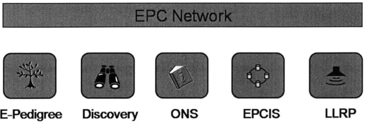
In order to share EPC data among business partners, an agreement has to be reached as to how this information can be communicated. Consequently, a standard was pro-posed in 2005 by the EPC standard body EPCglobal to address this issue. They established an architecture framework to formalize and identify the hardware, soft-ware and data interface components needed to formulate the whole EPC Network [6]. Since then, many standards have been proposed for some of these components. A few of the major ones are illustrated in Figure 1-1.
The functions of each of the components in the EPC Network illustrated above are as follows:
" Electronic Drug Pedigree (E-Pedigree): A historical record that indicates the
chain of custody of a particular drug product being passed from one pharma-ceutical supply-chain partner to another.
" EPC Network Discovery: A system that specifies how EPC-related items can
be visible and accessible within a large network of supply-chain partners. * Object Naming Service (ONS): A name resolution system that specifies how
a Domain Name System (DNS) is used to locate authoritative metadata and services associated with EPCs.
" EPC Information Service (EPCIS): A repository service that allows one to
ture and query EPC-related events generated by readings from RFID Tags and Readers.
9 Lower Level Reader Protocol: An interface protocol that bridges the
communi-cation between RFID Readers and software systems that controls these readers. Currently standards have been proposed and specifications have been derived for all of the components enumerated above with the exception of the EPC Network Discovery. While no discovery standard exists, many designs in this area have been proposed and implemented by research institutions and business corporations. For instance, major players in the software industry such as Oracle and IBM have their own proprietary implementations of the EPC Discovery Service software [1]. Auto-ID Labs at Cambridge University, along with varies industry partners such as Sony and
SAP, has been working on the BRIDGE (Building Radio Frequency Identification
for the Global Environment) project, which attempts to research, develop and im-plement tools to enable the deployment of EPCglobal applications in Europe [14]. A large component of the BRIDGE project is the implementation of an EPC Discov-ery Service. Even within the standard body EPCglobal, detailed propositions on the implementation of discovery services for EPCIS and LLRP have are in the process of being addressed by industry-led work groups.
1.3
Motivations for Implementing E-Pedigree
Dis-covery Service
As the implementations of other components in the network, such as EPCIS and E-Pedigree, become more complete, the Discovery component becomes increasingly indispensable. Currently it poses as the biggest hindrance to the advancement and completion of the EPC Network as a whole. The core component of my research focuses on working with the small building blocks of the discovery problem and ex-perimenting with the various design approaches potentially suitable for the EPC Architecture Framework.
Of the different building blocks of the EPC Network, there are three components
from which a discovery service can be build upon-EPCIS [7], LLRP [8] and E-Pedigree
[9]. A discovery service for EPCIS can be defined as a service that returns event
records associated with a particular EPC from all EPCIS Repositories in the network.
A discovery service for LLRP can be defined as a service that returns RFID Readers
to be controlled by Reader Access Controllers in the network. A discovery service for E-Pedigree can be defined as a service that returns drug pedigree documents associated with certain search criteria.
For this prototype discovery network, the Electronic Drug Pedigree is chosen for a few reasons. For one, there is an urgency in resolving the pharmaceutical prod-uct track-and-trace issue in the health care industry. Government mandates force pharmaceutical companies to generate pedigree documents to be view by the public. This effort in is led by the U.S. Food and Drug Administration (FDA) in attempt to reduce the amount of counterfeiting drugs in the country. Furthermore, from the implementation perspective, Electronic Drug Pedigrees are simple. They are XML documents and do not use special bindings, protocols, and security mechanisms like
EPC Information Systems and LLRP Systems do.
1.4
Thesis Organization
Chapter 2 provides an overview for what an Electronic Drug Pedigree is and how it is used in the pharmaceutical supply-chain industry. Chapter 3 proposes a decentralized design for a pedigree discovery service and demonstrates an implementation of this system. Chapter 4 proposes a centralized approach for the pedigree discovery system and also illustrates a version of the implementation. Chapter 5 compares the two designs presented and discusses the benefits, potential problems, and future work needs to be done for each. Finally, Chapter 6 presents the conclusion of this thesis.
Chapter 2
Overview of Electronic Drug
Pedigree
2.1
Components and Usage
An Electronic Drug Pedigree, or e-pedigree, is a custody record of a particular drug product that is exchanged within a pharmaceutical supply-chain. Although the con-tent of an e-pedigree can vary by law, it is not difficult to derive a standard document format that includes a supper-set of data elements required by all of the laws. Florida is the first state to mandate e-pedigree documents for all drug products originated and handled within the state. Soon after, California joined the effort by making a strict set of pedigree requirements. These laws went into effect January 1st, 2007, and is currently considered the unofficial standard by the pharmaceutical pedigree community [2]. Around the same time in 2007, the Unified Drug Pedigree Coalition work group of EPCglobal ratified a pedigree document format standard [9]. The work group is composed of company representatives from pharmaceutical companies, their industry associations and various US state and federal regulatory agencies. The format was determined to be an XML document. A pedigree document schema that includes all of the necessary data elements were derived as part of the standardization process and the pedigree specification. (An XML schema is a description of an XML document, typically expressed in terms of constraints on the structure and content
e pd e ld."ftecesveda-l w~e0 * ld- , Recekied-
d-wEriahumbe& pedig
V"*tion ShippedPedfgree k-Spe~d1
udte d* doagrn* se"W"mbw temto sedito lot 411011"10#t los. ec n d~ d-' itself.)h 2D m Cp en I-iialy a ay a pdr Stas d
&Unlw (Whoax~~ut Sftute~ppedP@d-2
Figure 2-1: Pedigree Document Layers Generation
of the document, above and beyond the basic syntax constraints imposed by XML itself.)
2.1.1
Document Components and Layout
Initially, a pedigree contains drug product information only. As the corresponding drug product moves from one supply-chain partner to another, new layers of the pedigree are added each time to record the business transaction information. Each new layer of the pedigree wraps around an older layer. The more the number of business transactions carried out on a product, the more the number of layers of the associated pedigree document. Figure 2-1 is an example of the pedigree formation process.
When a new layer is added to a pedigree, it often requires the business partner cre-ating the layer to apply a digital signature to authenticate all information contained, including previous layers created by other supply-chain partners. The details of the signing process is explained in Section 2.2. Of the five different types of pedigree layers can be used in a pedigree document, two requires signing. The definition of
the five layer types are shown below:
" Initial Pedigree: The innermost layer of the pedigree document that records
initial product and packaging information of a particular drug product.
* Repackaged Pedigree: The innermost layer of the pedigree document that not only records product and packaging information of a particular drug product but also records the information of the previous products and pedigrees used in the new product.
" Shipped Pedigree: An outer layer of the pedigree document that records the
business transaction information for a product that is ready to be shipped to the next supply-chain location. This layer can be used to wrap any of the other
four pedigree layers and requires a digital signature of the shipping party. * Received Pedigree: An outer layer of the pedigree document that records the
business transaction information for a product that has been received from a previous supply-chain location. This layer can be used to wrap the Shipped Pedigree layer and requires a digital signature of the receiving party.
" Unsigned Received Pedigree: An intermediate layer of the pedigree document
that records the business transaction information for a product that has been received from a previous supply-chain location. This layer can be used to wrap Shipped Pedigree layers and, as the name suggest, does not require a digital signature. (This layer must be generated concurrently with a wrapping Shipped Pedigree layer).
2.1.2
Business Flow Scenarios
There are twelve types of business flow scenarios in which a pedigree document can be used. For the purpose of this Thesis, I will not iterate each one but will simply show two examples to illustrate how pedigrees are used under different business contexts. The most common business flow scenario is the transaction from a manufacturer, to
a wholesaler, then to a retailer. A manufacture can initiate an Initial Pedigree layer and adds a Shipping Pedigree layer to the document when the product is ready to be transferred to the wholesaler, with signature applied. Once a wholesaler receives the pedigree and the associated drug products, the wholesaler would authenticate the information presented in the pedigree as well as the digital signature. When all information are authenticated, a Received Pedigree layer is added to the document and signed by the wholesaler. The process repeats as the pedigree moves from the wholesaler to the retailer. Figure 2-1 shown above is an example of this scenario.
Not all transactions has to originate from a manufacture. Sometimes a whole-saler can initiate a pedigree on behalf of the manufacture. The original transaction information from the manufacture to the wholesaler would simply be recorded inside an Initial Pedigree or a Repackaged Pedigree layer. For instance, a wholesaler can initiate a pedigree to indicate a return transaction to a kit manufacture. Initially the wholesaler creates a Repackaged Pedigree to indicate the previous product and previ-ous pedigree information for each drug contained in the kit. Then it adds and signs a Shipped Pedigree layer for the return transaction. If the wholesaler decides to sale the same product to another retailer, it would add another receiving and shipping layer on to the current shipping layer. However, if both layers were to be added at the same time, the process can be simplified by replacing the Received Pedigree layer with the Unsigned Received Pedigree layer, so that only the outermost Shipped Pedigree layer has to be signed. Figure 2-2 shown below is an example of this scenario.
Regards of the business scenario, all pedigrees have to abide by the rules shown in Figure 2-3 when new layers are generated. Pedigree layers with solid arrows pro-jecting out indicate that they cannot be stand-alone and must have additional layers wrapping around them. Layers with dashed arrows indicate that they can be stand-alone, and any additional layers are optional.
igre 2-:PeegedLyrieertrnFewDaga
Asmetine arie, hppd~dire ndeeiePedigree
eeet
eur
sigin; hnc aSigatreeleen mst e ppnde. Uhesign
ehns
pediree ocumnt
snderto te doumendregrver
A siger'sur ey 2-3su: l P medd aer Gentherati at that Disrattm eth
pedgre Documen he
uthewng
caigrssonxm
etfctedt
Fgr
-)
Theing encue aSiwste eeert t frms be GaphpesnUer ITeraenhe rinnmcaight seos thli ey ame rctr PI)aogwihX0 certificates [17] User daaerrtrifaWidwsC-se
2.2.s aemddita Signature Uelmnsadaextcedurgthsiaue
atetctoprcs.The following flgur (Figuer2-6 illustrates the inn n uhiai process o peif e PKI. unt signdeg potessoaumessag digstiver. temsaecotn en
siged les figrsowstd.Te the ignrssitcPate KrmaGapisUey Itersignover the digst.
Figure 2-4: Pedigree Authentication Process
Figure 2-5: Example Certificate Data
Fleid Vake
-gnature aldnthM sh1a1RSA
Issuer TCR11
vaid from Tuesday, Aprf 17, 2007
vabdto S*turday, Decenber 31,
5ubject TCRI1
P-bbO eey RSA (1024 Bts)
Au ty Key Identier Key-6 63 9tca 6c .
-Ix, n
LeaM mm e about r
St.12:...
2.M...
Validating Message
Message .. I am a cat
I am a cat
u.. decaypsignature
Digest ... #@ic(#:9d msa
#@jc(#V:9d Enryptdigestwith Digest #@c(#:9d Digital Signature I am a cat
Figure 2-6: Use of Public Key Infrastructure
Key to decrypt the signature to obtain the original digest. Then the authenticator would compute another digest of the message content and compare the two. If they match, one can guarantee that the content of the message has not been tampered with after it is signed. For drug pedigree documents, message digests are computed using the SHA1 algorithm, and digital signatures are computed using the RSA algorithm.
2.2.2 X509 Certificate Usage
Digital signatures only guarantee that a signed pedigree has not been not tampered with but does not guarantee the identity of the signer; thus X509 certificates are used to bind a public-private key pair to the signer's identity. Some of the components of
a certificates include validity period, serial number, issuer name, subject (user) name,
and user public key [17]. To verify that the Public Key belongs to the signer, the authenticator must already have a trusting relationship with the Certificate Authority
(<:Signature> <k:Signedlnfo>
K :Canonicalizati rilethod Aigoll= t1YvWY3 or1Q1I/z-~-~0 />
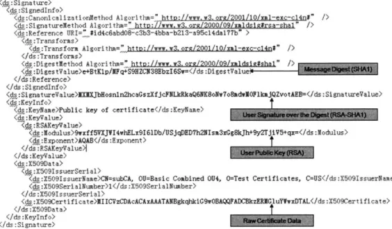
(a:Signatxre~ethod Aigoth:_ -ttp sgfs-hl (,ds:Reference 'URI="#id4c6abd8-c3b3-4bba-b23-a95c14da177b" > (da :Transforas> <f:Transforn Algoritha=".httn://www.v3.org/2001/i1ixal-exc-cl4n$" /> </ds:Transfors> <s:Digestlethod Algoritha=" /> <ds:DigestVaue>e+BtK1p/XFq+S9HZCN38EbzI6Sw</ds:DigestValu a -</di :Reference> </ds:SignedInfo> <(d:SignatureValue>IXlIJbHosnin2hcaGszXfjcFNLkRaQ6NK8oNw7o8adwOFkajQZvotAEB=</ds:SignatureValue> <ds:KeyInf>
<:KeyName>PubIic key of certificate</ds:KeyNaxe> <k:KeyVaiue> <k:RSAKeyValue> <ds :odulus>9wxff5VXJVI4whELx9I6lDb/USjqDED7h2NIsa3xGg8kJh+9y2TJiV5+qx=</ds:1odulus> <ds:Exponent>AQAB</ds:gxponent> </ds:RSAKeyValue> </ds:KeyValue> <O:X509Data> <5:X509IssuerSeria>
<&_:X509IssuerNaae>CN=subCA, OU=Basic Coabined OU4, O=Test Certificates, C=US</ds:X509IssuerNaxe> <S :X509SerialNwmber>i</ds:X509SerialNuaber> </ds:X509IssuerSerial> <(:X509Certificate>IIICVzCDAcACAxAAATANBgkqhkiG9v0BAQQFADCBkzERIGluYYvxDTAL</ds :X509Certificate> </ds:X509Data> </ds:KeyInfo> </ds:Signature>
Figure 2-7: Signature Element of a Pedigree Document
(CA) that issues the signer's certificate. In other words, he or she must have CA's
Public Key. The certificate itself contains a digital signature, signed over the user Public Key using the CA's Private Key. The authenticator can use the CA's Public Key to verify the CA's signature over the user Public Key. Once it is clear that the user Public Key belongs to the signer, the authenticator can use the key to verify the pedigree content. An example Signature element of a pedigree document is shown below in 2-7. This XML block of document not only includes the certificate itself but also the transforms, canonicalization, and signature methods used to compute the digest and the digital signature value.
2.2.3
Common Registry
Although digital signatures and X509 certificates can be used to guarantee the au-thenticity of pedigree content and the identity of the signer, it does not prevent the signer to change the content of the pedigree and re-sign at a later time. Currently, all pedigree documents are maintained and stored locally by the individual businesses that have created these documents. Thus a prevention scheme may be necessary to prohibit companies from potentially manipulating their information. Many industry
participants have been actively promoting the use of a common registry. Currently the structure of the registry has not been finalized. It may be historical copies of all drug pedigree document exchanged within the entire supply-chain, or it may simply be a hash, or digest, of the documents. Many large companies, such as Verisign, have been competing for the position as the primary holder of the common registry. However, whether this registry is needed at all is still uncertain.
Chapter 3
A Decentralized Approach to
E-Pedigree Discovery Service
3.1
Previous Work
3.1.1
Design Motivation
The purpose of a pedigree discovery service is to provide searching assistance for pedigree documents that reside on the EPC Network. A decentralized approach to discovery suggests that all pedigree documents associated with a particular business must be maintained in its local repository. This approach may be preferred from a business logistric's point of view. For one, pharmaceudical companies might be skeptical and reluctant to actively report their data into a centralized location for others to manage. In addition, if mistakes need to be revised, the revision process can be performed must faster if all data are maintained locally, thus reducing business costs. From the point of view of system design, a decentralized service reduces the possibility of potentially having a message loading bottleneck at the central storage server and having a single point of failure if the server breaks.
3.1.2
Existing Discovery Protocols
Many common discovery protocols were surveyed for the purpose of this design, in-cluding Jini [18], Salutation [4], UPnp [5], SLP [15], and UDDI [10]. However, all current protocols lack one important parallelism with what is needed for the Pedi-gree Discovery Service-All the discovery protocols enumerated above looks for any
one service that would satisfy a client's needs, but a discovery service on the EPC
network requires all services that satisfy the client's needs. Currently there is no available framework that fully implements the latter. The services that are close to satisfying this need are search engines like Google.
3.1.3
Overview of Salutation
Of all the discovery protocols mentioned above, the one that influenced the design
pre-sented in this Chapter the most is Salutation, developed by Salutation Consortium. It is also the only one that uses a decentralized network approach. The architec-ture of Salutation is composed of three fundamental components: Functional Units, Salutation Managers, and Transport Managers. Multiple clients and services can be attached to one Functional Unit, and Functional Units can communicate with each other about the services that they provide. A client only needs to connect to one unit to locate a desired service in the network.
Each Functional Unit contains a Salutation Manager and a Transport Manager. Salutation Managers serve as service brokers that 1) help clients to find desired ser-vices and 2) allow serser-vices to register their availability. They communicate with each other through remote procedure calls (RPC). Transport Managers isolate the detailed network specific protocol information from Salutation Managers, thereby giving Salu-tation network transport independence. Figure 3-1 is an overview of SaluSalu-tation's architecture.
Client
Service Service
Service
Client-
Client
Salutation
Manager
RPC
Salutation Manager
Trans
Transport
Manager
Figure 3-1: Architecture of Salutation
3.2
Design Architecture
3.2.1
Design Assumptions
In order to scale the prototype to contain only the minimum crucial portions of the design, many important assumptions were made. For one, since the design does not contain any security mechanism, it is assumed that all the service partners in the network may freely access each other's data. In addition, it is assumed that business relationships do not form and discontinue frequently. Thus, the overturn rate of businesses entering and leaving the network is low. For the initial implementation of this design, there is no mechanism that supports automatic registration of business partners. In addition, the total number of partners participating in the network must be scalable such that there are no significant delays caused by querying a large number of partners in the network. Finally, we assume that having stale data, caused
by delays in content refreshing in local servers, is allowed.
3.2.2
Architecture Overview
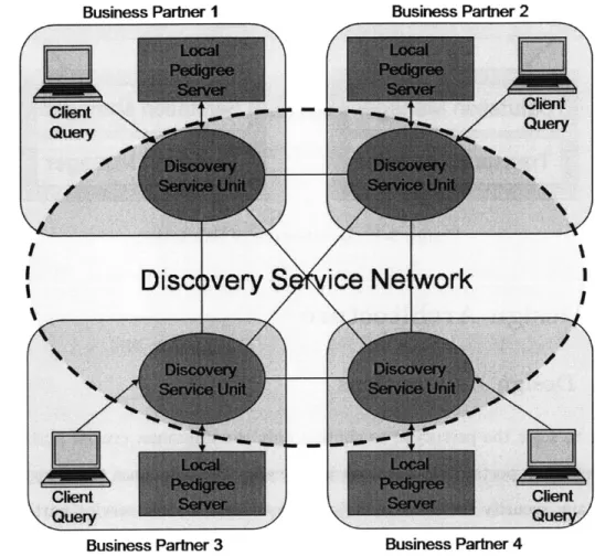
The decentralized pedigree discovery service is defined as a network of services that returns a list of pedigree documents associated with a common attribute for which a client has used as searching criteria. A client can be a company, a consumer, or a government agency. This network is composed of identical service units, which serve a similar purpose as Functional Units in Salutation. These units, referred to as a
Business Partner 2
Business Partner 3 Business Partner 4
Figure 3-2: Pedigree Discovery Service Network
Discovery Service Units, reside locally with individual business partners. They are directly attached to local pedigree servers where pedigree documents are stored. A service unit has two purposes: 1) extract metadata from pedigree documents residing in local servers, and 2) answer client queries by communicating with a predefined list of service units to obtain pedigree documents. A service unit would always be connected to one or more other service units, and these interweaving connections form the Discovery Service Network. Figure 3-2 illustrates an overview of this network.
3.2.3
Network Communication
As mentioned above, a Discovery Service Unit has two functions, thus two design components. Just as there is a layer of separation between a Salutation Manager
Pedigree Server 1
0 Local LookUD Unit
24983 (A 95783 49853 D C: Un I ocal Look 247,r 351 9 487r,
S
ocal Lookup Unit48305 0
12345 0
98244 0
Pedigree Pedigree Pedigree
Server 2 Server 3 Server 4
Figure 3-3: Communication among Discovery Service Units
and a Transport Manager in Salutation, there is complete isolation between the two major components that make up a Discovery Service Unit: the Partner Lookup Unit and the Local Lookup Unit. The Partner Lookup Unit accepts client queries and conducts searchs of pedigree documents that match client requests by communicat-ing with other Discovery Service Units. The Local Lookup Unit accepts queries from Partner Lookup Units of other service units and locally searches its metadata in at-tempt to match client requests. Figure 3-3 is an example of how partner Discovery Service Units interact with each other. For explanation purposes, the metadata used in answering client queries are pedigree serial numbers. In reality, many different pedi-gree document attributes can be used as metadata beyond the simple serial number caching presented in the figure.
In a Discovery Service Unit, a Local Lookup Unit may contain a list of serial numbers referring to all pedigree documents residing in the local server. When a client queries for pedigree documents with specified serial numbers, the Partner Lookup Unit searches its local server as well as the Local Lookup Units of other Discovery Service Units. Once a client query reaches another service unit, it is forward onto other
Discovery Service Network
Local Lookup Service Interface
Company
Registry Query
Processing Serial Number
Results Unit Lookup Table
Cache
Partner Lookup Service Interface
Clients Local Pedigree Server
Figure 3-4: Discovery Service Unit Architecture
Discovery Service Units known by the current service, and the process continues. The above figure illustrates this principal. For instance, the client is connected to
Unit 1, which is connected to Unit 2 and 3. But since Unit 3 is connected to Unit 4, the client query is forwarded onto Unit 4, which communicates with Unit 1 to answer the query. It is worthy to note that a service unit may refuse to forward a client query
if the Time to Live (TTL) value of the query has been expired.
3.2.4
Design Components
This section describes in detail the design of the two components of the Discovery Service Unit. Figure 3-4 provides the layout of a typical Discovery Service Unit. Again, for explanation purposes, only pedigree serial numbers are mentioned instead of other pedigree attributes.
The Local Lookup Unit contains a Lookup Table composed of serial numbers and file location pointers. The table is updated as new pedigree documents are submitted to the local server. When a client request asking for documents with a particular
serial number is received, the Local Lookup Unit searches its Lookup Table, if the serial number exists, it retrieves the corresponding pedigree documents from its local server and forwards the query onto the Partner Lookup Unit. The Partner Lookup Unit would then forward the client query onto other Discovery Service Units, but only if the query's TTL has not yet been expired. The average pedigree document is usually associated with three businesses-such as a manufacture, a wholesaler, and a retailer; therefore a TTL value that permits the query to be sent to Discovery Service Units that are four degrees removed would be sufficient. Of course, this assumes that the client would have some justification for choosing the initial entry point where the query is made. However, this assumption may be dangerous. Choosing TTL values itself can be a challenging optimization problem, which I will discuss further in Section 5.2 of Chapter 5.
The Partner Lookup Unit is composed of a Partner Registry, a Results Cache and a Query Processing Unit. The Partner Registry contains a list of endpoints, or URLs, of each Discovery Unit known by the current unit. (In most situations, this list would contain Discovery Service Units that belong to frequent business partners.) The Results Cache contains query results that are recently returned by the network. When a client queries the Partner Lookup Unit, the service would first check with the Results Cache, and remote queries to partner Discovery Units are only made if the result is not already available in the cache. All cache results are kept for a predefined period of time, which may vary depending on network traffic. If the cache is full, it would function as a First In First Out (FIFO) queue. The Query Processing Unit handles the actual queries that flow through the network. When a query originated from a remote discovery service is being forwarded to another service, the Query Processing Unit sets its return address to that of the original service unit where the query is initiated, so results can be returned directly. As results come back from the network, (which do not have to be in the same order as it is sent out,) the Query Processing Unit packages them and returns them to the client.
3.3
Web Service Implementation
3.3.1
Implementation Overview
As mentioned earlier, pedigree metadata are extracted while files are being stored into local servers. These characteristic data may include serial number, drug name, business names, and other XML elements of a pedigree document. Clients may use any of these data fields as query parameters in their search. Again, for demonstra-tion purposes, the implementademonstra-tion only considers pedigree serial number as a query parameter. Nonetheless, regardless of the query parameter used for searching, the process for how queries are performed remains the same.
The Discovery Service Unit is implemented using .NET technology as a set of two separated Web Services with different port locations. One implements the Partner Lookup Unit and the other the Local Lookup Unit. Each service contains only one method, which takes in a serial number as its input parameter and performed all the necessary processing for results to be returned. The service interface for each of the two services is shown below:
[ServiceContract]
public interface ILocalLookupService
{
[OperationContract]
XmlDocument[] GetLocalData(Serial serial); }
and
[ServiceContract]
public interface IPartnerLookupService {
[OperationContract]
XmlDocument[] GetPartnerData(Serial serial); }
The method GetLocalData takes in a serial number of user defined type Serial and searches its local Lookup Table, implemented as a DataTable object. If there is
a match, it retrieves and returns pedigree documents in the format of XmlDocument arrays. Similarly, The method GetPartnerData also takes in a serial number of type Serial, sends a request to every Discovery Service Unit listed in the Partner Registry, and records the results in Results Cache before returning it to the client as XmlDocument arrays. The Partner Registry and Results Cache are also implemented as DataTable objects.
Windows Foundation Communication (WFC) is used, and both the
ILocalLookupService and the IPartnerLookupService are self-hosted by perform-ing the followperform-ing:
ServiceHost host = new ServiceHost(typeof(LocalLookupService), baseURI);
host. OpenO;
and
ServiceHost host = new ServiceHost(typeof(PartnerLookupService), baseURI);
host.OpenO;
The LocalLookupService and PartnerLookupService inherit from the
ILocalLookupService and IPartnerLookupService base class, respectively, and these services implement the logic behind the interfaces. The baseURI is a string
that indicates the URL endpoint of the service.
When a Local Lookup service host opens, the Lookup Table is uploaded from local memory and updated as new pedigree documents are inserted or deleted from the local pedigree server. Uploading and deletion of data are performed atomically to prevent data inconsistency. When a Partner Lookup service host opens, its Partner Registry is loaded from memory and an empty Results Cache is created. The cache is gradually filled as client queries are processed. Again, this operation is performed atomically. Furthermore, since all results are stored in one instance of the cache, only
one instance of the service is created. All clients connect to the same instance. This is made possible by using WFC, which differs from a typical Web Service, where an instance is created for every client and discards after use. A WFC service remains alive as long as the host is open.
[ServiceBehavior (InstanceContextMode = InstanceContextMode.Single,
ConcurrencyMode = ConcurrencyMode.Multiple)]
In addition, to improve performance, requests sent to remote discovery units are
made asynchronously, so as results come back (possibly in different order than it is being sent out), it can be assembled right away to be sent back to the client. A timer is set for each request so that the service does not wait forever for a response to comeback. Consequently, if certain remote services fails to respond, partial results can still be returned. The following code is taken from the Query Processing Unit, where queries are been sent out asynchronously to the Local Lookup Unit of another Discovery Service Unit:
ServiceEndpoint httpEndpoint = new ServiceEndpoint(
ContractDescription.GetContract(typeof(ILocalLookupService)), new WSHttpBindingo, new EndpointAddress(url));
ChannelFactory<ILocalLookupService> factory =
new ChannelFactory<ILocalLookupService>(httpEndpoint);
ILocalLookupService svc = factory.CreateChannel();
IAsyncResult ar = svc.BeginGetLocalData(serial, null, null);
First, a ServiceEndpoint object is created to specify 1) the contract of the service
ILocalLookupService and 2) the location of the service indicated by the url string.
Then, the ChannelFactory creates an instance of ILocalLookupService, which calls BeginGetLocalData (instead of the normal synchronous method GetLocalData) to send a request to another Discovery Service Unit. Again, this method take in a
serial number of type Serial. As results come back, they are contained in the IAsyncResult object and can be retrieved by performing the following:
XmlDocument[] result = svc.EndGetLocalData(ar);
The ILocalLookupService calls EndGetLocalData, which takes in the
IAsyncResult object and return the actual pedigree documents in XmlDocument
ar-ray form.
3.3.2
The LocalLookupService Object
As mentioned earlier, the LocalLookupService takes in a serial number of type Serial and searches through its Lookup Table for a match. If a match exists, then it retrieves the corresponding pedigrees from the local server. This process is embedded in the method GetLocalData of class LocalLookupService. A section of this method is shown below:
DataTable table = LocalUnitHost.SerialLookUp.SerialTable;
DataRow row = table.Rows.Find(serial.Value);
XmlDocument[] result = null;
if (row != null) result = UtilitiesLocal.RetrivePedigrees(row);
The Lookup Table, called SerialTable is instantiated in the
LocalLookupService host class LocalUnitHost. It contains two columns: 1)
the serial number of type Serial and 2) the pointers to the corresponding
pedi-gree file locations of type string [. The Value property of the Serial object
contains the actual serial number to be searched. If during the querying process a corresponding entry is found in the table, the helper method RetrivePedigrees would use the pointers to retrieve the pedigree documents from the server. In the current implementation, a separate program is in charge of filtering information from captured pedigrees and updating the Lookup Table. The current program only reloads the table from memory periodically, such as shown below:
if (TimeToReloadO)
{
Thread thread = new Thread(new ThreadStart(UpdateTable));
thread.IsBackground = true;
thread. Start 0
}
The TimeToReload method is set to true periodically, which spins out a (Thread) that updates the Lookup Table. The UpdateTable method simply loads the newly
revised table from memory and merges the two tables.
DataTable newTable = UtilitiesLocal.LoadMyTable(FileLocation);
DataTable table = LocalUnitHost.SerialLookUp.SerialTable;
table.Merge(newTable, false);
The FileLocation parameter indicates the location of the Lookup Table in
mem-ory. Having the second parameter of the Merge method set to false guarantees that
in case of conflict, incoming values can overwrite existing values in the table.
3.3.3
The PartnerLookupService Object
The PartnerLookupService answers client requests by forwarding the request onto Discovery Service Units listed in the Partner Registry. The query is sent out to the network through the Query Processing Unit if it is not found in Results Cache. This entire process is encapsulated in one method, called GetPartnerData, in the PartnerLookupService class. A section of this method is shown below:
DataTable rsltsTable = PartnerUnitHost.rsltsCache.ResultsTable;
DataRow row = rsltsTable.Rows.Find(serial);
if (row != null)
return UtilitiesPartner.BuildResults(row); }
else
QueryProcessingUnit myQuery = new QueryProcessingUnit (serial);
return myQuery.ExcuteQueryo;
}
The method first checks the Results Cache, which is instantiated by the service
host PartnerUnitHost. The cache ResultsTable is stored as a DataTable object. It has two columns: 1) The serial number of type Serial, 2) the previously returned
pedigree results of type XmlDocument []. If the query is found in the cache, the
pre-viously stored results would be returned by BuildResults; otherwise an instance of QueryProcessingUnit is created to send the search request out to the network. In
order to send a query, the ExcuteQuery method must first obtain the URLs of its
part-ner services from the Partpart-ner Registry. It then sends the request out asynchronously to Local Lookup Units of partner Discovery Service Unit, shown below:
DataTable registry = PartnerUnitHost.ptnerReg.RegistryTable;
ArrayList returnedRslts = new ArrayListO;
foreach (DataRow row in registry.Rows) {
XmlDocument[1 result = UtilitiesPartner.SendRequest(row);
returnedRslts .AddRange (result);
}
XmlDocument [1 results = (XmlDocument []) returnedRslts .ToArrayO;
UtilitiesPartner.CacheInsert(serial, results); return results;
Like the Results Ccache, the Partner Registry RegistryTable is also instanti-ated by the service host PartnerUnitHost. Client requests are sent out one-by-one asynchronously to partner service units through the method SendRequest. This asyn-chronous process is described in the above Section 3.3.1. As results come back from
the network, they are compiled into one arraylist named returnedRslts. Before results are returned, it is inserted into the cache by the CacheInsert method.
3.3.4
The PartnerLookupService Client
Anyone who wishes to utilize the discovery service can connect to the Partner Lookup Unit of a Discovery Service Unit. However, he or she would first need to build a service proxy for the PartnerLookupService and then connect to the proxy. For example, if a client wants to obtain all pedigree documents containing the serial number 12345, he or she would run the following program:
PartnerLookupServiceClient client = new PartnerLookupServiceClient();
DiscoveryServiceUnit.Serial serial = new DiscoveryServiceUnit.Serial();
serial.Value = "12345";
XmlDocuments [ resultPedigrees = client.GetPartnerData(serial);
The PartnerLookupServiceClient object, provided automatically by the proxy, allows the client to directly utilize the web service method GetPartnerData. The ser-vice endpoints are specified in a separate configuration file app. conf ig. The following is a section of this file:
<client> <endpoint address="http://localhost:9000/PartnerLookupService" binding="wsHttpBinding" bindingConfiguration="WSHttpBindingIPartnerLookupService" contract="IPartnerLookupService" name="WSHttpBindingIPartnerLookupService"> <identity> <userPrincipalName value="AUTO-A2F185FFE5\Indy" /> </identity> </endpoint> </client>
Chapter 4
A Centralized Approach to
E-Pedigree Discovery Service
4.1
Previous Work
4.1.1
Design Motivation
A decentralized approach to electronic pedigree discovery service allows pedigree
doc-uments to be managed by individual supply-chain partners. However, this approach forces a client to wait for search results from multiply locations and is greatly depen-dent on network performance. A centralized approach, on the contrary, uses a much simpler search process. It simply requires a search to be conducted on the local file system. There would be no need to send search request out to the Internet, hence query performance can be greatly improved.
Furthermore, performing data search in local memory is a more manageable prob-lem than architecting new network discovery protocols. Much research has been performed in this area. In this approach, the problem becomes 1) designing a search engine of high performance and 2) effectively managing large amounts of data. An example solution to the first problem is the Google File System [11]. An example solu-tion to the second problem is the Google's BigTable, which implements a distributed storage system [3]. Another solution can be a distributed in-memory database
pro-<Channel>
<---,le>Lio Nwews</title>
<,:.rnk>*-ttp://1 if toff .=zic.nasa.qcv/</!..4k>
<de-t,n>cftoff -c Space Exploratn. </desorp tc-.>
<Iang age>en-us</Ianguage>
<pubDate>Tue, 10 Cu- 2-n3 :: <
<-ast~u-,1dDate>TUe, - :u= 2n- 9:--5Sr<lstuldae
<dccs>ttp://lgs.Ia.araredu/tecfrss</doos>
<generator>7 ebbog Edror 2.D</generator>
<rAnag ingid::. -or> ed i,:zr e xamp.e -c =< /ma naging--d;.t-r>
<wbate omatrexml~om</web. aster>
<otte>3tar City<tte
<!I-k>'ttp://iftoff.msfc.nasa.qv/ne'ws/2 3/news-szarcity.asp</llnk>
<desCript1:on>Hcw do Americans get ready to work with Russ.ans aboard the
IcerrnatSona 3paoe c Station? They take a crash course in culture, ianguage
and procol at Russia's Star Cicy.</desoription>
<putDate>T,e, *Jun 203 O9:39:21 CT</pubDace>
<gu:>ht-p://fccff.mcasa.g'/2../M/2.tml*:em% <guid> </ tem
<1tcem>
<lIk>htc :l'Ifof-msc.nasa.gov new/2003/ne's-Iaundry.as</2.nk>
<description>C mpared to earL'er spacecraft, che International Space Station has many luxurles, but laundry facilities are not one of them.
Znstead, astronauts have other opti.:ns.<ldescri pson>
<pubDate>Tue, 20 May 2273 .!:5f:2 *[ </ubDaZe>
Figure 4-1: Example RSS Feed
posed by MIT Auto-ID Labs [16].
4.1.2
Overview of RSS
The centralized approach uses the Really Simple Synchronization (RSS) framework to capture and manage pedigree documents [20]. RSS forms a standard way to publish frequently updated digital content. Its most common application is in publishing of news blogs. A RSS Feed is analogous to a table of contents. Each entry in the Feed summarizes the content of some information located elsewhere and provides a link to the full content. RSS formats are specified in XML. Figure 4-1 illustrates a typical RSS feed.
Recently many extensions have been developed to support the use of RSS in different context. The extensions are predefined XML elements that fall under a
different namespace than that of the default namespace. The minimum requirement for an RSS entry, or an <item>, to be valid must include the following fields:
" Title
" Description
" Link
If extension elements are used, they are appended to the required elements
and are child nodes of <item>. For instance, an extension to Yahoo! Weather feeds would include elements such as <yweather: location>, <yweather: wind>, and <yweather: atmosphere>, under predefined namespace yweather.
For the centralized e-pedigree discovery service, RSS is used along with the Google Base extension fields under the namespace g and gbase. This framework serves as the backbone to metadata storage of pedigree information, where characteristic attributes for each pedigree document is extracted and saved as an RSS entry in Google Base.
4.1.3
Overview of Google Base
Google Base allows Google account users to freely publish RSS feeds under their own accounts for the public to browse. The information posted by the public can be informational, such as recipes and personal profiles, or commercial, such as housing and products for sale. The following is an example RSS entry found on the website:
All items published are accessible through the use of the Google Query Language
[12]. For instance, if one wants to search for a digital camera that is under $500, he or she perhaps would construct a query like the one shown below:
digital camera [price <= 500.0 USD1
A matching entry would contain the phrase digital camera in the <title> or
<content> field, and it would also contains a field <g: price> whose value is less than
<entry>
<id>http://wvv.google.com/baae/feeds/anippets/9026918904664888476</id>
<published>2007-05-26TO3:03:08.000Z</publiAhed> <updated>2007-05-29T04:47:14.000Z</updated>
<category schee- http://base.google.cow/categories/itemtypes term-IProducts'></category> <title type-' text '>Canon Powershot 5D550 Digital Camera Battery Door</title>
<content type- htol'>SquareTrade A. AP6.0 Please Read Entire Description Before Bidding or guying.Item Description: This is a <link rel-'alternate' type-' text/html' hret- http://ed:arm.meditplex.co/ad/ck/711-5256-e19g-2?1oa-http;3kk2F,2Fagi.ebay.con*2
<link rel-self' type- application/ato+xml' href-'http://wvw.google.co/base/feeds/snippets/9026618904664888476'></1ia>
<author> <name>eBay</name>
<email>rcross@ebay.com</ef.ail>
</author>
<g:brand type- text' >Digital Camera Battery</g!ibrand> <g:item type type- text'>Products</g:item type>
<g:item language type' text'>EN</g:itemlanguage> <g:price type-'floatUnit'>9.95 usd</g:price> <g:target country type- text '>US</g: targetcountry>
<g:image link type-' urI'>http://thurbs.ebaytatic.com/pict/i4IZ2326763_1.jpg</g:maglink> <g:category type-,text'>Caweras 4amp; Photokgt;Digital Caerastgt;Parts & Repair</g:category> <g:ustomer id type- int'>11729</g:customerid>
<g:id type-' text' >140122326793</g:id>
<g: expiration date type-' dateTime' >2007-06-25T03 :03:09. OOOZ</g: expiration date>
</entry>
Figure 4-2: Example Google Base Entry
To further assist users, a programming API for Google Base was developed [13]. The GData API not only allows Google Base users to programmatically create, revise, delete their own items in Google Base but also provides a channel for users to search for publish items that can automatically be fed into user applications. Client libraries are available in C# and Java. For this implementation, the C# libraries were used along with ASP.NET to construct the Web Service framework described in Section 4.3.
4.2
Design Architecture
4.2.1
Design Assumptions
This design assumes that all pedigree documents submitted to the central pedigree server satisfies the standard document format stated in the Pedigree Ratified
Stan-dard v1.O
[9],
so that XML elements, or pedigree data fields, can be extracted touse as metadata. In addition, this design does not involve the use of any security mechanism. As stated earlier, pedigree documents by law must be open to the pub-lic. Furthermore, this design requires a constant connection to Google Base servers. Although in the future a separate search engine will be built, the current implemen-tation relies heavily on Google Base to perform the search of pedigree documents. Finally, and most importantly, this design only attempts to solve the data discovery
Base
BETAC
-Serial number C
-Drug name t
---> -Manufacture Server Records 2c:
-Etc. .0
1 0
0
I Pedigree Metadata
Pedigree Documents
Figure 4-3: Pedigree Capture Process Flow Diagram
problem and does not propose a solution for the data storage problem. Hence, it is assumed that the central pedigree server has the memory capacity to store all the pedigree documents submitted to the server.
4.2.2
E-Pedigree Capture Process
The centralized pedigree discovery service can be broken down into two parts: Cap-ture and Query. The pedigree capturing process is shown in the following figure.
As a pedigree document is submitted to the server, it is filtered to extract char-acteristic data. The data fields, or XML elements, extracted are the fields that are most representative of and whose values are the most unique to the pedigree docu-ments that contains them. This metadata information is pushed onto Google Base as an <item> of a RSS feed, The full document is stored in the local file system. It is important to note that each entry fed to Google Base not only includes the metadata but also the pointer to the file location in the server, so one can effectively retrieve desired documents after matching metadata are found as a result of a client query.
-Serial number = 12345
-Drug name = Product A
-Fie Location= C//Pegrees/doc83742.mi -Etc.
Matching E-Pedigree Server Records Matching Metadata
Figure 4-4: Pedigree Query Process Flow Diagram
4.2.3
E-Pedigree Query Process
An example pedigree querying process is shown below in Figure 4-4. For instance, if a client wants to obtain all pedigree documents containing the serial number 12345, the discovery service application would submit a query to Google Base, and Google Base would return all RSS entries with the serialNumber=12345. For each entry that is matched, the service application would use the corresponding file path, such as f ileLocation=C: //Pedigrees/doc83742.xml, to obtain the matched documents in the server. These documents are then returned to the client.
4.3
Web Service Implementation
4.3.1
Implementation Overview
Same as the decentralized discovery service implementation, the centralized version also uses .NET technology and the Web Services framework. The following figure is a screen capture of this service shown in a web browser.
As shown above, the web service only supports two web methods:
PedigreeCapture and PedigreeQuery. The following code is a stripped-down ver-sion of this service.
Search Engine
A web service that allows one to upload and search for e-pedigree documents.
The following operations are supported. For a formal definition, please review the Service Qescription.
* PedioreeCaDture
* PedigreeQuery
0 Find: price j Next 4 Previous -j Highlight all 1 Match case
http:/localhost:50330/PedigreeServer/Service.asmx?op=PedigreeQuery
Figure 4-5: Screen Capture of Web Service Interface
[WebService(Namespace = "PedigreeServer",
Description = "<b>A web service that allows one to upload
and search for e-pedigree documents.</b>")]
[WebServiceBinding(ConformsTo = WsiProfiles.BasicProfilel_1)]
public class PedigreeService : System.Web.Services.WebService
{
[WebMethod]
public void PedigreeCapture(XmlDocument pedigree, string filename) {
PedigreeCapture capture = new PedigreeCapture(pedigree, filename);
capture.StorePedigree();
}
[WebMethod]
public XmlDocument [] PedigreeQuery(XmlDocument queryDoc)
{
PedigreeQuery query = new PedigreeQuery(queryDoc);
return query.Runo;