Comparing directed efficiency of
III-nitride nanowire light-emitting diodes
The MIT Faculty has made this article openly available.
Please share
how this access benefits you. Your story matters.
Citation
Chesin, Jordan, and Silvija Gradecak. “Comparing Directed
Efficiency of III-Nitride Nanowire Light-Emitting Diodes.” J.
Nanophoton 8, no. 1 (February 13, 2014): 083095. © 2014 Society of
Photo-Optical Instrumentation Engineers (SPIE)
As Published
http://dx.doi.org/10.1117/1.jnp.8.083095
Publisher
SPIE
Version
Final published version
Citable link
http://hdl.handle.net/1721.1/87660
Terms of Use
Article is made available in accordance with the publisher's
policy and may be subject to US copyright law. Please refer to the
publisher's site for terms of use.
Comparing directed efficiency of
III-nitride nanowire light-emitting diodes
Jordan Chesin
Silvija Grade
čak
Comparing directed efficiency of III-nitride
nanowire light-emitting diodes
Jordan Chesin and Silvija Grade
čak
*
Massachusetts Institute of Technology, Department of Materials Science and Engineering, 77 Massachusetts Avenue, Cambridge, Massachusetts 02139
Abstract.III-nitride-based nanowires are a promising platform for solid-state lighting. III-nitride nanowires that act as natural waveguides to enhance directed extraction have previously been shown to be free of extended defects even on foreign substrates, such as silicon. While the effi-ciency of nanowire-based light-emitting diodes (LEDs) has been investigated, there has yet to be a comparison of heterostructures based on nanowires grown in different crystallographic direc-tions. We compared the directed external quantum efficiency (EQE) of III-nitride LEDs on silicon based on axial and radial nanowire heterostructures, considering m- and c-directional nanowires. The directed extraction efficiency was calculated using photonic simulations, and the internal quantum efficiency (IQE) was estimated using the A-B-C model. We found that m-directional axial heterostructures have the highest directed extraction efficiency, due to the strong polariza-tion anisotropy of III-nitrides, and display similar IQE as c-direcpolariza-tional axial heterostructures. By combining IQE and directed extraction, a range of directed expected EQEs reveal that m-directional axial heterostructures have EQEs up to three times that of c-directional axial heterostructures, providing guidelines for the design of future nanowire-based LEDs.© 2014 Society of Photo-Optical Instrumentation Engineers (SPIE) [DOI:10.1117/1.JNP.8.083095]
Keywords:light-emitting diodes; nitrides; waveguide; finite-difference time domain; modeling. Paper 13130 received Nov. 21, 2013; revised manuscript received Jan. 20, 2014; accepted for publication Jan. 21, 2014; published online Feb. 13, 2014; corrected Feb. 28, 2014.
1 Introduction
Lighting composed 13% of the energy consumed in the U.S. residential and commercial sectors in 2012.1Improvements in the efficiency of lighting technology can therefore make a tremen-dous impact on energy consumption. Light-emitting diodes (LEDs) have the potential to increase the efficiency of lighting technology,2with higher luminous efficacies expected as the technol-ogy matures. The InxGa1−xN alloy system is the material of choice for LED applications because
it has a direct band-gap across all compositions, its emission can potentially be tuned from the infrared (0.7 eV, InN band-gap) to the ultraviolet (3.4 eV, GaN band-gap),2and reliable doping of
both n-type and p-type has been achieved.3,4While development of LEDs based on III-nitrides was hindered by material quality in the early 1990s,5the development of these materials has led to commercialization and interest in using the materials for low-threshold lasers6and high-power
electronics.7Recently, there has been much interest in integrating GaN-based devices on Si to provide an inexpensive and scalable platform while allowing integration with existing silicon technologies,8particularly in the form of nanowires.9–11In comparison to thin films, GaN-based
nanowires provide several potential advantages for both growth on Si and improving LED effi-ciency. The large surface-to-volume ratio of nanowires enables efficient strain-relaxed growth, preventing the formation of threading dislocations,12wafer curvature,13or cracking,8which often occur in GaN thin-films grown on Si due to the large lattice and thermal mismatches between the two materials. While the control of surface states becomes more critical in nanowires,14 one-dimensional nanowires can act as photonic waveguides to guide emitted light toward extraction.15
*Address all correspondence to: Silvija Gradečak, E-mail:[email protected]
GaN nanowires have a hexagonal wurtzite crystal structure and mostly grow in the polar h0001i c-direction,10
but have also been demonstrated in the nonpolar m- and a-directions, h1¯100i and h11¯20i, respectively.16,17c-directional nanowires typically have hexagonal
cross-sec-tions, defined with six nonpolar m-plane facets,18whereas m-directional nanowires are typically triangular in cross-section with one polar c-plane facet and two semi-polar facets.19Because of this structural richness, there are many potential designs for GaN nanowire-based LEDs. Therefore, some of the critical parameters—including nanowire growth direction, polarization, and geometry of the active quantum well (QW) region—must be taken into consideration. For example, the cross-sectional shape and growth direction influence the nanowire waveguiding properties, whereas the polarization anisotropy observed in III-nitrides strongly affects the effi-ciency of coupling to these modes.20,21The QW orientation within the nanowire relative to the growth direction determines the extent of the quantum-confined Stark effect (QCSE): an electric field can shift apart the electron and hole wave functions, resulting in a reduction in spontaneous emission efficiency and a redshift of the emission.22Since the electric fields are caused by the crystal polarity and piezoelectric effect, the QCSE is particularly important in the case of c-plane QWs. In addition, it is also critical to consider the location of the QW, which affects the amount of coupling into different waveguide modes and hence the extraction efficiency. Finally, different surface facets can affect the magnitude of surface recombination and the efficacy of contacts.23,24 Demonstration-scale nanowire-based LEDs have been fabricated, typically as c-directional radial25and axial heterostructures10,11or m-directional radial heterostructures;26,27however, there has been no direct comparison of these designs to guide future work toward high-efficiency nanowire-based LEDs. The modal properties of nanowires have been calculated for a range of devices, originally for cylindrical nanowires28and then for more realistic hexagonal15and triangular cross-sections.29 The extraction efficiency has been reported in studies of circular and hexagonal nanowires, generally assuming isotropic emission.15,28,30 Recently, a study of
c-directional radial heterostructures has also been conducted, including polarization anisotropy.31 However, a direct comparison of m- and c-directional axial heterostructures requires a comparative study of the modal properties, the extraction efficiency, and the effects of crystallographic growth directions on the IQE, which has not been previously conducted.
Here, we compare several typical nanowire-based III-nitride LED designs on a Si substrate, focusing on c-directional and m-directional axial heterostructures in which the QW is inserted along the nanowire length, as well as the c-directional radial heterostructure in which the QW is wrapped around the nanowire in a core-shell configuration. The directed extraction efficiency is considered as a function of QW position within the nanowire using finite-difference time domain (FDTD) photonic simulations. The internal quantum efficiency (IQE) is modeled by considering radiative and nonradiative recombination rates, allowing for direct comparison with experimen-tal results in the literature. Finally, by combining as-determined directed extraction efficiency and IQE, a range for the directed external quantum efficiency (EQE) is estimated and tradeoffs of the different designs are discussed. We note that this is the first study to directly compare the common nanowire architectures while including the important effects from polarization anisotropy and different cross-sectional geometries and crystallographic growth directions.
2 Photonic Simulation Methods and Considerations
2.1 FDTD Simulations of Directed Light Extraction
To find the directed extraction efficiency for the different nanowire-based LED designs, we used three-dimensional FDTD Lumerical software with a maximum mesh size ofλ∕15n, assuming a 1-μm-long nanowire with a refractive index n ¼ 2.6. The nanowire was oriented vertically on a silicon substrate with flat facets on both ends, as depicted in Fig.1(a). Perfectly matched layers were used as the boundary conditions to ensure that any radiation reaching the boundary does not reflect back to interfere with the simulation in the region of interest. A power monitor was used to observe the amount of radiation passing through a plane immediately above the nanowire tip. The directed extraction efficiency was calculated as the ratio of power through the monitor plane to the power emitted by the emission source (e.g., QW), and as a function of the QW position
within the nanowire, h [Fig.1(a)]. By using a single monitor, we are effectively defining the directed extraction efficiency as the light that is directed toward the observer, composed mostly of emission from the waveguided modes and effectively ignoring higher angle emission. m- and c-directional nanowires were approximated as prisms with the cross-section of an equilateral triangle of side-length d [Fig.1(b)] and a regular hexagon of side-length aeq[Fig.1(c)],
respec-tively. The dimensions d and aeq were chosen such that the nanowires had the same
cross-sectional area for direct comparison, specifically d ¼pffiffiffi6 aeq.
To simulate incoherent spontaneous emission, as expected from a QW, the emitted electric-field intensity was calculated as a weighted average of the electric-electric-field intensities emitted from three independent orthogonal dipole sources.32The relative weight of emission from the different dipoles was assigned dependent upon the transition probability of each polarization,33as
dis-cussed in the next section. Unless otherwise noted, QWs were simulated by averaging the results of spatially equally distributed point sources within the QW, taking advantage of symmetry to reduce the number of simulations when possible [Figs.1(b)and1(c)]. The results reported here assume a typical 7-nm QW of In0.13Ga0.87N, and hence a wavelength of 405 nm.
2.2 Incorporating GaN Polarization Anisotropy
The polarization anisotropy can have a profound effect on the expected extraction efficiencies from the considered nanowire LED designs, and therefore has to be taken into account in the case of highly anisotropic III-nitride nanowires. Polarization anisotropy of emission from InGaN QWs in GaN thin films has been reported for c-plane and m-plane QWs21,34due to an estimated
energy gap of 49 meV between the polarization states at room temperature.20Thus, most of the radiation has an electric-field perpendicular to the c-axis, denoted as E ⊥ c, as opposed to par-allel to the c-axis, denoted as Ejjc. The degree of polarization anisotropy is described as the polarization ratio, the ratio between the difference in intensity between E ⊥ c and Ejjc and the total intensity. The polarization ratio used in this work is based on literature values: 0.8 for m-plane QWs20 and 0.56 for c-plane QWs.21It is important to note that the polarization anisotropy determines the relative weight of each dipole orientation, but does not directly relate to the polarization of the emission extracted from the nanowire LED.
In the case of nanowires, the highest directed extraction efficiency is expected for the case with the maximized emission coupling to the waveguide modes. For the m-directional axial heterostructure, the orientation of the m-plane QW results in most of the emission oriented along the vertical axis [Fig.2(a)]. The opposite is expected in the case of the c-directional radial heterostructure, in which most of the emission is oriented parallel to the plane of extraction [Fig. 2(b)]. The same effect is seen for c-directional axial heterostructures, but it is less pro-nounced [Fig. 2(c)] due to the smaller polarization ratio for c-plane QWs. Emission along the vertical axis is expected to couple to the waveguide modes more efficiently than for emission
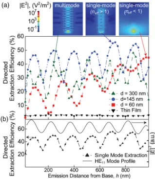
Fig. 1 (a) Schematic of simulation setup in x–z plane, with emission source [quantum well (QW)] at a distance h from the substrate. The nanowire cross-sections are assumed to be (b) an equi-lateral triangle of side-length d for m-directional nanowires, with two semi-polar f11 ¯22g facets and one polar c-plane (0002) facet, and (c) a regular hexagon of side-length aeqfor c-directional
nano-wires with six nonpolar m-plane f1 ¯100g facets. Black dots in (b) and (c) represent the center of the cross-section and gray dots represent the location of additional point sources used to simulate the full QW.
parallel to the plane of extraction;15 thus the highest extraction efficiency is expected for the m-directional axial heterostructure.
3 Directed Extraction Efficiency in Nanowire-Based LEDs
The extraction efficiency of thin films is generally limited by total internal reflection due to the large index of refraction contrast between GaN and air. Only light within an escape cone (22 deg for GaN) is extracted. In contrast, nanowires confine light into waveguide modes, guiding emis-sion toward extraction. In the regime in which the nanowire supports waveguide modes with effective indices (neff) greater than the superstrate refractive index, the electric-field intensity of
the light is primarily confined within the nanowire. If the cross-sectional area is too small, the nanowire will still guide the fundamental mode; however, most of the electric-field intensity of such a“leaky mode” will be outside of the nanowire and the extraction efficiency will depend heavily on its surroundings, typically other nanowires.
To estimate nanowire side-length regimes for which well-confined waveguiding is sustained, we calculated the dispersion relation for the first six modes in GaN nanowire waveguides [Fig. 3(a)]. The normalized propagation constant, ωd∕c, where ω is the angular frequency, is proportional to the ratio of nanowire side-length and wavelength, d∕λ, while the effective index, neff, is higher for more confined modes. At the wavelength of 405 nm, the
single-mode regime—where only the fundamental mode HE11 exists—is calculated to be sustained for d < 160 nm and aeq< 76 nm in the case of m- and c-directional nanowires, respectively,
which is in agreement with previously reported values.28,29 Each mode has a distinct cross-sectional electric-field intensity profile [Fig.3(b)]. The overall intensity varies along the length
Fig. 2 Schematic of expected relative emission orientation for III-nitride nanowire-based light-emitting diode designs: (a) m-directional axial, (b) c-directional radial, and (c) c-directional axial heterostructures.
Fig. 3 (a) Dispersion relation of the first six modes of nanowire waveguides plotted for both m-(solid lines) and c-directional (dashed lines) nanowires, also plotted against d (or aeq·
ffiffiffi 6 p
for hex-agonal cross-sections) at the emission wavelength of 405 nm. (b) The cross-sectional electric-field intensity profiles of the lower order modes. Note that the symmetry is broken due to the difference in cross-section along the x- and y-axes.
of the nanowire with the effective wavelength of the mode, but the relative intensities within the cross-section maintain the distinct modal profile. Note that the dispersion is remarkably similar for the m- and c-directional fundamental modes, especially in the single-mode regime, which indicates that for nanowires of equal cross-sectional area the modal properties should be similar. The cross-sectional intensity profiles of the fundamental mode are also both approximately radi-ally symmetric, indicating that coupling to the fundamental mode should have the same trend with respect to distance from the nanowire center, which is important when considering coupling changes throughout the cross-section.
Next, we focus on m-directional nanowires, for which the most coupling to modes is expected based on the polarization argument discussed above. We calculate the directed extrac-tion efficiency for m-direcextrac-tional nanowires in various waveguide regimes (leaky single-mode nanowires, with neff of the fundamental mode <1, well-confined single-mode nanowires
with neff of the fundamental mode >1, and multimode nanowires) and compare it with a
1-μm c-plane GaN thin-film on silicon as a function of the QW position [Fig. 4(a)]. Here, QWs were approximated as a single, centered point source to reduce the number of simulations necessary for this general comparison. For the thin film, the extraction efficiency is independent of QW position and limited to about 4% by total internal reflection. For nanowires, however, the extraction efficiency is generally higher and dependent on QW position and nanowire diameter. Extraction from a thin single-mode nanowire (d ¼ 60 nm, neff < 1) shows a maximum directed
extraction efficiency of 45% near the nanowire tip and a minimum of 1.2% near the substrate with oscillations approximately equivalent to the free-space wavelength, λ0¼ 405 nm. The steady increase in extraction as the QW is positioned closer to the nanowire tip is due to an increased emission from extraction cones on the nanowire side-facets as the source is moved toward the plane of extraction. The oscillations can be attributed to the fact that for leaky single-mode nanowires-extracted light mostly propagates outside the nanowire and inter-feres with itself after reflection from the surface of the silicon substrate. The oscillations in extraction efficiency from a thicker (d ¼ 145 nm, neff > 1) single-mode nanowire waveguide
between a maximum of 56% and a minimum of 21% (near the substrate) can be ascribed to the same effect, where the oscillations correspond to the effective wavelength of the mode,λ0∕neff.
Fig. 4 (a) Directed extraction efficiency as a function of the QW placement for leaky and well-confined single-mode and multimode m-directional nanowire waveguides compared with a thin film. (b) Comparison of well-confined single-mode nanowire waveguide extraction and electric-field intensity of the fundamental mode profile.
We further explore the origin of the oscillations in directed extraction efficiency by directly comparing it with the electric-field intensity profile of the standing wave excited by the funda-mental mode in a single-mode nanowire waveguide with neff > 1 [Fig.4(b)]. Since the directed
extraction efficiency is primarily due to extraction of the fundamental mode, the intensity profile and directed extraction efficiency follow the same oscillation pattern (coupling of the dipole emission is expected to be strongest at maxima in the electric-field intensity profile15). This
trend is obscured in c-directional nanowires due to the polarization anisotropy, which results in less coupling to the fundamental mode. When the nanowire side-length is increased even further such that multiple modes become active, much more complicated dependency on QW position is observed [Fig. 4(a)]. For example, for a nanowire with d ¼ 300 nm, up to six total modes exist within the nanowire, resulting in overall lower directed extraction due to lower overall coupling from a discrete source, with maximum and minimum extraction effi-ciencies of 48% and 13%, respectively.
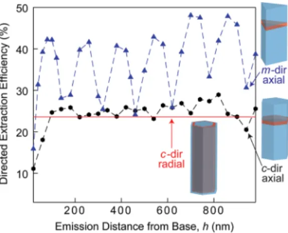
After considering different nanowire waveguide regimes, we next compare the overall-directed extraction efficiency of well-confined single-mode m- and c-directional axial and radial heterostructures (Fig. 5), with d ¼ 145 nm and aeq¼ 59 nm, respectively. Unless otherwise
noted, we focus on these well-confined single-mode nanowires for the remainder of this work. The c-directional radial heterostructure was found for a QW placed at 0.9 the distance from the center to the surface, where extraction has previously been reported to be optimal.15The m-directional axial heterostructure has strikingly larger extraction as compared with the c-direc-tional axial and radial heterostructures, but the placement of the QW is critical to optimize the extraction efficiency, as discussed above. In contrast, the c-directional axial heterostructure has much less variation, as most of the emission is oriented parallel to the plane of extraction. While this result indicates that m-directional axial heterostructures have an advantage in terms of directed light extraction, expected differences in the IQE must also be considered, which we discuss later in the text.
Our results demonstrate that regardless of their side-length, nanowires exhibit enhanced extraction efficiency over an unprocessed thin film. It should be noted, however, that extraction efficiencies from thin films can be greatly enhanced via surface roughening,35reflective back-side contacts,36photonic crystal patterning,37and flip-chip designs.38Extraction efficiencies of up to 80% have been reached in optimized devices.39 However, well-confined single-mode m-directional nanowires can achieve extraction efficiencies near 50% without any additional processing steps, simply by placing the QW at the proper position along the nanowire. We also note that nanowire arrays may be able to reach even higher extraction efficiencies, but the calculation of extraction efficiency here is meant as a starting point to compare m- and c-directional nanowires for LED applications.
Fig. 5 Simulated directed extraction efficiency as a function of the QW placement for m- and directional axial heterostructures, with the solid line indicating the extraction efficiency for a c-directional radial heterostructure with the QW placed at 0.9 the distance from the center to the surface.
4 Modeling Internal and External Quantum Efficiency
The A-B-C model is often used to model the IQE and compare relative recombination rates for LEDs. This simple model is intuitive and provides a physical insight into the dominant recombi-nation mechanisms in the device.40The current density, J, and the IQE are dependent on the carrier density, n, in the active region of the device (in this case the QW) as shown in Eqs. (1) and (2), respectively: J qw¼ An þ Bn 2þ Cn3; (1) IQE ¼ Bn A þ Bn þ Cn2; (2)
where q is the elementary charge, w is the active region width (approximated by the QW width), and the coefficients A, B, and C represent the relative rates of nonradiative, radiative, and Auger recombination, respectively. The model assumes that the electron and hole densities are of the same order in the active region at nonequilibrium, that there is no carrier leakage across the QW, and that A, B, and C are only weakly dependent on n.40This model has been fitted to
exper-imental results for a c-directional axial nanowire heterostructure,41resulting in room-temperature values of A ¼ 7 × 10⁸ s−1, B ¼ 3 × 10⁻¹⁰cm3s−1, and C ¼ 4.5 × 10⁻²⁹cm6s−1. Though this device is different from the simpler ones we are simulating, it is a useful starting point for com-parison, as the characteristics of a multi-QW system are often dominated by a single QW, typ-ically the one closest to the more resistive p-type layer.40
While the values for B and C depend primarily on the LED design [QW orientation, number of QWs, existence of electron blocking layers (EBLs)], the values for A are specific to size and geometry in nanowire-based LEDs; thus, we cannot simply use A from the experimental refer-ence.41Nonradiative recombination can occur due to trap states or nonradiative recombination centers such as dislocations or surface states. In nanowires, it is expected that nonradiative recombination is mostly governed by the surface recombination due to the high surface-to-vol-ume-ratio, and the fact that dislocations are not present.14For a typical thin-film GaN LED, the nonradiative recombination rate has been reported as Abulk¼ 5.4 × 10⁷ s−1, representing an
esti-mate for bulk nonradiative recombination rate in the regime of low threading dislocation den-sities.42 (In an ideal case with no dislocations and low surface recombination, A would be equivalent to such a bulk value.) We used this bulk value as a comparison against the values dominated by surface recombination, as expected in a nanowire-based device. For a c-directional axial heterostructure with nonpolar facets, based on the values measured experimentally,23,41,43 assuming a surface depletion region44,45based on a doping density of 1018 cm−3and extracting
to the geometries considered here, we obtain a value of Ac-directional¼ 2.9 × 10⁸ s−1. Similarly,
for m-directional nanowires with higher surface recombination at the polar c-plane facets,23we estimate a higher Am-directional¼ 5.5 × 10⁸ s−1. Using the experimental values for B and C cited
above and varying A from the bulk value to the calculated values for c- and m-directional axial heterostructures (as summarized in Table1), the general IQE is found to decrease from the ideal bulk-like case to the c-directional axial heterostructure, with the m-directional axial heterostruc-ture displaying the lowest IQE [Fig. 6(a)].
The above consideration only takes into account the trend with surface recombination and does not account for changes in radiative recombination between m- and c-directional axial heterostructures, which we discuss next. The coefficient B represents the amount of radiative recombination, thus for high IQE it is desirable for B to be large. Since the radiative recombi-nation probability is expressed by Fermi’s golden rule, which is proportional to the matrix element of wave function overlap, jMj2, B is directly proportional to jMj2. To estimate B
for different nanowire configurations, the QCSE must be taken into account. Due to the elec-tric-field induced by the polarity in the c-direction of GaN and the piezoelectric effect shifting apart the electron and hole wave functions,22the QCSE is significant for c-plane QWs resulting in a lowerjMj2for c-plane QWs than m-plane QWs, where the effect is absent. This difference
results in a higher spontaneous emission rate for m-plane QWs, and thus a higher B. In sim-ulating the QCSE in InGaN QWs using self-consistent and flat-band models, it has been reported
that for m-plane QWs jMj2 is enhanced by up to a factor of eight and at least a factor of two
compared with c-plane QWs, respectively.22These factors are thus multiplied by the baseline B for c-plane QWs (3 × 10⁻¹⁰ cm3s−1) to arrive at an estimate of B for both the self-consistent
(2.4 × 10⁻⁹ cm3s−1) and flat-band (6 × 10⁻¹⁰cm3s−1) models. The resulting IQE for this range
of B values is shown in Fig.6(b), for both nanowire-like and bulk-like nonradiative recombi-nation. The minimum IQE curves in each case represent a c-plane QW and the intermediate (dashed) and maximum curves represent the flat-band model (low) and self-consistent model (high) estimates for an m-plane QW, respectively (see Table 1). Experimental results have shown that thin-film devices grown in the m-direction have IQEs about a factor of two higher than the devices grown in the c-direction,46which supports using the flat-band model estimate in whichjMj2is also a factor of two higher in m-plane QWs than in c-plane QWs. Thus, a value of
B ¼ 6 × 10⁻¹⁰cm3s−1 is used henceforth for m-directional axial heterostructures.
Effects of the QCSE and surface recombination discussed above were then combined [Fig. 6(c)] to calculate a range of IQEs for both c- and m-directional axial heterostructures (see Table1). In general, it is likely that c-directional axial heterostructures will have a higher IQE at lower current densities due to lower surface recombination compared with m-directional axial heterostructures. As the current density increases, m-directional axial heterostructures will likely have higher IQEs due to enhanced radiative recombination as compared with c-directional
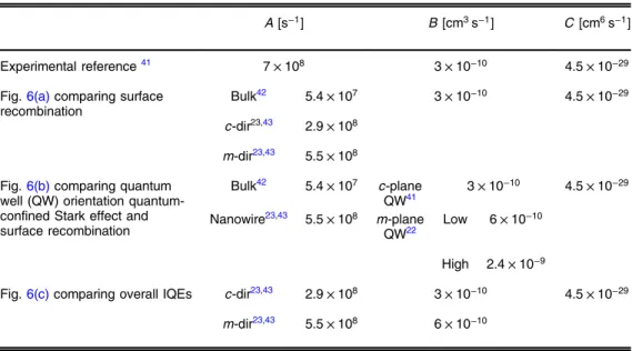
Table 1 Coefficients of the A-B-C model used in comparing internal quantum efficiency (IQE).
A [s−1] B [cm3s−1] C [cm6s−1]
Experimental reference41 7 × 10⁸ 3 × 10⁻¹⁰ 4.5 × 10⁻²⁹
Fig.6(a)comparing surface recombination
Bulk42 5.4 × 10⁷ 3 × 10⁻¹⁰ 4.5 × 10⁻²⁹
c-dir23,43 2.9 × 10⁸
m-dir23,43 5.5 × 10⁸ Fig.6(b)comparing quantum
well (QW) orientation quantum-confined Stark effect and surface recombination Bulk42 5.4 × 10⁷ c-plane QW41 3 × 10 −10 4.5 × 10⁻²⁹ Nanowire23,43 5.5 × 10⁸ m-plane QW22 Low 6 × 10⁻¹⁰ High 2.4 × 10⁻⁹
Fig.6(c)comparing overall IQEs c-dir23,43 2.9 × 10⁸ 3 × 10⁻¹⁰ 4.5 × 10⁻²⁹
m-dir23,43 5.5 × 10⁸ 6 × 10⁻¹⁰
Fig. 6 (a) The effect of increasing surface recombination on expected internal quantum efficiency (IQE) assuming constant B and C, and varying A. (b) The range of expected IQEs for bulk and nanowire cases, where minimal IQE represents radiative recombination from a c-plane QW and the dashed and maximum IQE curves represent low and high-end estimates for B from an m-plane QW. (c) The range of expected IQEs from m- and c-directional axial heterostructures using the low-end estimate of B for the m-plane QW with the range minimum and maximum determined by extent of surface recombination. See Table1.
axial heterostructures. These results do not include potential effects of the crystallographic ori-entation on electron overflow through the QW. It has been shown that nonpolar QW oriori-entations decrease electron overflow relative to polar QW orientations without an EBL; however, the inclu-sion of an EBL results in similar output powers.47Note that the c-directional radial heterostruc-ture has been excluded from this analysis, as a direct comparison to experimental results could not be made.
Finally, we estimate the EQE range (Fig. 7) by multiplying the minimum and maximum directed extraction efficiency dependent on QW placement (as determined by FDTD, Fig.5) by the expected IQE [Fig.6(c)]. It is assumed that nanowires are not surface-passivated, effec-tively giving a conservative estimate for the EQE. For the optimal QW placement, m-directional axial heterostructures generally have a higher EQE, mostly due to the differences in extraction. For the least optimal QW placement, c-directional axial heterostructures have a higher EQE for very small current densities, but the m-directional axial heterostructures still outperform the c-directional axial heterostructures at higher current densities, despite a higher amount of surface recombination expected for the m-directional nanowires.
Several assumptions were made to arrive at the EQE results in Fig.7, and here we discuss deviations from these assumptions. First, it is assumed that the cross-sections of the nanowires are highly symmetric. In reality, these cross-sections do not generally have perfectly sharp cor-ners;19changes in symmetry will further lift the degeneracy of the modes and slightly change
their effective indices, which should not play a significant role on the results besides on the optimal QW placement. Nanowire devices are often encapsulated by a superstrate other than air, such as benzocyclobutane,48which would raise the index of refraction of the superstrate and reduce the effective indices of the waveguide modes, shifting dispersion, and the optimal QW placement. Similarly, for different QW compositions and sizes, the emission wavelength would be different, resulting in shifting to a different point in the dispersion, and thus a different opti-mal QW placement. At longer wavelengths the modes will be less confined and thus the directed efficiency would be decreased. Whereas the nanowire diameter could then be increased to obtain a well-confined single mode atλ0 ¼ 550 nm (green), this would move the regime at λ0¼ 405 nm (blue) to multimode, making designs for multiple QW challenging to optimize.
For multiple QWs of different emission wavelengths, the trade-off between optimal QW place-ment and electrical injection would also need to be considered. Furthermore, the designs ana-lyzed here take advantage of a reflective silicon substrate. Alternative substrates such as sapphire are transparent, which would necessitate the development of different designs, as most of the emission reaching the substrate in this design would be lost for transparent sub-strates. Such designs would likely mimic thin-film devices, which often emit through the sap-phire and are designed with a silver-based contact to reflect emitted light back toward the sapphire and tune emission.39,49
This work simulated only individual nanowires, thus motivating the use of directed extraction rather than overall extraction from the nanowire (i.e., including free space emission from the nanowire sidewalls). We note that in many cases, much of the light is in fact not guided by
Fig. 7 Estimated external quantum efficiency ranges for m- and c-directional axial heterostruc-tures obtained by combining IQE modeling and directed extraction efficiency simulations from finite-difference time domain.
the nanowire (i.e., undirected) and thus not considered in our definition of directed extraction efficiency, even though the light does escape the nanowire, it is not directed substantially away from the substrate toward an observer. For cases where most of the light is confined within the nanowire, array effects should be minimal with nanowires spaced adequately apart, and thus the overall efficiency would be close to the directed efficiency in such cases. It should be noted that thinner nanowires will have large portions of light intensity outside of the nanowire, for which the density of nanowires on the substrate should more strongly affect the extraction.50
Furthermore, it may be possible to form a photonic crystal with an array of nanowires to prevent propagation along the plane extraction and suppress emission not oriented toward extraction.51 While future work will consider nanowire arrays and the potential to further enhance light extrac-tion by taking advantage of undirected extracextrac-tion, this work demonstrates that m-direcextrac-tional axial heterostructures are the most efficient for guided extraction, and thus likely to be the most efficient overall design.
Besides considerations that affect optimal QW placement and the role of nanowire density, the material quality and processing can play important roles. The effect of the surface depletion region, while considered in the IQE modeling, was not integrated into the FDTD simulations (as calculated widths were small, only on the order of 10 nm); however, large surface depletion regions could actually enhance the extraction efficiency, by limiting emission to the center of the nanowire, where extraction efficiency is expected to be highest. Though nanowires grown by the self-induced method in plasma-assisted molecular beam epitaxy often display flat surface fac-ets,11seed-mediated nanowires would normally have a metallic seed-particle at the nanowire tip, which may quench emission or scatter the waveguide modes, effectively reducing extraction efficiency. It is possible to chemically etch such seed-particles.52Finally, nanowire sidewall
sur-face roughness would induce losses and decrease the overall extraction efficiency.
5 Conclusions
In this work, we compared designs of III-nitride nanowire-based LEDs using a combination of FDTD photonic simulations and the A-B-C model for IQE. We showed that individual well-confined single-mode nanowires have the highest directed extraction efficiency and that the variation of directed extraction efficiency as a function of QW placement could be directly related to the expected coupling to the fundamental mode in this case. Furthermore, due to the large polarization anisotropy expected in InGaN QWs, m-directional axial heterostructures were found to have the highest directed extraction efficiencies as compared with c-directional axial and radial heterostructures in the well-confined single-mode regime, as more of the emis-sion can be coupled to the fundamental mode. The placement of the QW was also found to be more important in the m-directional axial heterostructure due to the strong coupling to the fun-damental mode, demonstrating oscillation between a maximum directed extraction efficiency of 49% and a minimum of 24%. The A-B-C model was used to discuss the effects of nonradiative and radiative recombination within m- and c-directional axial heterostructures. The m-direc-tional nanowires are expected to have a slightly higher nonradiative recombination rate, due to the polar c-plane side-facet; however, the m-directional axial heterostructure is also expected to have a higher radiative recombination rate due to the QCSE reducing the radiative recombi-nation rate in c-directional axial heterostructures. Finally, by combining these results, the expected EQE ranges were estimated for both m- and c-directional axial heterostructures, dem-onstrating that the m-directional axial heterostructures generally have a higher EQE, due pri-marily to the large role that polarization anisotropy plays in the directed extraction efficiency and the enhanced radiative recombination rate by avoiding the QCSE.
Though this work only considered blue-emitters, the same approach used here can be applied to any emission wavelength to find the optimal QW placement. By looking at the optimal place-ment for green and red wavelengths, it would be possible to design a white LED with QWs emitting at each wavelength positioned optimally all within a single nanowire. High-efficiency LEDs using m-directional axial heterostructures operated at high current densities could be fur-ther improved by coating the nanowires with a high band-gap shell, such as AlxGa1−xN, to
periodically in a photonic crystal arrangement, it may be possible to boost the extraction effi-ciency by suppressing propagation parallel to the plane of extraction. This work will help to guide the design of such future III-nitride nanowire-based LEDs to reach higher efficiencies, which will help to progress the solid state lighting revolution.
Acknowledgments
This work was supported by the Center for Excitonics, an Energy Frontier Research Center funded by the U.S. Department of Energy, Office of Science, Office of Basic Energy Sciences, under Award Number DE-SC0001088.
References
1. J. J. Conti et al., Annual Energy Outlook 2012, US Department of Energy’s Energy Information Agency, Washington, DC (2012).
2. C. J. Humphreys, “Solid-state lighting,” MRS Bull. 33(4), 459–470 (2008), http://dx.doi .org/10.1557/mrs2008.91.
3. K. Kohler et al., “Control of the Mg doping profile in III-N light-emitting diodes and its effect on the electroluminescence efficiency,” J. Appl. Phys. 97(10), 104914 (2005),
http://dx.doi.org/10.1063/1.1901836.
4. Z. H. Wu et al.,“Structural and optical properties of nonpolar GaN thin films,” Appl. Phys. Lett. 92(17), 171904 (2008),http://dx.doi.org/10.1063/1.2918834.
5. R. F. Davis, “III-V nitrides for electronic and optoelectronic applications,” Proc. IEEE 79(5), 702–712 (1991),http://dx.doi.org/10.1109/5.90133.
6. S. Arafin, X. Liu, and Z. Mi, “Review of recent progress of III-nitride nanowire lasers,” J. Nanophotonics 7(1), 074599 (2013),http://dx.doi.org/10.1117/1.JNP.7.074599. 7. S. Chowdhury et al.,“Current status and scope of gallium nitride-based vertical transistors
for high-power electronics application,” Semicond. Sci. Technol. 28(7), 074014 (2013),
http://dx.doi.org/10.1088/0268-1242/28/7/074014.
8. A. Dadgar et al.,“Improving GaN-on-silicon properties for GaN device epitaxy,” Phys. Stat. Sol. C 8(5), 1503–1508 (2011), http://dx.doi.org/10.1002/pssc.201001137.
9. Y. B. Tang et al.,“Vertically aligned p-type single-crystalline GaN nanorod arrays on n-type Si for heterojunction photovoltaic cells,” Nano Lett. 8(12), 4191–4195 (2008),http://dx.doi .org/10.1021/nl801728d.
10. W. Guo et al.,“Catalyst-free InGaN/GaN nanowire light emitting diodes grown on (001) silicon by molecular beam epitaxy,” Nano Lett. 10(9), 3355–3359 (2010),http://dx.doi.org/ 10.1021/nl101027x.
11. H. P. T. Nguyen et al.,“Full-color InGaN/GaN dot-in-a-wire light emitting diodes on sil-icon,” Nanotechnology 22(44), 445202 (2011),http://dx.doi.org/10.1088/0957-4484/22/44/ 445202.
12. K. Cheng et al., “High quality GaN grown on silicon(111) using a SixNy interlayer by metal-organic vapor phase epitaxy,” Appl. Phys. Lett. 92(19), 192111 (2008), http://dx .doi.org/10.1063/1.2928224.
13. N. Baron et al., “The critical role of growth temperature on the structural and electrical properties of AlGaN/GaN high electron mobility transistor heterostructures grown on Si (111),” J. Appl. Phys. 105(3), 033701 (2009),http://dx.doi.org/10.1063/1.3063698. 14. H. P. T. Nguyen et al.,“Temperature-dependent nonradiative recombination processes in
GaN-based nanowire white-light-emitting diodes on silicon,” Nanotechnology 23(19), 194012 (2012),http://dx.doi.org/10.1088/0957-4484/23/19/194012.
15. A.-L. Henneghien et al.,“Simulation of waveguiding and emitting properties of semicon-ductor nanowires with hexagonal or circular sections,” J. Opt. Soc. Am. B 26(12), 2396– 2403 (2009),http://dx.doi.org/10.1364/JOSAB.26.002396.
16. Q. Li and G. T. Wang,“Improvement in aligned GaN nanowire growth using submonolayer Ni catalyst films,” Appl. Phys. Lett. 93(4), 043119 (2008), http://dx.doi.org/10.1063/1 .2965798.
17. X. Zhou et al.,“Using seed particle composition to control structural and optical properties of GaN nanowires,” Nanotechnology 23(28), 285603 (2012), http://dx.doi.org/10.1088/ 0957-4484/23/28/285603.
18. L. Largeau et al.,“Facet and in-plane crystallographic orientations of GaN nanowires grown on Si(111),” Nanotechnology 19(15), 155704 (2008),http://dx.doi.org/10.1088/0957-4484/ 19/15/155704.
19. S. K. Lim et al., “Controlled modulation of diameter and composition along individual III-V nitride nanowires,” Nano Lett. 13(2), 331–336 (2013), http://dx.doi.org/10.1021/ nl300121p.
20. N. F. Gardner et al.,“Polarization anisotropy in the electroluminescence of m-plane InGaN– GaN multiple-quantum-well light-emitting diodes,” Appl. Phys. Lett. 86(11), 111101 (2005),http://dx.doi.org/10.1063/1.1875765.
21. T. Kolbe et al., “Optical polarization characteristics of ultraviolet (In)(Al)GaN multiple quantum well light emitting diodes,” Appl. Phys. Lett. 97(17), 171105 (2010),http://dx .doi.org/10.1063/1.3506585.
22. S.-H. Park,“Crystal orientation effects on electronic properties of wurtzite InGaN/GaN quantum wells,” J. Appl. Phys. 91(12), 9904 (2002), http://dx.doi.org/10.1063/1 .1480465.
23. K. Jarašinas et al., “Recombination and diffusion processes in polar and nonpolar bulk GaN investigated by time-resolved photoluminescence and nonlinear optical techniques,” Proc. SPIE 8262, 82620G (2012),http://dx.doi.org/10.1117/12.906303.
24. N. Mochida et al.“Crystal orientation dependence of p-type contact resistance of GaN,” J. Crys. Gro. 189–190, 716–719 (1998), http://dx.doi.org/10.1016/S0022-0248(98) 00269-3.
25. T.-W. Yeh et al.,“InGaN/GaN multiple quantum wells grown on nonpolar facets of vertical GaN nanorod arrays,” Nano Lett. 12(6), 3257–3262 (2012), http://dx.doi.org/10.1021/ nl301307a.
26. F. Qian et al., “Core/multishell nanowire heterostructures as multicolor, high-efficiency light-emitting diodes,” Nano Lett. 5(11), 2287–2291 (2005), http://dx.doi.org/10.1021/ nl051689e.
27. F. Qian et al.,“Gallium nitride-based nanowire radial heterostructures for nanophotonics,” Nano Lett. 4(10), 1975–1979 (2004),http://dx.doi.org/10.1021/nl0487774.
28. A. V. Maslov, M. I. Bakunov, and C. Z. Ning,“Distribution of optical emission between guided modes and free space in a semiconductor nanowire,” J. Appl. Phys. 99(2), 024314 (2006),http://dx.doi.org/10.1063/1.2164538.
29. M.-K. Seo et al.,“Modal characteristics in single NW cavity with triangular cross-section,” Nano Lett. 8(12), 4534–4538 (2008),http://dx.doi.org/10.1021/nl8027125.
30. B. Witzigmann et al.,“Optical properties of individual GaN nanorods for light emitting diodes: influence of geometry, materials, and facets,” Proc. SPIE 7933, 793314 (2011),
http://dx.doi.org/10.1117/12.874984.
31. C. Kölper et al.,“Core-shell InGaN nanorod light emitting diodes: electronic and optical device properties,” Phys. Stat. Sol. A 209(11), 2304–2312 (2012),http://dx.doi.org/10.1002/ pssa.v209.11.
32. A. Chutinan et al.,“Theoretical analysis on light-extraction efficiency of organic light-emit-ting diodes using FDTD and mode-expansion methods,” Org. Elec. 6(1), 3–9 (2005),http:// dx.doi.org/10.1016/j.orgel.2004.12.001.
33. J. Chesin, X. Zhou, and S. Gradečak, “Light extraction in individual GaN nanowires on Si for LEDs,” Proc. SPIE 8467, 846703 (2012),http://dx.doi.org/10.1117/12.970456. 34. S. Ghosh et al., “Polarization-dependent spectroscopic study of M-plane GaN on
γ-LiAlO2,” Appl. Phys. Lett. 80(3), 413–415 (2002),http://dx.doi.org/10.1063/1.1434306.
35. T. Fujii et al.,“Increase in the extraction efficiency of GaN-based light-emitting diodes via surface roughening,” Appl. Phys. Lett. 84(6), 855–857 (2004),http://dx.doi.org/10.1063/1 .1645992.
36. T. Jeong et al.,“Enhanced light output power of GaN-based vertical light-emitting diodes by using highly reflective ITO-Ag-Pt reflectors,” IEEE Photonics Tech. Lett. 20(23), 1932– 1935 (2008),http://dx.doi.org/10.1109/LPT.2008.2005421.
37. F. Rahman and A. Z. Khokhar,“Enhanced photoluminescence from photonic crystal-coated GaN LED wafers,” Appl. Phys. B 103(3), 623–628 (2011), http://dx.doi.org/10.1007/ s00340-011-4545-9.
38. O. B. Shchekin et al.,“High performance thin-film flip-chip InGaN-GaN light-emitting diodes,” Appl. Phys. Lett. 89(7), 071109 (2006), http://dx.doi.org/10.1063/1.2337007. 39. M. R. Krames et al.,“Status and future of high-power light-emitting diodes for solid-state
lighting,” J. Disp. Tech. 3(2), 160–175 (2007),http://dx.doi.org/10.1109/JDT.2007.895339. 40. K. A. Bulashevich et al.,“Simulation of light-emitting diodes for new physics understand-ing and device design,” Proc. SPIE 8278, 827819 (2012), http://dx.doi.org/10.1117/12 .912305.
41. H. P. T. Nguyen et al.,“Controlling electron overflow in phosphor-free InGaN/GaN nano-wire white light-emitting diodes,” Nano Lett. 12(3), 1317–1323 (2012),http://dx.doi.org/10 .1021/nl203860b.
42. Y. C. Shen et al.,“Auger recombination in InGaN measured by photoluminescence,” Appl. Phys. Lett. 91(14), 141101 (2007),http://dx.doi.org/10.1063/1.2785135.
43. H.-Y. Chen et al.,“Size-dependent persistent photocurrent and surface band bending in m-axial GaN nanowires,” Phys. Rev. B 84(20), 205443 (2011), http://dx.doi.org/10 .1103/PhysRevB.84.205443.
44. A. Gorgis et al., “Time-resolved photoluminescence spectroscopy of individual GaN nanowires,” Phys. Rev. B 86(4), 041302 (2012), http://dx.doi.org/10.1103/PhysRevB.86 .041302.
45. B. S. Simpkins et al., “Surface depletion effects in semiconducting nanowires,” J. Appl. Phys. 103(10), 104313 (2008),http://dx.doi.org/10.1063/1.2932072.
46. X. Ni et al.,“Internal quantum efficiency of c-plane InGaN and m-plane InGaN on Si and GaN,” Appl. Phys. Lett. 95(10), 101106 (2009),http://dx.doi.org/10.1063/1.3224192. 47. J.-I. Chyi et al.,“Nonpolar and semipolar GaN, optical gain and efficiency,” Proc. SPIE
8625, 862511 (2013), http://dx.doi.org/10.1117/12.2025079.
48. M. Lee et al., Packaging and interconnect technologies for the development of GaN nano-wire-based light emitting diodes, IEEE, San Diego, CA (2009).
49. Y.-K. Su et al.,“Enhancement in light extraction of GaN-based light-emitting diodes with high reflectivity electrodes,” IEEE Photonics Tech. Lett. 23(23), 1793–1795 (2011). 50. A.-L. Henneghien et al.,“Optical anisotropy and light extraction efficiency of MBE grown
GaN nanowires epilayers,” Opt. Express 19(2), 527–539 (2011),http://dx.doi.org/10.1364/ OE.19.000527.
51. S. L. Diedenhofen et al.,“Controlling the directional emission of light by periodic arrays of heterostructured semiconductor nanowires,” ACS Nano 5(7), 5830–5837 (2011),http://dx .doi.org/10.1021/nn201557h.
52. M. J. Tambe, S. Ren, and S. Gradečak, “Effects of gold diffusion on n-type doping of GaAs nanowires,” Nano Lett. 10(11), 4584–4589 (2010),http://dx.doi.org/10.1021/nl102594e. Jordan Chesinis a doctoral candidate at the Massachusetts Institute of Technology in materials science and engineering. He received his BS in materials science and engineering from Brown University in 2009. His current research interests include the growth, characterization, and device fabrication of III-nitride and ZnO nanowires on silicon substrates for optoelectronics applications, particularly for LEDs.
Silvija Gradečak is an associate professor of materials science and engineering at the Massachusetts Institute of Technology. She received her BS and PhD in physics from the University of Zagreb in 1999 and the Swiss Federal Institute of Technology in 2003, respec-tively. Her research group works on the synthesis, characterization, and application of nanoma-terials for LEDs and solar cells and uses advanced electron microscopy techniques to study the interplay of materials processing, properties and performance.