HAL Id: hal-02446529
https://hal.archives-ouvertes.fr/hal-02446529
Submitted on 20 Jan 2020
HAL is a multi-disciplinary open access
archive for the deposit and dissemination of
sci-entific research documents, whether they are
pub-lished or not. The documents may come from
teaching and research institutions in France or
abroad, or from public or private research centers.
L’archive ouverte pluridisciplinaire HAL, est
destinée au dépôt et à la diffusion de documents
scientifiques de niveau recherche, publiés ou non,
émanant des établissements d’enseignement et de
recherche français ou étrangers, des laboratoires
publics ou privés.
Network Function Mapping: from 3G Entities to 5G
Service-Based Functions Decomposition
Wesley da Silva Coelho, Amal Benhamiche, Nancy Perrot, Stefano Secci
To cite this version:
Wesley da Silva Coelho, Amal Benhamiche, Nancy Perrot, Stefano Secci. Network Function
Map-ping: from 3G Entities to 5G Service-Based Functions Decomposition. IEEE Communications
Stan-dards Magazine, Institute of Electrical and Electronics Engineers, 2020, 4 (3),
�10.1109/MCOM-STD.001.1900040�. �hal-02446529�
Network Function Mapping: from 3G Entities to 5G
Service-Based Functions Decomposition
Wesley da Silva Coelho
§†, Amal Benhamiche
§, Nancy Perrot
§, Stefano Secci
†A
BSTRACTThe Third Generation Partnership Project (3GPP) was established to bring together several standards organization to address the needs related to the specification of mobile broadband. Originally targeting the evolution from 2G to 3G, 3GPP continues at the forefront of the standardization effort leading to 5G and beyond. Given the growing diversity of services and the explosion of mobile users year by year, evolving architectures have then been successively proposed by the group in order to expand the limits of legacies systems. We overview this evolution, summarizing the transformation of core systems and their related decomposition, aggregation, and mapping operations from 3G to 5G systems. We also present an in-depth description of 5G Core based on recent technical documents delivered by 3GPP. We end with the identification of potential operational and technical challenges in 5G systems.
I
NTRODUCTIONThird Generation Partnership Project (3GPP) emerged from the need of technically specifying the third generation (3G) mobile network. Such specifications were structured in docu-ments called Releases: the first one was issued in 1999, called Release 99 [1]. At that time, 3GPP’s work was based on Global System for Mobile communication networks, also called 2G systems. The Core Network is responsible for all control and central processing for the 3G system, being an evolution of the legacy Network Switching Subsystem. For the conventional Circuit Switched domain, 3G core network was conceived with Mobile Switching Center (MSC) and MSC Gateway (GMSC) entities, responsible for carrying calls from network users and interfacing with external circuit-based networks, respectively. 3G mobile technology supports a wide variety of services, ranging from multimedia applications available on the Internet. For this purpose, 3G core is also conceived with a Packet Switched domain to carry users’ data. As described by [2], this domain includes General Packet Radio Services Support Node (SGSN) and Gateway General Packet Radio Services Support Node (GGSN). While SGSN is the entity responsible for mobility, session management, and billing, GGSN can be seen as the main entity of the 3G core. In this architecture, GGSN is responsible for ensuring and managing the connection with ex-ternal packet switched networks, (e.g., Internet). Furthermore, Equipment Identity Register (EIR), Home Location Register
§Orange Labs, Chˆatillon, France.
†Conservatoire National des Arts et M´etiers, Paris, France.
(HLR), and Authentication Center (AuC) are the entities shared by both Circuit and Packet domains, and contain all administrative information of each subscribed User Equipment (UE). These entities are also responsible for connection rules and information and data protection.
C
OREN
ETWORKE
VOLUTION FROM3GTO4GTo better deal with the immense popularization of the Internet on mobile phones and to support a greater number of customers and volume of data, Release 8 [3] was delivered by 3GPP in 2009. Release 8 was the first document presenting standards for Long-Term Evolution (LTE) mobile system, so-called 4G. It is important to note that 3GPP did not change its name when moving to 4G (and beyond) technology specification.
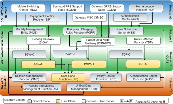
Release 8 presents standards for the Packet Switch system, called Evolved Packet Core (EPC). Within this new architec-ture, all services (e.g. voice, SMS, and data) are driven by the Internet Protocol (IP), which implies the disappearance of Circuit Switched domain from legacy Core Network. As de-picted in Fig. 1, MSC and EIR’s functionalities were combined into Mobility Management Entity (MME), the main control-ling entity in EPC. MME is responsible for authentication, roaming, and session management on the broadband network. It interfaces with two other entities, named Home Subscriber Server (HSS) and Serving Gateway (S-GW). The former is the database where all network user information is found and can be considered as an aggregation and evolution of HLR and AuC from 3G system. S-GW, in turn, has some functionalities from the legacy SGSN 3G core entity. It acts as mobility anchor during handovers and is responsible for routing users’ data packets. In that way, each user that accesses the EPC is associated with a single SGW, which interfaces with Packet Data Network Gateway (PDN-GW). This last entity is the essential interconnection point between EPC and external IP-based networks. It is also responsible for packet filtering, legal interception, and IP address allocation. Hence, PDN-GW has functionalities from GMSC and GGSN, combined. Finally, we find the Policy and Charging Rules Function (PCRF) within the EPC system. It is part of a functional framework called Policy and Charging Control (PCC), which is used to control the bearer services offered by the LTE network as well as to control the charging mechanisms. PCRF is a software component and is responsible for providing access rules and policies for core network gateways.
Fig. 1: 3GPP Network Core function evolution: from 3G to 5G.
SPLITTING4G CORE WITHCUPS
In order to offer a higher degree of modularity and scal-ability for core entities, 3GPP proposes a new architecture called CUPS: it stands for Control and User Plane Separation and offers a complete split between Control Plane (CP) and User Plane (UP). In this new EPC system, introduced in Release 14 [4], a more effective approach to support increasing and dynamic traffic is provided. With CUPS, UP and CP scaling can be made independently. For this purpose, S-GW becomes Serving Gateway Control Plane function (SGW-C) and Serving Gateway User Plane function (SGW-U). Equally, PDN-GW is split into PDN Gateway Control plane function (PGW-C) and PDN Gateway User Plane function (PGW-U). While SGW-C and PGW-C are responsible for controlling the processing of data that transverse User Plane functions, SGW-U and PGW-U implement specific features for a certain group of users, such as low latency or high bandwidth, to ensure Quality of Service (QoS). 3GPP has also proposed to split Traffic Detection Function (TDF) into CP and UP entities. TDF is part of PCC block [5] and is responsible for improving operator’s charging functions. With CUPS, TDF becomes TDF User Plane (TDF-U) and TDF Control Plane (TDF-C) functions.
FROM4GTO5G
The 5G architecture enhanced by Network Function Vir-tualization (NFV), Software Defined Networking (SDN), and Network Slicing provides an even more flexible environment supporting end-to-end customizable virtual networks. With dedicated resources to ensure specific QoS for a wide variety of services, all entities in 5G might be entirely or partially virtualized. 3GPP proposes 5G Core (5GC), another change in the mobile core network. Hence, 5GC presents the evolution
of the legacy entities found in 4G and additionally introduces optional Network Functions that might be necessary to con-trol and operate each slice. In the resulting new virtualized architecture, what were called entities in 3G and 4G are now called Network Functions in 5G.
As depicted in Fig. 1, MME functionalities are split into three new functions: Access and Mobility Management Function (AMF), Session Management Function (SMF) and Unified Data Management (UDM). AMF is responsible for registration, connection and reachability management, access authentication, and access authorization. UDM further shares responsibilities found in legacy HSS with the new Authentica-tion Server FuncAuthentica-tion (AUSF). SMF, in turn, is responsible for session management and takes all functionalities from PGW-C and SGW-PGW-C. Additionally, SMF will directly interface with 5G User Plane, which is represented by User Plane Function (UPF). In this context, UPF might apply all functionalities found in PGW-U, SGW-U and TDF-U, combined. Moreover, policies and charging rules, which were in 4G PCRF entity, are provided by the Policy Control Function (PCF), which interfaces with Application Function (AF); AF is meant to act like the logical 4G AF integrated into PCC framework [5], offering dynamic traffic information and applications based on user behaviors.
In this evolving context, we can identify a primary set of functions that need to be present to deploy a core slice. In that way, this slice must contain at least the basic functions connected to control and user planes: AMF, SMF, PCF, AUSF, UDM and UPF. Additionally, to better control and operate each slice in future 5G networks with specific requirements and technical constraints, several new functions are proposed by 3GPP [6]–[8]. Following, we present the main functionalities of these new functions:
• Network Exposure Function (NEF)- event and capability safe exposure to functions and third party networks.
• Non-3GPP Inter Working Function (N3IWF)- IP Security tunnel support in cases of untrusted non-3GPP accesses.
• Network Slice Selection Function (NSSF)- slice selection
for serving users.
• Unstructured Data Storage Function (UDSF)- informa-tion retrieval and storage as unstructured data.
• 5G-EIR - Permanent Equipment Identifier status check-ing.
• Network Data Analytics Function (NWDAF) - slice load level information.
• Charging Function (CHF) - online and offline charging
• Network Repository Function (NRF) - provides NF in-stances information such as function type, function ID, and Network Slice related Identifier(s).
• Unified Data Repository (UDR)- subscription and policy structured data retrieval and storage.
• SMS Function (SMSF)- SMS management and delivery
over Non-Access-Stratum.
• Location Management Function (LMF) - measures user, downlink and uplink location.
• Security Edge Protection Proxy (SEPP)- non-transparent proxy responsible for filtering and policing between Pub-lic Land Mobile Networks’ control planes.
• Binding Support Function (BSF) - supports binding in-formation updates by NF service consumers.
Figure 1 summarizes the aforementioned core network evolution, from 3G to 5G. For an in-depth functionality description of each 5G function, one may refer to [6]–[8].
5G C
ORES
PECIFICITIESTo better support network slicing, 3GPP has proposed more flexible, customized service-based network functions for 5G systems. With this new architecture, functions make use of a complete integrated interface that allows them to expose their capability to other authorized NFs without precluding the use of intermediate functions. This implies that all Control Plane functions have potential to directly communicate with each other by request/response and subscribe/notify application-level signaling. For this propose, each CP function is conceived with a set of NF services to be consumed by other functions. The interactions between CP functions are depicted in Fig. 2. In this example, A is a NF service consumer from B’s point of view, which is, in turn, a NF service producer from A’s perspective. Note that the same function may be service consumer and service producer at the same time, as illustrated by B. One function might consume services from different NF service producers and a function might also offer services for different NF service consumers. It is also important to notice that a NF service can provide and consume services to and from other NF services within the same function.
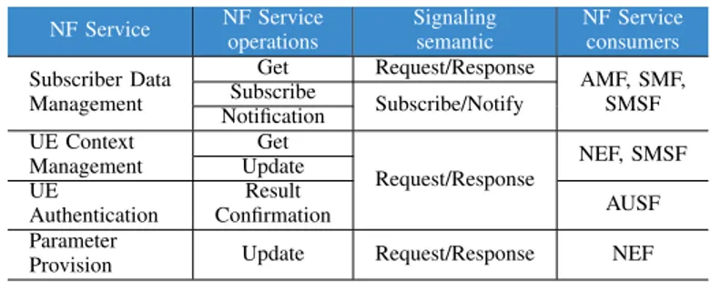
Fig. 2: Service-based interactions between network functions. 3GPP has also been providing some technical reports with a non exhaustive list of possible interactions between different functions and NF services [6], [9], [10]. Some of those iterations are exemplified on Table I, where UDM is taken as example with its non-exhaustive list of NF services [10]. Note that UDM is able to offer a same service to different NF service consumers. In this example, UDM can subscribe data from AMF, SMF and SMSF. It is also important to notice that a same service might make different operations (e.g. get, subscribe, update, result confirmation) and they are made by request/response and subscribe/notify queries.
TABLE I: Example of a NF service decomposition: UDM as NF service producer
NF Service NF Serviceoperations Signalingsemantic NF Serviceconsumers
Get Request/Response Subscribe Subscriber Data Management Notification Subscribe/Notify AMF, SMF, SMSF Get UE Context
Management Update NEF, SMSF UE Authentication Result Confirmation Request/Response AUSF Parameter
Provision Update Request/Response NEF
CUSTOMIZEDSERVICE-BASEDNETWORKFUNCTIONS
Legacy mobile networks lack the ability to provide a specific set of functionalities for each service proposed by operators, each one with a very specific technical requirement. 5G systems, leveraging NFV and SDN to support flexible data and service connectivity with an efficient deployment of customized slices, can offer a minimal and adapted set of core NFs for each case: each function can be programmed to contain only the NF services required to keep each slice operational and efficient. Hence, two UPFs in different slices, for example, might contain different capabilities as well as different customized sets of NF services. Having minimal sets of adapted functions implies a drastic reduction on the use of limited physical resources.
To assure all these features, each NF service must be reusable, self-contained, and use individual schemes indepen-dently from all NF services present in the system. Effectively, being reusable eliminates redundancy by offering total inte-gration between all others NF services, within the same NF or not. In that way, each service is specific to a NF service producer and must be available to all potential NF service consumers. Additionally, all NF services are supposed to be
self-contained and their operations must be done in their own contexts. Hence, NF services are allowed to operate only on their own internal storage, using their own software resources.
AUTO-SCALING ANDDISTRIBUTION
To better deal with traffic load fluctuation, auto-scaling becomes a powerful tool to alleviate network congestion due to the high data traffic load in certain periods. Additionally, distributing the flow intelligently is essential to ensure that each user has access to the demanded Communication Service with assured QoS. Such a distribution must be done by frameworks capable of detecting data traffic load fluctuation in a given slice in order to multiply instances of some critical functions. By knowing the high signaling sent and received by a sub-set of NFs within a slice, the orchestrator entity is responsible to provide and implement a traffic-aware algorithm capable of creating NF instances in critical moments (scale in) and distributing the traffic among them. Equally, in periods of low data traffic load, NFs copies in the same slice are removed (scale out) and a data traffic redistribution must be done. Following the 3GPP standards, physical resources can be saved and QoS is assured to users when NF instances are scaled out and in, respectively, once data traffic is properly distributed.
In 5G, scalability is facilitated by using as much stateless functions as possible. Today’s applications found in mobile networks are often stateful, which greatly increases the risk of failure and related management overhead. For the 5G core, most of its functions are meant to be stateless, facilitating scalability and decreasing the failure risk. To do this, these functions use other specific NFs that store states (e.g., network and users’ data and information). For such management, 3GPP proposes UDM, UDSF, and UDR functions.
THEUSERPLANE CASE
Even though there is no precise reference to the User Plane domain, some assumptions based on 3GPP releases can be taken into account when designing a slice that offers UPFs. Firstly, one possibility is to install a single instance of UPF with all the necessary NF services to a specific slice. This approach becomes necessary in slices dedicated to civil security; in this example, security and isolation constraints might imply that there must be only one node between access and data networks. However, for those scenarios where there are no such constraints, proposed 5G systems support interconnections between different UPFs by reference point named N9 [6]. In this way, each UPF would be conceived with a sub-set of NF services and, unlike control plan data flow, user data is carried through an ordered chain of functions, each one responsible for a specific data processing. In the case of downlink data buffering, for example, one UPF may act as the PDU Session Anchor while another UPF may be responsible for data encapsulation. Furthermore, N9 reference points can be established between different UPFs within the same Public Land Mobile Network (PLMN) or different PLMNs [6] and, consequently, between different slices.
5G
ENTITIES: M
APPING ANDN
ESTING The documents released by 3GPP [6]–[11] describe the interactions between entities that might be present in a virtual network for all use cases. These entities are:• User Equipment,
• Communication Service,
• Network Slices,
• Network Slice Subnets,
• Network Functions,
• NF Services.
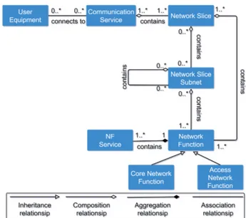
As shown in the Fig. 3, each UE might connect to several Communication Services (CSs). A simple example of this scenario is given by considering a 5G user who is connected to a Gaming Service while listening to music offered by a Streaming Service. According to 3GPP standards, each CS requests different requirements [11], such as minimum bandwidth, security level, maximum end-to-end latency, (non-guaranteed) QoS, and others. To better deal with these hetero-geneous technical constraints, these CSs consist of one or more customized Network Slice Instances (NSIs). Each NSI, in turn, may be composed of one or more Network Slice Subnet Instances (NSSIs), which might in turn consist of other NSSIs. Within this nested architecture, each NSI (or NSSI) has one or more functions attached to the core (e.g. PCF, AUSF, SMF, UPF) or to Access Network (AN) domain (e.g. Connection Mobile Control Function, Scheduler Function). Finally, on the lowest level, one function is conceived with a proper set of NF services, as already discussed.
Fig. 3: Interactions between 5G entities: Unified Modeling Language (UML)-based class diagram.
Looking carefully Fig. 3, we find five mapping levels for creating a complete virtual 5G environment, each one with its own characteristics and technical complexities to be implemented.
MAPPINGNF SERVICES INTONETWORKFUNCTIONS
The first mapping is the most technical one. At this level, the difficulty lies in how to program each function so that it
behaves exactly as expected. As already discussed, each func-tion is conceived with a customized sub-set of NF services that keeps a slice operational and efficient. The difficulty related to this mapping is imposed by the need of minimizing the resource allocation for each function. Intuitively, the greater is a sub-set of NF services within a function, the greater is the amount of physical resources that must be provided to install it. Clearly, an important work must be done on this level to find the right sub-set of NF services for each function and for each use case, assuring the operability and efficiency of each CS.
MAPPINGNETWORKFUNCTIONS INTOSLICES ANDSLICE
SUBNETS
Mapping functions into slices is another technical problem. In this mapping, each NF has its own minimal physical capacity request (e.g. CPU, RAM, storage) as well as its own capability (e.g. package treatment rate). The mapping at this level must also take into account the connection between each possible pair of functions that must be linked, as well as the required capacity and processing rate on each of those virtual links. In this level, the orchestrator entity is already aware of the sub-set of NF services within each function. As a result, mapping functions into slices offers to the orchestrator entity a catalog of well defined slice templates to specific and recurrent CSs. The problem for this mapping level is how to decide which function must be present in each slice and how to predict the quantity of each NF instance within a slice to better deal with the expected data rate throughout the system. It is important to mention that this level also refers to the mapping of functions into slice subnets, so creating NSSIs.
MAPPINGSLICESSUBNET INTOSLICES
After creating a slice subnet catalog as mentioned in the previous mapping level, the orchestrator entity might decide to create NSIs from a well defined slice subnet templates. This may be the case where a core NSI is created from an UP and CP slices , combined. Hence, from 3GPP’s point of view, those two last NSs are seen as slice subnet and the whole core as a slice. Notably, to do this type of mapping, well defined sets of slice subnet templates must be available in order to guarantee the deployment of a whole NSI.
MAPPINGSLICES INTOCOMMUNICATIONSERVICES
This fourth level mapping is less technical than the previous ones. It takes advantage that all slice templates are already cataloged and ready to be deployed. According to its hetero-geneous needs and expected data rate throughout the slice, each CS has a subset of possible slice templates to be mapped to. In this context, one may use matching techniques to better identify which templates are the most appropriated to a given set of CSs. It is worth noting that this mapping level can also be applied when slices are already deployed. In this context, each CS request might be mapped to an active virtual network.
MAPPINGCOMMUNICATIONSERVICES INTOUSER
EQUIPMENT
The mapping levels formerly described are related to the first phase of the life cycle of a slice [11]. This phase, called Preparation, deals with the design of each previous mapping level, as well as the pre-provisioning and network environment preparation. The second phase consists of installing all slices on top of a physical network and activating them. Then, a mapping of Communication Services into UEs must to be done as soon as a new request arrives. Next, in Run-time phase, all slices are already activated and each UE must be connected to the right CS. More technically, this mapping is essentially a mapping of UE into the right NSI. This is done after a registration procedure by the first AMF receiving the connection request. This function then interacts with NSSF. Based on orchestrator’s policy rules, NSSF is responsible to direct each UE to the right Communication Service. Hence, this last mapping level is essentially concentrated on NSSF, which must be connected to all AMF of other slices offered by CS Providers.
Clearly, a higher level of mapping can only be done if all lower ones are already concluded, creating a strong depen-dency between them. Additionally, each level in this nested arrangement has its own complexity and choosing the right mapping to offer a CS request is crucial. Hence, a trade-off between flexibility and readiness is imposed. Deploying Com-munication Services from the first level gives more flexibility to adapt a virtual environment to a new 5G CS with specific and unexpected technical constraints. However, this might be a very arduous work to be done for every single request. Along these lines, for those highly expected classes of CSs with well known technical constraints, creating templates to be available to a higher mapping level speeds up the procedure to build a virtualized 5G CS using network slicing techniques.
S
HARED ANDD
EDICATEDE
NVIRONMENTS The mapping problem rising in 5G described above appears as a novel multi-level embedding of network nodes. Jointly, addressing each mapping strategy involves a crucial point: how will each entity of the same level interact with the higher level instances? Isolation is a key aspect for network slicing and dedicated functions, for example, might be necessary to ensure that each slice operates independently, preventing the incorrect balance of resources between the serving slices. Additionally, security is another extremely important point in virtual environments. To ensure security and data routing control, partially or completely isolated slices with dedicated functions might be implemented.On the other hand, sharing a function is an interesting strategy to simplify virtual environment implementation and to reduce redundancies throughout the network. Due to the high programmability of NFs, some of them can be installed on top of physical resources to be shared by a set of slices. In addition, following 3GPP standards for 5GC, some NF instances must be common and shared between different slices. This imposition can be interestingly exemplified with NSSF. This function is responsible for mapping each UE to the right
slice serving a requested CS. In this way, deployed slices must share an interface with NSSF to keep it capable of making the right slice targeting.
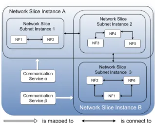
It is important to keep in mind that, as functions, a NSSI can also be shared by two or more NSIs, or it might still be entirely dedicated to a slice. Fig. 4 illustrates this concept and depicts a possible mapping for different Communication Services. Note that service α is serviced by NSI A, while service β is mapped to NSI B. In this example, NSSI 2 is a shared entity and is serving both NSI A and NSI B. From a holistic point of view, NSSI 2 can be interpreted as an access network serving two cores (NSSI 1 and NSSI 3), or the other way around, for example.
Fig. 4: Interactions between Slice and Slice Subnet Instances. Looking at the 5GC context, it is still possible to have several function mapping configurations for a set of slices that are dedicated to core networks [11]. As depicted in Fig. 5, the first case, which we have named Flat CN Mapping, could be a direct virtualisation of legacy technologies, where all CSs share the same core. This scenario may be an interesting strategy when the set of slices do not have very miscellaneous technical constraints related to latency, availability and iso-lation, for example. The second case illustrated by the same figure shows a scenario named Shared Control Plane Mapping, where slices share the same CP, while having their own UPs, with functions entirely dedicated to them. This configuration may be a solution for slices that require low latency, in which UPs should be as close as possible to UEs. Furthermore, cases of complete isolation might use a third configuration, named Hard Isolation Core Network Mapping. In this slicing, each CS has its own virtual core network. Finally, the last illustrated example presents a scenario where only a part of the CP is shared by two (or more) slices while another portion of it and entire UPs are dedicated. We have named this strategy as Soft Isolation Core Network Mapping. It is important to note that these configurations are meant to be easily adaptable to more than two Communication Services.
Following the assumptions presented by 3GPP, several other configurations may be implemented to better assure the estab-lished Service-Level Agreement. Hence, new configurations must be carefully studied in order to respect isolation and
Fig. 5: Network Core Mappings including Common Control Plane (C-CP) and Dedicated Control Plane (D-CP) systems.
security constraints as well as applying operators’ policies and strategies.
C
HALLENGES3GPP has been proposing a series of evolutions in the Core Network to better serve the upcoming 5G network. We summarized this work in this article with a particular view on function decomposition and related mappings, which seems to call for even more integration of SDN, NFV, and Network Slicing subsystems than what was commonlyanticipated. In-deed, new challenges are imposed to operators to ensure that future virtualized networks are successfully operational.
One of the main challenges is related to the first level of mapping. Managing the granularity of a function is a crucial point to minimize the use of physical resources. As a consequence, an intelligent entity is needed to provide the exact sub-set of NF services. What level this granularity is managed and which entity is responsible for it remain both open questions. In other words, will the dynamic creation of customized NFs be in charge of the NFs themselves, the orchestration entity or there will be a new NF dedicated to this end? A similar problem was addressed by [12]. In this work, the authors propose a flexible service composition in order to minimize the redundant functionality found in instances of different service functions (e.g. application and edge firewalls, load balancer, and proxy) throughout the virtual architecture. For this propose, they apply the microservice concept on service functions chains for re-architecting the NFV ecosystem. This interesting approach is directly related to the concept of NF services introduced by 3GPP, however there is no study proposing such an technique in functions related to 5G Core Network. Hence, this remains an open problem to be addressed.
Furthermore, for each new and uncontemplated use case, new mappings at each level must be performed, causing higher levels to depend intrincically on the lower levels. In other words, to map slice templates to CSs, for example, a complete function mapping work into slice must already be completed. Clearly, mapping strategies have a strong impact on slice deployment and how to model it. First, an intelligent framework to correctly distribute the flow of data throughout slices must be provided. This is due to the proposed scalability
for critical functions to handle highly dynamic data rate. In this context, defining the number of instances for each function within an slice is not a trivial work. Such a framework must be aware of the current state of the network to decide the exact time of scaling up and down some critical NF instances and to redistribute the flow among them in a intelligent manner. [13] presents an approach to address this problem, however the authors apply such framework only on one critical network function and do not give any instruction on how it could be implemented on two or more core functions at the same time. In fact, proposing such global framework is not a trivial task and remains an open problem to be addressed.
All these challenges must be overcome wisely and effec-tively, as the state of the system can change every second. In legacy technologies, such as 3G and 4G, the entire network system was designed for approximately ten years of use, with small variations and slow evolutions over the period. Contrarily, the 5G system is meant to be extremely flexible and still be able to offer a customized and complete virtual network in minutes for each Communication Service request. In this way, network designers and engineers have a laborious road to develop and apply techniques, algorithms, models, and approaches that guarantee the high efficiency in translating Communication Service demands into slices, doing all the necessary mappings, allocating physical and virtual resources, and activating, monitoring, and evolving each slice on 5G system.
A
CKNOWLEDGEMENTSThis work is supported by the french Agence Nationale de la Recherche (ANR), Project MAESTRO-5G ANR-18-CE25-0012.
I. R
EFERENCES[1] 3rd Generation Partnership Project, “Release 1999: Specifications,” Tech-nical Specification Group Services and System Aspects, 1999.
[2] M. Neruda and R. Bestak, “Evolution of 3gpp core network,” in 2008 15th International Conference on Systems, Signals and Image Processing . IEEE, 2008, pp. 25–28.
[3] 3rd Generation Partnership Project, “3GPP TS 21.101 V8.0.0 : Technical Specifications and Technical Reports for a UTRAN-based 3GPP system (Release 8),” Technical Specification Group Services and System Aspects , 2009.
[4] ——, “3GPP TS 23.214 V14.0.0: Architecture enhancements for control and user plane separation of EPC nodes (Release 14),” Technical Specification Group Services and System Aspects , 2016.
[5] ——, “3GPP TS 23.203 V11.9.0: Policy and charging control architec-ture (Release 11),” Technical Specification Group Services and System Aspects , 2013.
[6] ——, “3GPP TS 23.501 V15.4.0: System Architecture for the 5G System (Release 15),” Technical Specification Group Services and System Aspects , 2018.
[7] ——, “3GPP TS 32.291 V15.2.1 : Telecommunication management, Charging management, 5G system and charging service (Release 15),” Tech-nical Specification Group Services and System Aspects , 2019.
[8] ——, “3GPP TS 29.521 V15.3.0: 5G System; Binding Support Man-agement Service (Release 15),” Technical Specification Group Services and System Aspects, 2019.
[9] ——, “3GPP TS 23.502 V15.4.0 : Procedures for the 5G System (Release 15),” Technical Specification Group Services and System Aspects, 2018.
[10] ——, “3GPP TS 29.503 V16.0.0 : 5G System; Unified Data Management Services (Release 16),” Technical Specification Group Services and System Aspects, 2019.
[11] ——, “3GPP TR 28.801 V15.1.0: Telecommunication management; Study on management and orchestration of network slicing for next generation (Release 15),” Technical Specification Group Services and System Aspects, 2018.
[12] S. R. Chowdhury, M. A. Salahuddin, N. Limam, and R. Boutaba, “Rearchitecting nfv ecosystem with microservices: State of the art and research challenges,”IEEE Network , vol. 33, no. 3, pp. 168–176, 2019.
[13] I. Alawe, Y. Hadjadj-Aoul, A. Ksentini, P. Bertin, and D. Darche, “On the scalability of 5g core network: the amf case,” in 2018 15th IEEE Annual Consumer Communications Networking Conference (CCNC). IEEE, 2018, pp. 1–6.
B
IOGRAPHIESWESLEY DA SILVA COELHO ([email protected]) received B.E. degrees in Computer Engineering from Universit´e Clermont-Auvergne, France, in 2017, and in Industrial Engineering from Universidade Federal de Minas Gerais, Brazil, in 2018. He also holds a Master degree in Models and Algorithms for Decision Support delivered by Universit´e Clermont-Auvergne, France, in 2017. In 2018, he started his Ph.D program in Computer Science at Conservatoire National des Arts et M´etiers, France. His researches are related to 5G network design, modeling and optimization, and are carried out in collaboration with Orange Labs, Chaˆtillon, France.
AMALBENHAMICHE([email protected]) ob-tained a Ph.D. degree in Combinatorial Optimization from Paris-Dauphine University in 2013. She held a post-doctoral position at the French Alternative Energies and Atomic Energy Commission (CEA). She joined Orange Group in 2016 and is currently part of the Traffic and Resource Modelling research department at Orange Labs, France, where she works on optimization problems for future networks.
NANCY PERROT ([email protected]) received her Ph.D. degree in Applied Mathematics with a specialization in Operations Research from the University of Bordeaux1 in 2005. She joined Orange in 2005 to work as a researcher on several network optimization problems. Her current research interests are related to network virtualization, slicing in 5G networks and security in complex systems. She supervised several M. Sc. and Ph.D. students. She is currently a member of the Orange expert community Future Networks, the man-ager of the Mathematical Optimization research activities at Orange, and the leader of the ANR MAESTRO-5G project on the management of slices in 5G networks.
STEFANOSECCI[SM] ([email protected]) is professor of networking at Cnam, Paris, France. He received the M.Sc. degree in communications engineering from the Politecnico di Milano, Milan, Italy, in 2005, and a dual Ph.D. degree in computer science and networks from the Politecnico di Milano and T´el´ecom ParisTech, France. He held post-doctoral positions at NTNU, Norway, and GMU, USA. He was an Associate Professor with Sorbonne University-UPMC, Paris, France, from 2010 to 2018. He has also covered positions at NTNU, George Mason University, Fastweb Italia, and Ecole Polytechnique de Montr´eal. His current research interests are about network automation and control protocols. More info: http://cedric.cnam.fr/ seccis.