CRACK INITIATION AND PROPAGATION IN ROCK
by
PARVIZ FOROOTAN-RAD
Civil Eng., Tehran University
(1964)
M.Sc.C.E., Ohio State University
(1966)
Submitted in partial fulfillment of the requirements for the degree of
CIVIL ENGINEER
at the
Massachusetts Institute of Technology
June 1968
Signature of Author .... . . ...
Department of Civil Engineering, May i17, 1968 Certified by . . .. . . . .
Thesis Supervisor
Accepted by . . .
ABSTRACT
CRACK INITIATION AND PROPAGATION IN ROCK
by
PARVIZ FOROOTAN-RAD
Submitted to the Department of Civil Engineering on May 17, 1968, in partial fulfillment of the requirements for the degree of Civil Engineer.
Theories of crack initiation, propagation and bifurca-tion in perfect solids based on energy equilibrium criteria, elasticity theory considerations and particulate body mechanics are reviewed. Modifications of these and their applicability to rock are discussed. Different testing methods used to study the fracture characteristics of rock are reviewed; a bending method was chosen as most suitable for the purpose. A literature review on the effect of heat treatments on rock weakening are discussed. The principles of a continuous
duty, high powered gas laser as a heat source are described. The values of the fracture surface energy were determined for four different geometries of a granite specimen; the
results show that if a stable fracture is obtained, the value is independent of geometry. Results of the heat treatment and laser treatment studies on marble and granite show the thermal exposure causes a decrease in the value of ultimate flexural strength because of intergranular and transgranular cracks induced in the specimen.
Thesis Supervisor: Fred Moavenzadeh
A CKNOWLEDGEMENTS
The author wishes to thank Professor Fred Moavenzadeh for his excellent guidance, constructive criticism and constant supervision throughout the preparation of this thesis. The author further thanks Professor F.J. McGarry and Professor R.B. Williamson for their valuable and
helpful suggestions.
Sincere appreciation is also extended to Professor R.C. Hirschfeld, for many enlightening discussions and the United States Department of Commerce for providing financial
CONTENTS Page Title page 1 Abstract 2 Acknowledgments 3 Table of Contents 4 I. Introduction 7
II. Fracture of Perfect Solids 9
1. Crack Growth to Critical Size 9
a. Energy Equilibrium 9
b. Elasticity Theory Criterion 13
c. Particulate Body Mechanics 15
2. Propagation Velocity and Branching of Cracks 16
a. Energy Equilibrium 17
b. Elasticity Theory 18
c. Particulate Body Mechanics 19
d. Experimental Observations 20
III. The Fracture of Rock 22
1. Theories for Fracture of Rock 23
a. Modified Griffith Theory 23
b. Coulomb-Navier Theory 24
c. Mohr Theory of Failure 25
d. Modification of Coulomb.-Navier-Mohr
Theory 27
Page 2. Experimental Methods in Rock Fracture 27
a. Unconfined Compression 28
b. Compression with Lateral Pressure 28
c. Torsion 29
d. Punching 30
e. Hollow Cylinders Subjected to Axial
and Hydrostatic Loads 30
f. Disks Subjected to Transverse Load 31
g. Brazilian Test 32
h. Indentation 32
i. Tension 33
J. Bending 33
IV. Heat Treatment of Rocks 35
1. Weakening of Rocks 35
a. Macroscopic Scale Analysis 35 b. Microscopic Scale Analysis 36
2. Laser Treatment 39
a. Laser 39
b. Laser Radiation 40
V. Experimental Procedure and Materials 43
1. Testing Method 43
2. Testing Details 44
3. Materials, Equipment and Specimen Preparation 44 VI. Results and Discussion of Results 4 1. Fracture Surface Energy of Untreated Specimens 46 2. Fracture Surface Energy of Treated Specimens 48
3. Crack Propagation Observations
VII. Conclusions and Suggestions for Future Work
Tables Figures References
1. References on Fracture
2. References on Heat Treatment 3. References on Laser
Appendices
Appendix I List of Figures Appendix II List of Tables
Appendix III List of Additional References Page 52
54
56 106 110 113116
121 122 ~~_~_ _1_11~1~-11~______I. INTRODUCTION
The study of rock mechanics is a relatively new area, the importance of which has increased greatly in the past two decades. Several factors have been responsible:
1. The fast growth of the mining industry.
2. The increase in the number of projects such as dams, water tunnels, subsurface power houses, subways, automobile and railroad tunnels being built.
3. The increasing interest and demand for underground storage chambers for petroleum products, chemicals, food, and supplies.
4. The need for underground military installations.
The primary purpose of rock mechanics studies is to develop methods to predict the performance of various rocks under
differ-ent loading systems. This involves an analysis of applied loads, as related to rock failure, and the prediction of internal effects such as strain, flow, and microcracking. The internal effects may arise from residual stresses or from the application of external loads.
Knowledge of rock behavior is used'for two purposes: safe design of structures in rock, and for more economical methods of excavation. In the design area, more accurate knowledge of
the behavioral properties of rock will decrease the number of failures of structures on or beneath the earth surface. In excavation, knowledge particularly of the fracture characteris-tics aids the design of new machines and techniques for the con-struction • f tunnels and underground chambers.
Since the properties of rock are highly dependent on composition and internal structure it is usually necessary to test representative samples to determine the pertinent char-acteristics. Conventional methods of testing require large specimens and, if the rock is stratified, it is inconvenient _
to measure the strength for different strata. .A testing method that would utilize thin or small specimens would overcome these disadvantages. Further, it would be feasible to cut such
specimens from any desired strata.
Fracture in brittle materials is a consequence of crack initiation and propagation from regions where there are stress concentrations, hence it is desirable to investigate patterns of crack propagation and their major governing factors in rock. Thin specimens are useful for this purpose, too.
One goal of this study was to develop a technique to observe the fracture characteristics and crack propagation patterns in granite and marble. To achieve this;
a) -A suitable geometry for thin section specimens was determined.
b) A special three point bending apparatus was designed and developed.
c) The value of fracture surface energy obtained from these sections was correlated with that obtained from larger specimens.
d) The effect of notch depth on the propagation and branching of cracks was determined.
e) The influence of material type on propagation and branching of cracks was investigated.
f) Heat treated and laser treated specimens were studied to determine the effect of such treatments on the parameters governing the propagation and branching processes.
The following three chapters present surveys of litera-ture on the fraclitera-ture of perfect solids, the fraclitera-ture of rock, and heat treatment of rock. The balance of the report describes experimental work and its significance.
II. FRACTURE OF PERFECT SOLIDS
This chapter reviews the theories of fracture of perfect solids and consists of two sections: 1) crack initiation phenomena, where different approaches used to define crack growth to critical size in perfect solids are presented, and, 2) velocity and bifurcation phenomena, where analyses of the velocity and branching of moving cracks in perfect solids are discussed and also pertinent experimental data are presented. 1) CRACK GROWTH TO CRITICAL SIZE
The tensile strength of a perfect, homogeneous, elastic, isotropic, solid is of the same order of magnitude as its molecular cohesion. This is larger than the experimentally observed strength by a factor of 100 - 1000 (30,31). Accord-ing to Griffith (16), the difference results from the pres-ence of small cracks or flaws around which severe stress con-centrations develop when the solid is stressed. The theoreti-cal strength is attained in these small, highly stressed vol-umes of the material, even though the average stress which is usually measured remains low. In order to assess the effect of such cracks on the strength of the material, and to determine the mechanism responsible for the growth of the crack, one of the three following criteria can be used:
a) energy equilibrium, b) elasticity theory, or c) parti-culate body mechanics.
a, Energy Equilibrium
When a material is stretched, the distance between two neighboring planes of atoms is increased by an amount
propor-tional to the elastic energy stored 'in the specimen. This potential energy can provide the surface energy required for newly formed surfaces if the material fractures. However,
the presence of a crack changes the stress distribution from uniform to non-uniform and lowers the fracture strength of the material. The variation of fracture strength with crack depth in glass is a declining straight line on the log-log scale, as shown in Figure 1 (2). For simplicity, the Griffith analy-sis refers to the two dimensional problem of a plane plate with a stationary central crack of elliptical shape. By making the ellipse very sharp at its ends and assuming that Hooke's law holds, Griffith calculated the critical nominal stress under which the material fails using the Inglis analysis
(16). According to Inglis, the local stress at the tip of
such a crack is: 2C
CY 2c
-max p
where: amax = stress at crack tip, a = applied nominal stress,
c = crack half length,
p = radius of curvature at the crack tip. Calculating the stored elastic energy by using this equation, and equating it to the energy required by the newly created surfaces, Griffith obtained for the critical stress:
-. 2EY
c ~c(l-v2)
where: a = critical applied nominal stress that causes fracture,
E = Young's modulus of elasticity, c = crack half length,
Y = fracture surface energy, v = Poisson's ratio.
According to this theory, the strain energy of the system increases with increasing applied stress prior to initiation of crack growth. After initiation, however, the change in
strain energy of the system depends upon the magnitudes of the kinetic energy and the surface energy. The kinetic energy of the system is initially zero but at the critical stress when the crack begins to propagate, the kinetic energy starts
to build up and increases as the crack length increases. Figure 2 shows the general relation between kinetic energy and crack half length.
The locus of the stress and strain at the onset of crack instability is shov:n in Figure 3 (3). Fracture occurs when
the stress-strain curve of the sample intersects this locus. For a typical sample the point of intersection is in the region where the slope of the locus is positive. The possible dis-crepancy between the observed stress and that predicted by the Griffith equation is related to the angle between the stress-strain curve of the sample and the locus at the point of inter-sections As the length of the crack increases, the value
of this angle approaches 900, where the sample satisfies the Griffith criterion. This implies that, due to the difference in the strain-energy stored in the specimen prior to fracture, an initially small crack in a sample would have a high starting velocity while an initially large crack would have a low
starting velocity.
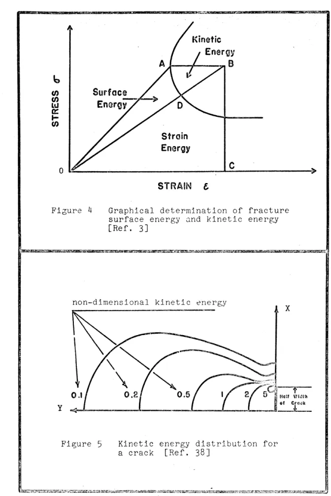
An interesting feature of this locus is that it can be
used for the determination of fracture surface energy and kinetic energy (3). Consider a sample containing a crack.of length 2c extended to fracture, and the ultimate stress maintained constant as the crack increases in length; the path followed is OAB as shown in Figure 4. The part of the work expended as surface
energy, the part expended as kinetic energy, and the strain energy of the system can be determined, at any time after the initia-tion of the crack, by measuring the corresponding areas identi-fied in Figure 4.
To obtain the solution for a moving crack, the Griffith criterion can be incorporated into the equations of motion (3). To do this it is assumed that the system possesses only poten-_tial energy up to the critical crack length point, and then
has both potential and kinetic energy beyond this point. The kinetic energy at any stage is the difference between the work done on the system and the increase in potential energy of the system. The relation between the length of the crack and the elapsed time is established from an expression for the kinetic energy of the system. The result is:
c t = (c-1)/2[a-(n-1) 1/2+ n gn 1(-l)/2+ [a-(n-1)]1122
n- n(2-n)
where the incorporation of the fracture criterion determines the value of n;
2
n = g and
c
co = initial crack half length, c = extended crack half length, t t= ime,
p = density of the material,
E = Young's modulus of elasticity, k = a numerical constant,
O = fracture stress predicted by Griffith Theory,
ao = observed fracture stress,
V = terminal velocity of the crack m propagation,
C C '
0
V_ = (2- )/ 2 E 2),
The Griffith criterion was extended to the solution of a two-dimensional crack in a three-dimensional medium by Sack (39) and Sneddon (44). Conditions of rupture were calculated for a brittle solid containing a number of plane circular cracks when one of the principle stresses acted normally to the plane of these cracks. This loading pattern was chosen based on the simplifying assumption that the tensile strength of the brittle material in one direction is not affected by the stresses at right angles to it. The highest stress that can thus be applied in a direction normal to the plane of the disk shape crack is:
TEY
c .2c(1-v2 )
where c = nominal stress applied perpendicular to the plane of the crack,
E = Young's modulus of elasticity, Y - fracture surface energy,
v = Poisson's ratio, c = radius of the disk.
This solution differs from Griffith's solution by a factor between 1.57 and 1.8 depending upon Poisson's ratio of the
mate-rial
(39,44).
b. Elasticity Theory Criterion
Another method to find solutions for an unstable crack is to use elasticity theory. The crack is ai d to be a nrow
slit which may be regarded as the limit of an ellipse with its minoj axis approaching zero. The stresses in the neighborhood of the tip of the crack are then calculated. The stress distri-bution near one end of the crack is not influenced by its dis-tance from the other end so the solution is obtained by consider-ing the case in which a crack of constant length is movconsider-ing through a plate. The problem of finding the stresses in the neighbor-hood of the crack tip then reduces to finding the stresses in a plate which is subjected both to a uniform tension and a
disturbance caused by the crack passing across the plate. This disturbance is represented by a system of elastic waves of
constant speed and form. The stress at the tip of the crack is given by:
T (p)(1 1 1
S y) - (- + ycos 2e) cos
-HY Y 2
- 2psin 20 sin -)] / (cos2 6 + y2sin 0)1
202 1 2
+ [2 pcos 20 cos -+ I(- + 8) sin 20 sin ] /
1+822 2
(cos 20 + 82 sin20)1
where a = stress in the vicinity of the crack tip,
T = nominal applied stress,
k = a small constant, X, = Lame constants, Y= - 2/c 2 Y 2/C2 Y=2 _ _
r,O = polar coordinates, tan 6, = Ytan e,
tan e2 = Btan 0,
cl = propagation velocity of longitudinal waves, c2 = propagation velocity of shear waves,
C = propagation velocity of the crack, H - (X + 2p) +
1+ 82
If the crack velocity is set equal to zero in this expression, it properly reduces to the Inglis solution for stresses around a stationary crack (45).
A very similar approach to the problem of a moving crack,
using the theory of elasticity, assumes a semi-infinite crack
propagating in an elastic medium (14). This method gives an
estimate of the force required to drive the crack. The two solutions agree quite well (14,46).
c. Particulate Body Mechanics
Three different treatments of crack propagation have beeh made by particulate body analysis. Cottrel (11), using dis-location theory, obtained a solution identical to Griffith's. Orowan (29,30), assumed that the smallest possible radius for the crack tip was the interatomic spacing and obtained a solu-tion identical to Griffit-1's e-cept for a numerii cal factor well within the approximations necessary in such analyses. The third approach (3!4 ,35,) resulted in a diiierenl solution. According to this theory, if a particle pair in
a particulate body is broken due to excess energy, the particles form new surfaces and the potential energy released is
con-verted to surface energy. The vibrations induced in these particles due to breakage of the bond between them generate elastic waves which also dissipate the elastic strain energy
causes a momentary cooling in the newly formed fracture sur-faces. However, both of the two vibrating particles remain part of the body and cannot move very far so they cause dis-turbances in it instead. Perpendicular to the new surface this propagates as a longitudinal wave which has a displace-ment of the separated particles. Along the new surface, the disturbance.propagates as a transverse wave, which has a dis-placement also in the same direction as that of the separated particles. The longitudinal waves impose a compression on the bonds of the body which were previously extended by the applied tensile stress; they thus relieve these stresses. The transverse waves, however, cause an additional tension on the unbroken bonds at the edge of the crack, increasing the probability that they will break. If the particles of the broken bond reform before the bonds at the new crack edge break, the whole process is merely an exchange interaction between bonds. If, however, the edge bonds do become broken before the previously broken bonds reform, the new transverse waves emanating from the latter prevent the broken bond from reforming. The fracturing process, therefore, continues by straining new bonds at the edge of the extended crack, and the new free boundaries develop as an irreversibly propagating
crack.
2) PROPAGATION VELOCITY AND BRANCHING OF CRACKS
The velocity with which a crack propagates is dependent upon the material, the stress pattern imposed on it, and the amount of energy stored in the system at the time of fracture
initiation. There exists a limit known as the terminal velo-city. This is a property of the material. If the energy available to the crack exceeds that sufficient to drive it at the terminal velocity, the crack will either oscillate or bifurcate, or it will propagate at the terminal velocity and the excess energy will appear in other forms. Again, the prob-lem can be approached on any of the following bases: a) energy
equilibrium, b) elasticity theory, c) particulate body mechanics, or d) experimental observations.
a. Energy Equilibrium
Agreement between theoretically calculated and experi-mentally measured values (38) for brittle cracks has suggested
that the terminal velocity is governed by the supply of kinetic energy to the crack field. Figure 5 shows the kinetic energy distribution for a crack of instantaneous length 2c.
If, upon the initiation of crack propagation, the dis-placements are immediately communicated to the outermost parts
of the specimen, then the crack may move with a very small terminal velocity. Stress waves, however, limit the volume oi material to which kinetic energy must be supplied because the communication of the displacements is limited by the
velocity of elastic waves. Figure 6 shows the effect of stress wave propagation on crack velocity (38). The terminal crack
velocity is given by:
V = 0.38 E 1
-p(1-v2 ) c
where • V = terminal crack velocity, E = modulus of elasticity,
P = density of the material,
c0 = original length of the crack, c = extended length of the crack,
It has been shown that the terminal velocity of a crack is J:ndependent of.the surface energy and also that the stress state in the material surrounding the moving crack is approxi-mately equal to the corresponding stress state in the static
case (26,38,46). Using these assumptions, the terminal crack velocity in a brittle material is found to be about 38% of sound velocity, E
b. Elasticity Theory
It has been predicted (46) that a crack of constant length propagating in a direction normal to an applied tensile stress may reach a critical velocity (about 60% of the velocity of a shear wave) at which point its path tends to curve. The change in diroction is caused by a redistribution of stress ahead of the crack tip. Figure 7 shows the maximum stress orientation ahead of the crack for different propagation velo-cities. Analysis of the semi-infinite crack case yields a terminal velocity which is 57% - 81% of the shear wave velo-city, depending on the value of Poisson's ratio for the
mate-rial (14).
Figure 8 shows the relation between crack speed and the
force required to maintain it: as the speed increases, the
force decreases (14). Thus, if a stress causes a crack to
initiate the crack may continue to propagate even though the
stress decreases. Catastrophic propagation may occur under a
This suggests that bifurcation must occur well before the velocity reaches that of Rayleigh surface waves, since at the higher velocities the cracking process tends to be
self-maintaining.
The solution for a two dimensional crack propagating in a three dimensional medium can be obtained by studying the displacements and stresses in a semi-infinite solid (8). In this, the solid is assumed to sustain:
1. A constant pressure, acting on an infinite strip, the width of vhich is symmetrically increasing from zero with constant velocity.
2. A pressure outside the strip such that the normal displacements of the surface outside the strip are
zero.
The terminal velocity of the. crack is independent of the value of surface energy (26) and in the analysis the surface energy term is assumed to be zero. This makes it
possible to assume that the crack nucleates from an infinitesi-mally small origin, and that it propagates with maximum
velo-city from its start. From the analysis it is concluded that a two dimensional crack moves in one plane, without
bifur-cation, at a constant velocity equal to the velocity of sur-face Rayleigh waves (8).
c. Particulate Body Mechanics
Using the particulate theory of fracture (34,35,36), the equation for the mean value of crack velocity based on the stress condition at the crack tip is as follows :
c2 E
V = - exp (-u kT)
where V = mean crack velocity,
c2= transverse wave velocity,
E = contribution of strain energy to fracture surface energy,
E = contribution of thermal energy of the
o body to fracture surface energy,
u = E /E o ,
k = Boltzmann constant,
T = absolute temperature in degrees Kelvin. This equation states that the terminal velocity of
propaga-tion is one-half the transverse wave velocity.
The major causes of bifurcation in terms of particulate
mechanics can be summarized as:
1. Broken bonds on both sides of the crack edge relieve the stresses in their neighborhood and prevent the propagation of the crack in the
same direction.
2. The orientation of the major principal stress usually changes from place to place in the
stressed body.
3. The configuration of the body produced by the propagating crack induces a change in the stress pattern so rapid that it is not in static
equili-briumi and elasticity considerations cannot be applied.
d. Experimental Observations
When thc stress condition in a sample exactly satisfies the Griffith criterion, the sample is in an unstable state and a crack begins to propagate if the stress increases
infinitesimally. Practically, the stress in such a sample continuously increases until it breaks. The value of
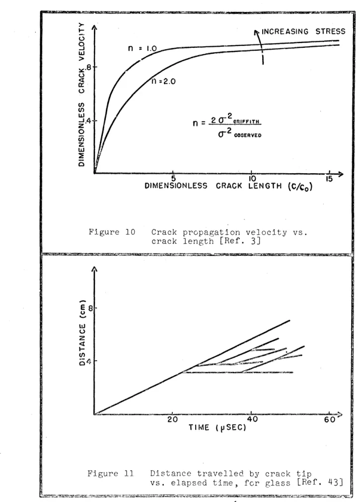
the fracture stress depends on the rate of load application and on the geometry of the specimen. Figure 9 shows the rela-tion between crack length and time elapsed after crack initia-tion. The time required to obtain a certain crack length
.decreases as the applied stress is increased. This difference is caused by the difference in initial velocities of crack propagation for different stress levels. The terminal
velo-city, however, is the same for all levels; Figure 10 shows this and also it shows that for lower stress levels, a longer crack has to be developed before the terminal velocity is attained.
The results of experiments on glass (42,43). confirm that the terminal velocity of all the cracks is the same, Figure 11, unless a crack slows down or stops because of bifurcation. The velocity of the crack propagation, however, is not uniform across the width of the specimen (40). Further, the velocity characteristics of each individual fracture are influenced by such factors as the degree of load relaxation occurring during the dynamic phase of the process.
The velocity history in a specimen subjected to bending stress is of different form. The crack initiates from and propagates through the tension zone but if the crack then approaches the terminal velocity, the neutral axis cannot
shift fast enough as the crack approaches it. To shift the neutral surface out of the way of the propagating crack
requires that the condensation wave s e itted from the propa-gating crack reach one end of the specimen and reflect back to the crack as dilatational waves. This takes considerably more time than is required for the transverse crack to reach the neutral surface. Figure 12 shows the result: the
velo-city decreases with depth in measurements on glass bars under flexural stress. The decrease is due to the fact that the crack has passed beyond the original neutral axis location.
III. THE FRACTURE OF ROCK
The solutions obtained for the fracture of perfect materials predict local failures in a perfectly homoge-neous, elastic, and isotropic material. However, all rocks are inhomogeneous, inelastic, and anisotropic. Thus the theories cannot be directly applied to rock although modi-fications of certain solutions do give satisfactory results. These modifications include the incorporation of the behavior of cracks in rocks under pressure (23), and the assumption that local failures in rock can occur simultanecusly in different locations.
If the analysis is done on a large or macroscopic scale, the rock may be assumed homogeneous and the flaws randomly oriented. It also can be assumed that the density and the size of existent flaws are uniform .throughout the rock speci-men. With these assumptions, Coulomb type failure theories
can also be successfully applied to predict the fracture of rock if necessary modifications are made, taking into account
the effect of flaws and imperfections. This is accomplished by assuming a low tensile strength for rock without any refer-ence to its cause: the presence of prior flaws and imperfec-tions, Further, most roc fracture theories have been developed and improved to explain certain phenomena previously observed in tests; thus the testing methods play an important role in
the study of rock fracture.
This chapter has been divided into two sections: 1) theories for fracture of rock, where theories which have been used in the literature to predict failure of rock are discussed, and 2) experimental methods in rock fracture, where- the different testing methods used to determine the
fracture characteristics of rock are reviewed, to identify * the application of theories and to clarify the testing method used in the present study.
1) THEORIES FOR FRACTURE OF ROCK
The following theories have been used to predict the fracture characteristics of rock:
a. Modified Griffith Theory, b. -Coulomb-Navier Theory,
c. Mohr Theory,
d. Modified Coulomb-Navier-Mohr Theory. A brief description of each follows:
a. Modified Griffith Theory
The crack propagation theories discussed in the pre-vious chapter assumed that no forces are carried across the faces of the crack. For rock, however, it is possible for cracks to close, and carry normal and shear stresses, through friction (23,29). These secondary stresses will tend to in-crease the strength of the rock by reducing the stress con-centration at the tips.of the crack from the value it would have if the friction stress did not exist.- The failure con-dition for such a specimen is:
P(a, + i - 2c) + (Ci - o,)(l + 2)12 = 4T (1 - C)112 O where a1,o3 = external normal stresses,
= coefficient of friction for the crack surface,
a= stress normal to the crack required to .c close it,
T = tensile strength of the rock.
0
If the applied stress is simple compression in one direc-tion, and if a= 0, the above equation reduces to:
0O 4
To
1
- (+ 2)1where C = compressive strength of the rock.
Combining this equation with the preceeding one results in a straight line relationship between two external normal
stresses (29).
b. Coulomb-Navier Theory
The Coulomb-Navier Theory postulates that failure will occur in a material when the maximum shear stress on a plane in the material reaches the shear strength, and that the normal stress acting across the plane increases itsfailure resistance
in proportion to the magnitude of the normal stress. The
shear strength is given by (29):
c1 + 0 3 0 - a3
So 2 2 (sin 2e + Pcos 28)
where S = shear strength of the material, y = coefficient of internal friction, CalY = applied normal stresses,
8 = inclination of the shear plane.
The maximum shear acts on a plane whose orientation is defined 1
by tan 20 = and its value is:
_
a
3Smax max 2 [ + (P2+1) ] + -2 [p - (p2+1) ]
The criterion for failure in tension is obtained by
substituting a T and 3 = 0 into the above equation:
T
o [ + (2+1) 21 S
2 max
The criterion for failure in compression is obtained by
substituting ao =0ndo , = - to the equation: o
-C o
- (12+l)I ] = S
2 max
Combining the above three equations results in a straight line, DE, in Figure 13, described by:
1 3
- 1
T C
o o
According to the Coulomb-Navier Theory, if the material experiences stress conditions outside the area DEB, it fails.
c. 'Mohr Theory of Failure
This is based on the earlier Coulomb concept of failure as a sliding action along planes inclined to the direction
of principal stresses. The resistance to sliding consists of two parts: a constant shearing strength, or internal co-hesion, and a frictional resistance which is proportional to
the normal stress acting across the plane of sliding. Analy-tically, the Coulomb Theory states:
(j1T + )ma = S
where S = ultimate strength in shear, p = internal friction coefficient, a = normal compressive stress, T = shear stress.
The Mohr Theory is a generalization of the Coulomb theory; it states that the material acts as a homogeneous body and
that there is a relation between the normal stress and the shear stress in any plane which governs the resistance of. failure along that plane.
According to the Mohr Theory a material will fail when (15):
(o+o )
(+2r
3- 1)
{on- 2 + m2(2
1- 2 2 2
where: ,sa 2, 3 = externally applied stresses,
= strength of material in axial loading, = shear strength of the material,
m = direction cosine of the plane being studied.
Graphically, any material whose stress state falls outside the outermost circle, in Figure 14, will fail; the plane of the failure can be determined by this method, both graphically and analytically. Failures under tension are represented by circles on the positive side of the normal stress axis. Failures under compression are represented by circles on the negative side (Figure 15). Similarly, the graphical representations of shear and combined loading are circles of different diameters with
their centers at different points on the normal stress axis. The failure is represented by the points lying on.the envelope
of these circles (45). Using the Coulomb Theory of internal friction, this envelope is represented by two straight lines tangent to the circles; Mohr's generalized theory results in a
curved envelope. The failure condition in terms of two normal stresses can be represented graphically as shown in Figure 16. If the applied stress state is defined by a point outside the shaded area, the material fails.
d. Modification of Coulomb-Navier-Mohr Theory
Based on experimental evidence a modification of the
failure envelope (13, 32, 33) can be made. Although the
analytical requirements for this modification are not always clear, it is widely used because of the simple graphical
representation. To construct the envelope, two lines tangent
to the uniaxial compression circle are drawn with the slope
equal to the angle, 4 , of internal friction of the material.
The envelope consists of these two tangents and a tension cut-off line drawn tangent to the uniaxial tension circle; see Figure 17. Available data show that the Coulomb-Navier-Mohr Theory of fracture can describe the results of the
compression tests adequately but cannot provide a realistic description of tension or torsion tests. The modified theory, however, represents fully the results of three simple tests:
shear, tension, and compression. In essence it states that
a brittle material fractures on either the plane where the
shear stress reaches a critical value or on the plane where
the maximum tensile stress reaches a critical value, which-ever occurs first.
Another graphical representation of this theory is shown in Figure 18. The shear stress condition is represented by
the inclined line BC and the tension condition is represented
by the tension cut-off AB. The results obtained using this
theory generally agree very well with experimental data for
brittle materials, including rock (32,22).
2) EXPERI'MEINTAL PETHODS IN ROCK FRACTURE
Rocks ax:e relatively hard to machine so the method used
in any experimental study should employ simple specimens.
Depending upon what characteristic is sought, usually a
particular method and specimen are used. Thus, several
methods have been developed, each suitable for a certain type of measurement.
The following methods are discussed in this section: a. unconfined compression, b. compression with lateral pressure, c. torsion, d. punching, e. hollow cylinders
sub-jected to transverse load, g. Brazilian splitting test, h. indentation, i. tension, and j. bending.
a. Unconfined Compression
This is the oldest method for measuring the strength of rock (19,20,21,32,33). The common practice is to use cylin-ders with a length-diameter ratio of 2:1 although the actual dimensions of the cylinders have shown an effect on the fail-ure pattern; the strength and the inclination of the fractfail-ure plane are higher in short samples (25). One difficulty in this method of test concerns the degree of lubrication of the end plates which has a pronounced effect on the mode of speci-men failure. With lubricated end plates the macroscopic fail-ure cracks occur parallel to the axis of compression (Figfail-ure 19). If the Coulomb-Mohr Theory is used to analyze the con-dition, the angle of internal fraction of the rock sample is found to be 90 degrees. This value is much larger than ordinary. With unlubricated plates, however, the cracks form at oblique angles to the axis of compression. Therefore, it appears that although the Coulomb-Mohr Theory is excellent for predicting fracture loads, it is not useful for predicting the direction of the failure planes.
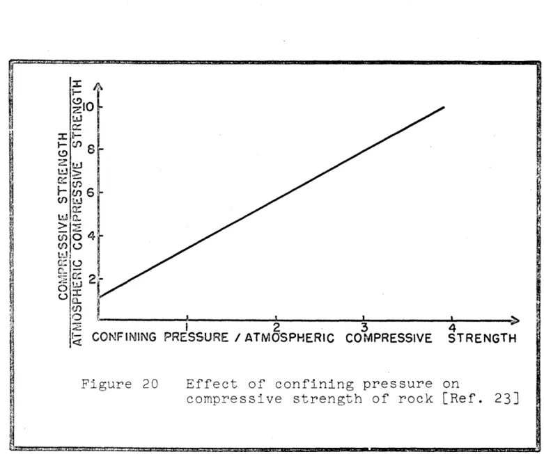
b. Compression with Lateral Pressure
This method simulates a more complex stress condition. The general effect is shown in Figure 20. The assumption that cracks close under a confining pressure and thus contri-bute to the strength of a rock specimen has been verified by experimental data (23). Further, despite the unconfined
compression test results, the fracture angles for specimens failed by compression and lateral pressure agree- very well
c. Torsion
A cylindi'ical bar of a brittle material subjected. to
torsion usually fractures in a single plane. This plane intersects the surface of the cylinder in a helix inclined at an angle of 45 degrees to the cylinder axis. The helix is perpendicular to the direction of maximum tension.
If a cylindrical specimen is subjected both to a torque and a confining pressure, the principal stresses are (20):
1(P + + - 2 + 4T2 12 1 2 a o 2 a o a 2 = P 0 S=(P + P ) 1 p )2 + 4T 2 112 3 2 a o a where T= 2M/a 3,
a = radius of the cylinder,
M = applied torque, P = confining pressure, Pa = axial pressure.
As a result of the confining pressure the tensile principal stress is reduced and the compressive principal stress is
increased. Under these conditions, the torque can be
in-creased to a higher value and the angle of the helical cleavage plane also increases.
d. Punching
In this method a small disk is punched out of a plate which usually is also a disk of larger diameter (19). The stress system approximates simple shear so a well defined disk is punched out. The periphery of the specimen can also be under a confining pressure to obtain a state of combined
stresses, if desired. This method is useful when measure-ments on anisotropic materials are to be made: specimens can be cut in the principal directions where the shear strength is to be determined.
e. Hollow Cylinders Subjected to Axial and Hydrostatic Loads
If a hollow cylinder is subjected to an axial load, an internal pressure and an external confining pressure (20), the radial and tangential stresses are given by:
2 [P - p2 P + (P. - P )(a - 1 c 2 r r u (1 - p2) 2 [P - p2P - (P. - P )(a ci i c 2 (1 - p2)
where r = radial stress, 0
e
= tangential stress,p = ratio of internal to external radius, Pi = internal pressure, P = confining pressure, P = axial loading, a r,0 = polar coordinates, a = inside diameter.
Several different fracture modes can be obtained by varying the three applied loads.
f. Disks Subjected to Transverse Load
In this method disks are prepared with a central hole and then tested in diametral compression. From the results the tensile strength of the rock can be calculated (37) as follows:
P - (6 + 38p2) 7rta
where P = tensile strength, W = load at failure, t = thickness of disk, a = radius of disk,
p = ratio of the internal to external radii. Most specimens fail by a crack running vertically through the central hole. Sometimes this is accompanied by secondary cracks. Basically four different types of crack pattern can be distinguished. Figure 21 shows these:
1. single fracture 2. S shaped fracture
3. branched fracture
4. cross shaped fracture.
The load at failure is a function of the orientation of pre-existing flaws and defects with respect to the direc-tion of the applied load. To confirm the existence of such a preferred orientation, point load tensile testing can be performed on solid disks of the same material. In this, a
compressive load is applied to the center of a disk specimen by means of two opposing hemispherical indentors, Figure 22. Failure generally occurs as a single fracture bisecting the disk parallel to the axis of loading. The applied stresses are symmetrical about the loading axis, and if the rock is isotropic, failure will be random. The failure for most rocks, however, has a preferred orientation (21)).
g. Brazilian Test
In this method, a solid disk is transversely loaded to fracture. The principal. stresses induced to such a specimen
(1) are: -P MN + 2R2N a - ( ) 1Rt MN + 2R2L -P MN - 2R2N 03 wRt MN + 2R2L where M= x + + R N 2 2 R2 N=x +y -R, 2 2 2 L =x -y + R , R = radius of disk, P = applied load, t = thickness of disk.
Fracture usually initiates at the exact center of the disk but after the initiation of the main crack some secon-dary cracks start forming. These are shown in Figure 23. In this method, the load at failure is also a function of orientation of the direction of pre-existing flaws.
h. Indentation
Classically hard brittle materials such as rocks become ductile during indentation or under confined compression. Further, the deformation caused by indentation of several
fine-grained crystalline rocks has been found microscopically to be the same as the deformation of these rocks in the ventional compression test carried out under moderate con-fining pressure (4). From the analysis of various microscopic and macroscopic observations, however, it has been concluded
that the apparent ductility of rock is more likely due to
systematic microfracturing on a scale too small to be observed, rather than due to slip (4).
The indentor is a diamond pyramid which is forced against the surface of the rock. The force acting on the indentor divided by the area of indentation is called the hardness. Hardness is thus the average normal stress applied to the surface of the specimen by the indentor. The strength of rocks estimated from hardness testing is approximately that measured in conventional tests.
i. Tension
Due to the difficulty of fabricating and testing tensile specimens, less attention has been paid to the direct appli-cation of tensile stresses. Most testing of rock, in tension and/or in shear, is done indirectly, as some of the previous techniques illustrate.
j. Bending
This method has not been used very widely for the study of fracture of rock despite its ease of operation. If a rock beam is loaded at midspan, it is very unlikely that the speci-men will fail exactly at its center. Instead, failure occurs where a combination of the prior crack length and the applied
stress imposes the most severe condition (18). Due to geometry and the energy storage characteristics of the specimen, the fracture is always a catastrophic one, even if testing is performed with a hard machine. The total elastic energy
stored in the system at the time of fracture initiation is the sum of the energy stored in the specimen and the energy stored in the apparatus, Figure 24. The stored elastic energy is dissipated in the fracture process. If it is greater than that required to form two new surfaces, the fracture is catastrophic (Figure 25) and the excess energy
is released in other forms: kinetic energy of fragments for example. However, if the elastic energy is smaller than the energy required for the formation of new surfaces, additional work is required to propagate the crack and the fracture is
stable.
The energy required to fracture the original test piece and create two new surfaces (28) is given by:
U = 2AY
where y = fracture surface energy, A = nominal cross section, U = required energy.
Measurement of the fracture surface energy from the
force-deflection curve is accurate only for stable fractures. To avoid the usual catastrophic fracture in bending, an arti-ficial crack is introduced on the tension side of the specimen, at midspan, and a stable or semi-stable fracture (Figure 25) is obtained. In this case, the calculation of fracture sur-face energy from the force-deflection diagram becomes valid. The method has proven to be a most convenient one to use
for determining the fracture surface energy of rock ,materials.
IV. HEAT TREATMENT OF ROCKS
Q
The use of heat in breaking rock has been known from antiquity. Generally the results of quenching after heating have seemed to obscure the fact that heating alone is
effec-tive so the study of just heating effects became secondary to the development of combined heating and quenching methods. Heating of rock can use conventional methods such as torch and flame jets or more unusual devices such as a laser which provides radiation of uniform wavelength. Both methods are discussed in this chapter.
1) WEAKENING OF ROCKS
Most rocks are weakened by heating and do not regain their strength after cooling. The weakening is achieved at temperatures much lower than the melting point. Numerous attempts have been made to assess the effectiveness of heat treatment in various heating and quenching cycles. Basically, two different approaches are used:
a) On a macroscale where the material is assumed to be completely homogeneous and the damage is due to thermally induced shock and the resulting stress distribution.
b) On a microscopic scale where the material is recognized to be granular and its response depends upon the character-istics of the constituent grains and their interactions. a. Macroscopic Scale Analysis
The fracture of rock on this scale is caused by thermally induced stresses which exceed the ultimate strength of the rock. The parameters affecting the thermal shock resistance of rock are strength, modulus of elasticity, Poisson's ratio, coefficient of thermal expansion, thermal conductivity,
specific heat,porosity, and density. For laboratory tests,
the size and shape of the specimens also affect the results as do the heat application procedure and any quenching experi-ence.
Since on this scale the rock is assumed to be homogeneous, the only weakening process which may operate is the develop-ment of stresses due to the temperature gradient present in
the rock. A crack initiates at a point where the stress exceeds the ultimate strength of the rock. If the elastic energy stored in the specimen is sufficient to drive the
crack through the specimen, it will fracture catastrophically; otherwise, the crack will stop after the stored energy is
exhausted.
b. Microscopic Scale Analysis
On the microscopic scale several mechanisms have been suggested (52) as responsible for weakening of rock due to heating. In almost all cases, a combination of two or more of these mechanisms can be identified in the heat treatment. These include gross chemical changes, gas or water pocket expansion, spalling and anisotropic thermal expansion.
Gross Chemical Changes: Good evidence exists that gross chemical changes do not occur in certain rocks such as marble (52) but such changes have been observed in heat treated
quartz (61). The latter are believed to be molecular in nature. For example the ease of crushing heat treated
specimens of quartz with one's fingers is cited as an indica-tion of an internal debonding caused by heating (61).
Gas or Water Pocket Expansion: These are usually accompanied by fragmentation of the specimen and by the
noise of small explosions. When such behaviors are observed during heating, this mechanism is considered responsible for weakening of the rock.
Spalling: Spalling is caused when various rocks have low thermal conductivity and appreciable thermal expansion.
It depends on the temperature gradients established, which are determined by the heating rate. Spalling could also be
caused by a high anisotrophy and/or low thermal conductivity. It has been observed (59) that rocks containing abundant
quantities of quartz are highly spallable.
Anisotropic Thermal Expansion: Differential thermal expansions of adjacent grains in rock can cause separations along the grain boundaries. However it has different conse-quences for isotropic and anisotropic materials. If the rate of heating of an isotropic material is slow enough to
avoid a large temperature gradient, each grain expands equally in all directions and there is no differential movement
among them. Further, on cooling, the rock returns to its
normal size and shape. If the rate of heating is rapid enough to produce a large temperature gradient, some grains expand more rapidly than others resulting in differential movement which may cause the formation of intergranular spaces.
When an aggregate of anisotropic grains is heated, the grains expand differently in different directions pushing
each other apart, creating open voids. Upon cooling, the openings do not quite retrace their previous movements, leaving some spaces unfilled and causing a permanent change in dimensions (47). If the aggregate is heated again, an additional permanent expansion is developed although the latter is not so large as the first one.
The separation caused by expanding grains is dependent upon the orientation of one grain relative to its neighbor, and the grain pairs having the greatest difference in stress orientation are subjected to the greatest shear at any given temperature. Therefore, they are the first to fail when the temperature is raised. As the temperature increases and more bonds are broken, only the bonds with less
misorienta-tion remain. This requires successively higher temperatures
to achieve successive shear failures at grain boundaries and eventually a point will be reached where no further effect can be observed.
In most of the possibilities listed, rupture at the grain boundaries seems to be a major factor, thus knowledge of the nature and behavior of grain boundaries seems desirable.
Most of the work which has been done on intergranular bonding, however, has been directed towards metals, with little or no attention to rock. Various models have been suggested. Mott
(70) proposed that the boundaries consist of islands of good fit and areas of bad fit between the lattices of adjacent^ grains. Ke (62) mentioned that boundaries consist of a concentration of lattice vacancies or disordered groups.
Brown (52) described the boundary as a series of dislocations of one type or another. Grain boundaries are frequently
very strong and thus cracks developed during heating or
mechanical testing do not always follow intergranular paths. With metals this is much more common than with rocks since rarely in metals does one find the extreme difference between adjacent grains that are possible and normal in rocks. For example, two metals rarely differ from each other as radically as quartz differs from a feldspar, yet these two minerals
are associated in granite in which very little intergranular fracture is observed in fractured specimens unless heat treat-ment has been applied.
Other mechanisms such as metallic type brittle fracture, phase transformation, intergranular corrosion, anisotropic
heat transfer, strengthening of grains by annealing, and
diffusion of impurities into grain boundaries are'also suggested in the literature as possible mechanisms responsible for rock weakening. It appears, however, that most such, although
/ responsible for weakening in other materials especially metals, can be dismissed or their effects can be considered secondary for rock (52).
2) LASER TREATMENT
The invention of the laser and its subsequent developments have provided science and industry with a new and powerful
tool. The term "laser" is an acronym for "Light Amplifica-tion by Stimulated Emission of RadiaAmplifica-tion". Basically, a
laser is a device which converts energy into a highly intense and narrow beam of light or electromagnetic radiation. Prior to discussion of use of laser radiation in the fracture of rock the principle of laser operation will be reviewed. a. Laser
Atoms of a material may occupy any one of many discrete or quantum levels of energy, depending upon the temperature of the material. If the system is in thermal equilibrium, most of the atoms will occupy the lowest possible-energy levels, where they are referred to as being in the ground state. They can be excited to higher energy levels, excited states, by absorbing energy from some external source. This may be in the form of heat, light, or other types of radiation. Atoms that are in an excited state will relax to a lower
energy state by releasing some of the absorbed energy. Such energy release is the basis for the operation of lasers. Mate-rials research and research in other fields related to laser have led to a variety of materials which will produce laser action; these include hard crystals, gases and gaseous mix-tures, plastics, glasses, semiconductors and liquids. Many of these materials may be operated in either a pulsed or a continuous mode.
In pulsed lasers, electric energy is stored in capacitors and then it is discharged in a gas filled flashlamp, resulting in an intense flash of white light. The laser material is placed where this light can be absorbed most efficiently.
When sufficient energy is absorbed by the material, its
characteristics change and it becomes an amplifying medium (80).
The optical cavity is developed by placing two highly reflec-tive surfaces at the ends of the laser material. One of these surfaces is slightly transparent and the other is totally
reflective. In relaxing to the lower energy level, the atoms emit photons which are principally directed along the axis of the laser material. The photons produce a wave of light which grows in amplitude until it reaches the semitransparent reflecting surface. Some of the light passes through the surface while the remainder is reflected to undergo further amplification. When the light reaches the totally reflecting surface, it reverses its direction and the process is thus repeated. The light which has been amplified but is not directed along the axis of the material, leaves the laser material through the sides of the cavity. In gas lasers where the output can be either pulsed or continuous, the
excitation is accomplished by running a cold cathode discharge in a flowing gas mixture. In general, the gas laser tubes are constructed with pyrex tubing which is cooled by means of a water jacket. Further, the dissociation of the molecu-lar gases, which is due to emission of photons from the gases, requires a flowing system of gases in the tube.
The output of the laser is in the form of a narrow beam of light or electromagnetic radiation. In addition, the output is essentially coherent in both space and time: all wave fronts of the light are perpendicular to the direction
of propagation and there is a definite phase relationship between the wave fronts, or they follow each other at regular
intervals (6).
b. Laser Radiation
There has been a wide interest in the laser from an
application point of view because it has a unique set of
capabilities: a) output is coherent, b) high frequency,
-c) monochromatic or narrow spectral line width, d) well collimated beam, e) high power density, and, f) continuous or pulsed operation. Many practical applications of the laser also depend upon the fact that the beam may be focused
to a small spot with simple inexpensive equipment.
The radiant energy delivered to a surface is consumed in one or more of the following processes: a. reflection, b. heating, c. boundary interaction, d. phonon genera-tion, e. acoustic phonon generation and f. reradiation.
The relative magnitudes of the different energy consump-tions depend strongly upon the thermal and optical properties of the material exposed to the radiation, as well as on the characteristics of the laser. The development of boundary interaction, such as radiation pressure, or other effects that may develop shock waves, has not been observed in the
experiments performed. Further, phonon generation and acoustic phonon generation have been observed only in materials that
are transparent to the laser wave length. Thus the mechanisms by which the laser energy is consumed in rock are heating, reradiation and, to a much smaller extent, reflection.
When a rock specimen is exposed to the laser beam the temperature of the exposed surface suddenly increases and a temperature gradient is developed. The rise in temperature and the development of the thermal gradient across the speci-men causes two types of stresses. Neighboring grains, due
to differences in orientation, will expand unequally and the thermal gradient will cause a stress field which assists in fracturing the specimen. Either or both of these stresses may be responsible for the weakening and eventual rupture of the specimen.. Since the laser energy is almost totally
absorbed by the rock specimen, a large temperature gradient will be developed in a short time, causing failure. The
misorientation of two neighboring grains located at the surface __ _~I_
of the specimen will also cause spalling. If the temperature of the exposed area is increased by increasing the exposure
time, the mechanisms already mentioned will be accompanied by partial melting of the exposed zone. The energy lost
will increase because of heat reradiation from the incandescent molten zone. If the temperature further increases, some of
the material which has melted will evaporate. It is postu-lated (81) that with very high power intensities and poor thermal conductivities, an internal explosion may develop, shattering the material.
If lasers are to be used as an aid to excavation, it is desirable to keep the temperature below melting so the rock is only weakened. Melting is economically unattractive and technically unnecessary, since extreme weakening occurs before melting takes place.
V. EXPERIMENTAL PROCEDURE AND MATERIALS
A review of the literature shows the most suitable testing method to be used both for measurement of fracture surface energy and for crack propagation observations is
the bending technique. With it the value of fracture surface energy for beams of size 1 x 1 x 12 inches and .1 x 1 x 4
inches and two intermediate sizes were measured for different notch depths. The crack propagation patterns were observed for different notch depths in marble and granite specimens. They were also observed for heat treated and laser treated specimens of marble and granite. In this section the experi-mental procedures and the materials used are presented.
1) TESTING METHOD
Due to the presence of flaws and imperfections, rock exhibits its lowest strength in tension and fails when the maximum tensile stress reaches the ultimate strength. Testing methods which produce complex stresses in the specimen obscure
this fact and make the analysis of crack propagation more difficult. Most methods also require fairly large specimens, which are inconvenient to prepare. In the bending method,
the stresses acting on the specimen are tensile and shear below the neutral axis and compression and shear above it. By making a notch at the midspan, the value of the tensile
stress is greatly increased, locally. Thus the crack initiates under essentially pure tension. In a properly chosen specimen
containing a notch of the right size, the tensile stress at midspan reaches the ultimate strength of the rock before the strain energy stored in the specimen is sufficient to drive the crack to the top of the specimen. This ensures the pro-duction of a stable crack which is required for accurate
calculation of the fracture surface energy. Thus the bending method was selected for this study.
2) TESTING DETAILS
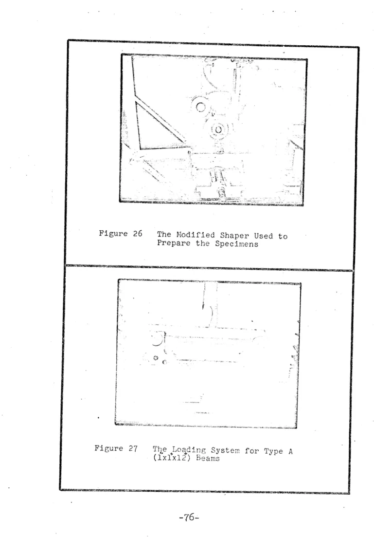
The specimens were tested in flexure with a concentrated load applied at the midspan in the Instron Universal Testing Machine using specially designed adaptors. The 1 x 1 x 12"
beams were tested on a 10" span (Figure 27) and the 0.1 x 1 x 4" beams were tested on a 3" span. The beams that were
0.1" thick were tested in.a special apparatus to prevent side motion of the beam during testing (Figure 28). The testing machine is a "hard" one which applies a constant rate of deflection. The loads due to the imposed deflection are recorded automatically. The area under the load-deflection curve is the work done by the machine to break the beam and to create the new surfaces. The fracture surface energy is then obtained by dividing the energy by twice the remaining cross-section of the beam at the point where it was notched.
To find the effect of notch depth and material type on the crack propagation patterns created, specimens were notched to 0.25", C.5", and 0.75" and then tested at the cross-head rate of .02"/min. Using time lapse photography with a camera having a maximum speed of 64 frames per second, pictures of the crack propagation patterns were taken for subsequent examination.
3) MATERIALS, EQUIPMENT AND SPECIMEN PREPARATION
The tests were conducted on specimens of Chelmsford (Mass.) granite and Danby (Vt.) marble. The properties of these rocks are given in Table 1. The rocks were received in the laboratory in the form of 1 x 1 x 12" beams.
Four different geometries of beams were used in this study and for each geometry, tests were conducted on differ-ent.notch depths. The beam geometries were as follows:
Type A 1" x 1" x 12"
Type B 1" x 1" x 4"
Type C 0.5" x 1" x 4"
Type D 0.11" x 1" x 4"
The notching and/or cutting of the specimens were done by a modified horizontal shaper (Figure 26).
To heat-treat the beams, they were placed in an electric oven set for 10000F., and kept there for 50 minutes. The specimens were cooled to room conditions after removal from the oven and tested within 24 hours.
Other specimens were exposed to laser radiation for five seconds (Figure 29) producing a total exposure of 600 watts. The specimens were then cooled to room conditions and testing was done within 24 hours after exposure.
![Figure 6 Effect of stress wave propagation on crack velocity [Ref. 38]](https://thumb-eu.123doks.com/thumbv2/123doknet/14511642.529821/64.918.138.815.97.1082/figure-effect-stress-wave-propagation-crack-velocity-ref.webp)
![Figure 8 Tensile stress vs. crack propagation velocity [Ref. 14] 3: J cr Q-2 2 CrI n = .wo 00 0- 00"ERfVED z -J 8 INCREASING STRESS 06 z 01.9 Z 2 U n= 2.0 5 10 v, t 15 DIMENSIONLESS TIME](https://thumb-eu.123doks.com/thumbv2/123doknet/14511642.529821/65.918.123.819.93.1067/figure-tensile-propagation-velocity-erfved-increasing-stress-dimensionless.webp)
![Figure 12 Fracture Velocity vs. Depth for a Bar in Bending [Ref. 40]](https://thumb-eu.123doks.com/thumbv2/123doknet/14511642.529821/67.918.172.819.87.1087/figure-fracture-velocity-vs-depth-bar-bending-ref.webp)
![Figure 15 Failure envelopes as suggested by Coulomb and Mohr [Ref. 32]](https://thumb-eu.123doks.com/thumbv2/123doknet/14511642.529821/68.918.123.815.98.1070/figure-failure-envelopes-suggested-coulomb-mohr-ref.webp)

![Figure 24 Schematic of' Bending Test [Ref. 28]](https://thumb-eu.123doks.com/thumbv2/123doknet/14511642.529821/75.918.105.821.92.1056/figure-schematic-bending-test-ref.webp)