HAL Id: emse-01130782
https://hal-emse.ccsd.cnrs.fr/emse-01130782
Submitted on 12 Mar 2015
HAL is a multi-disciplinary open access
archive for the deposit and dissemination of
sci-entific research documents, whether they are
pub-lished or not. The documents may come from
teaching and research institutions in France or
abroad, or from public or private research centers.
L’archive ouverte pluridisciplinaire HAL, est
destinée au dépôt et à la diffusion de documents
scientifiques de niveau recherche, publiés ou non,
émanant des établissements d’enseignement et de
recherche français ou étrangers, des laboratoires
publics ou privés.
Reproducible Single-Byte Laser Fault Injection
Jean-Max Dutertre, Amir-Pasha Mirbaha, David Naccache, Assia Tria
To cite this version:
Jean-Max Dutertre, Amir-Pasha Mirbaha, David Naccache, Assia Tria. Reproducible Single-Byte
Laser Fault Injection. 6th Conference on Ph.D. Research in Microelectronics & Electronics, PRIME
2010, Jul 2010, Berlin, Germany. �emse-01130782�
Reproducible Single-Byte Laser Fault Injection
Jean-Max Dutertre
∗, Amir-Pasha Mirbaha
∗, David Naccache
†and Assia Tria
‡∗‡D´epartement Syst`emes et Architectures S´ecuris´ees (SAS)
∗´Ecole Nationale Sup´erieure des Mines de Saint-´Etienne (ENSMSE), Gardanne, France
{dutertre, mirbaha}@emse.fr
†´Equipe de cryptographie, ´Ecole normale sup´erieure, Paris, France
‡CEA-LETI, Gardanne, France
Abstract—This note describes laser fault experiments on an 8-bit 0.35µm microcontroller with no countermeasures. We show that reproducible single-byte faults, often considered unfeasible, can be obtained by careful beam-size and shot-instant tuning.
I. INTRODUCTION
Fault attacks consist in using hardware malfunction to infer secrets from the target’s faulty outputs. Within fault attacks, Differential Fault Analysis [2] (DFA) is a particular analysis
technique exploiting differences between correct and faulty outputs. We refer the reader to [13] for more information on fault injection techniques.
This note describes laser faults experiments on an 8-bit 0.35µm RISC microcontroller with no countermeasures. We show that reproducible single-byte faults, often considered unfeasible, can be obtained by careful beam-size and shot-instant tuning. Moreover, we obtain such faults even when the beam’s impact area exceeds a single SRAM cell. This
underlines the need to protect small data objects, such as pointers, counters or flags, against “surgical” faults targeting a specific byte in memory and nothing else.
II. THEADVANCEDENCRYPTIONSTANDARD
We assume that the reader is familiar with theAES[10] that
we recall here for the ease of reference.
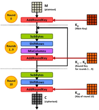
The AES-128 encrypts 128-bit plaintexts into 128-bit
ci-phertexts using a 128-bit key K. The algorithm performs 10 rounds (after a short initial round) and consists of two separated processes: a key schedule that derives round keys and the encryption routine itself. During decryption key sched-ule is reversed and encryption is replaced by a very similar decryption process.
The initial round uses K0 = K as a round key; for
all subsequent rounds, new round keys Ki are calculated
from their predecessors Ki−1. Figure 1 illustrates the AES’
structure.
In most implementations the Kis are computed and stored in
memory before encryption starts. Encryption treats the 16-byte plaintext M as a 4×4 byte matrix. Each round, except the first and the last, includes four steps: A substitution of the matrix’s contents using a lookup table (SubBytes), a rotation of the matrix’s rows (ShiftRows) and a linear transform in GF(28)
!""#$%&"'() !""#$%&"'() !""#$%&"'() *+,-$.%/&0 12+34#$50 12+34#$50 1%67)4(0 1%67)4(0 ! !"#$%&'()'* " !+%",(-'()'* # . !/$%&01(2* #3$$%#4 !567&801(20 96-0-67&8:030;;04* # 3. !1(20690-67&803.* !"#$% & !"#$%' ())* !"#$% (&
Fig. 1. TheAES- General Outline.
(MixColumns) combining each matrix element with other column elements weighted by different coefficients (1, 2 or 3). At the end of each round Ki is xored with MixColumns’s
result (an operation called AddRoundKey). III. LASERFAULTINJECTION
Laser (Light Amplification by Stimulated Emission of Ra-diation) is a stimulated-emission electromagnetic radiation in the visible or the invisible domain. Laser light is monochro-matic, unidirectional, coherent and artificial (i.e.laser does not spontaneously exist in nature). Laser light can be generated as a beam of very small diameter (a few µm). The beam can pass through various material obstacles before impacting a target during a very short duration.
Laser impacts on electronic circuits are known to alter func-tioning. In particular,SRAM(Static Random Access Memory) laser exposure is known to cause bit-flips [12], [6], [5], a phenomenon called Single Event Upset (SEU). By tuning the
!"#$%&'(&)
!"#$%&'(&)
!"#$%&'(&)
!"#$%&'(&)
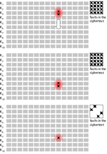
Fig. 2. Effects of one faulty round key byte at different rounds.
beam’s energy level below a destructive threshold, the target will not suffer any permanent damage. In a laser attack, the opponent usually controls the beam’s diameter, wavelength, amount of emitted energy, impact coordinates (attacked circuit part) and the exposure’s duration. Sometimes, the opponent may also control the impact’s moment1, the target’s clock
frequency, Vcc and temperature. Finally, laser attacks may
indifferently target the chip’s front side or back side. IV. PIRET-QUISQUATERDFA
Differential Fault Analysis [2] (DFA) is an analysis
tech-nique exploiting differences between correct and faulty out-puts. Several byte-level andbit-level AES DFA variants exist
(e.g.[8], [9], [7], [3]). Given the dependence of these attacks on precise “surgical” fault injection, the feasibility of bit/byte-level DFAremained somewhat unclear.
[11] describes a byte-level DFA on AES (the so-called
Piret-Quisquater’s DFA). This attack requires the injection
of a single-byte fault into the temporary ciphertext between the MixColumn exit of the antepenultimate round and the MixColumninput of the penultimate round to be successful. A means to meet this requirement is to inject a single-byte fault into the antepenultimate round key (namely K8). As
a consequence, a faulty ciphertext with four faulty bytes is obtained (see Figure 2). Then, the attack scheme described in [11] allows to infer some informations on the four cor-responding bytes of K10 by processing the correct and faulty
ciphertexts and checking over the list of all the related possible single-byte faults.
By repeating this process twice (i.e. by iterating the attack for a different plaintext) the exact value of the four bytes of K10 is found with a success rate of about 98% [11]. The
procedure is repeated to target K10’s remaining bytes. Finally,
K = K0 is inferred by reversing the key schedule. We show
that this attack can be implemented, even when the laser spot is wider than the SRAM’s cell.
V. PRACTICALSINGLE-BYTEFAULTINJECTION
Outline: After chip decapsulation and a mapping of the chip’s components, we selected a large target area, given our
1i.e.the impact’s synchrony with a given clock cycle of the target.
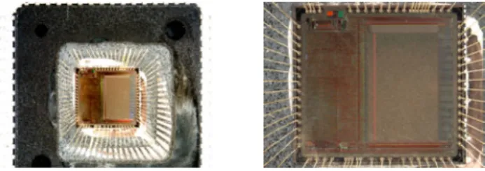
Fig. 3. Decapsulated chip (SRAMis on the left middle and bottom side).
knowledge of the implementation. Using automated search on the chip’s front-side, we modified the impact’s coordinates, the beam parameters and timing until a one byte fault was obtained. Finally, Piret-Quisquater’s attack was performed.
The target is an 8-bit 0.35 µm 16 MHzRISCmicrocontroller
with an integrated 4KB SRAM and no countermeasures. The
device runs SOSSE (Simple Operating System for Smartcard Education [4]) to which we added some commands, most notably for feeding-in cleartexts and retrieving ciphertexts. K was embedded in the code. As encryption starts, the Kis are
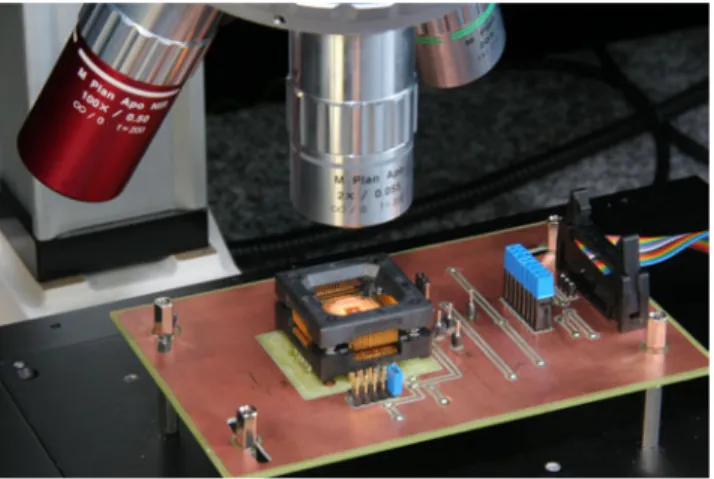
derived and stored in SRAM. The laser, shown in Figures 7
and 8, is equipped with a YAG laser emitter in three different
wavelengths: green, infrared and ultraviolet.
The spot’s diameter can be set between 0 and 2500µm. As the beam passes through a lens, it gets reduced by the lens’ zoom factor and loses a big part of its energy. Our experiments were conducted with a 20× Mitutoyo lens, a green2 beam of ∅4µm and ≃ 15pJ per shot. The circuit is
installed on a programmable Prior Scientific X-Y positioning table3. The X-Y table, card reader, laser and anFPGA trigger
board, were connected viaRS-232 to a controlPC. TheFPGA
trigger board receives an activation signal from the reader and sends a trigger signal to the laser after a delay defined by the control PC.
Experiments were conducted in ambient temperature and at Vcc = 5V. These parameters are within the device’s normal
operating conditions 2.7V ≤ Vcc≤ 5.5V .
The chip was decapsulated by chemical etching using a Nisene JetEtch automated acid decapsulator. The decapsulator can be programmed for the chemical opening of different chip types using different ratios of nitric acid (HNO3) and sulfuric
acid (H2SO4), at a desired temperature and during a specified
time. For opening our chip, we used only nitric acid at 80◦C
for 40 seconds. The etched chip (Figure 3) successfully passed functional tests before and during fault injection.
As it is very difficult to target the chip’s (ALU) (Arithmetic Logic Unit) and inject only a single-byte fault during a very specific instant between the end of MixColumn of the 8-th round and before 8-the MixColumn of 8-the 9-8-th round, we decided to target K8.
Finding the SRAMarea containing K8 and properly tuning
the laser’s parameters is very time consuming. The number of
2532nm wavelength.
Fig. 4. Decapsulated chip (closeup onSRAM).
!"#$%&' !"#$%&( !"#$%&) !"#$%&*+
,-"./- 011023 145/6&071/- #84$9 : 0$%&;/7"-/ #84$9 :
!"""
Fig. 5. Attack’s timing. TABLE I
POTENTIAL FAULTYKiS AS FUNCTION OF OBSERVED FAULTY
CIPHERTEXT BYTES.
number of faulty C bytes potential faulty round keys
K10 K9 K8 previous round keys
1, 2, 3 ! !
4, . . . , 15 ! ! !
16 ! ! ! !
faults in the ciphertext (C), their position and their contents indicate which round key has been hit. MixColumns will amplify any single-byte fault occurring in any Ki preceding
K8 and result in a completely faulty ciphertext (we call such
a bad event an “early fault”). As shown in Figure 2, a single-byte fault on K8 changes 4 ciphertext bytes while a fault in
K9 or K10 changes only one byte. However, injected faults
are not always limited to a single byte and/or to a single Ki.
When more than 4 ciphertext bytes are faulty, it is difficult to determine if the observed result is due to an early fault or to several faults in K8, K9 and K10 (Table I). After finding
sensitive SRAM areas that affect the ciphertext, and before targeting K8, we tried to find the memory cells containing
K10. This is necessary for tuning beam-size and energy to
limit the fault injection area to very few bytes and preferably one byte. Despite fine-grained energy and spatial control we detected faults in keys neighboring K8. To overcome this
problem, we isolated K9 and K10 from faults and restricted
the shot to a 100 µs interval between the use of K7 and K8
(Figure 5).
Figure 6 shows how we could confine faults to a single byte
! ! ! ! ! ! ! ! ! ! ! ! ! ! ! ! ! ! ! ! ! ! ! ! ! ! ! ! ! !
Fig. 6. Exploration process.
Fig. 7. Laser and target (general overview).
of K9. When more than one faulty byte existed, we could
obtain single byte faults by controlling the laser’s shooting time. Figure 6 is just a model of the real SRAM(Figure 4) to
describe our technique and does not correspond to real address allocation. We could successfully inject faults into 13 bytes of K8. This sufficed to run Piret & Quisquater attack.
As shown in the topmost part of Figure 6, we searched K8’s
precise storage area by monitoring the number and the type of faults in the ciphertext. Then (middle part of Figure 6), by a precise beam localization, we managed to inject faults only in K8. This, however, did not turn out to be fully deterministic
as sometimes we would also inflict faults to previous round keys. At that point (lowermost part of Figure 6), by fine-tuning spatial and temporal beam localization (just after the use of
Fig. 8. Laser and target (closeup).
K7), we managed to restrict the injected faults only to K8.
This is the exact assumption of Piret-Quisquater’s scenario. VI. CONCLUSION
We implemented Piret-Quisquater’s attack [11] using laser fault injection. [11] is usually regarded as the most effective fault attack on AES as it requires only two faulty ciphertexts. This effectiveness comes at the price of stringent fault injection assumptions. The experiments reported in this paper also apply to other attacks (e.g. [8], [9]) and underline the possibility
to preciselymodify flags, counters, pointers and other single
memory cells that control program flow, in the absence of countermeasures.
In summary, this note’s main conclusions are:
• It is possible to implement a single-byte laser fault attack
on an AES round key.
• Even when it is physically impossible to target a
single-byte because the beam hits a few other single-bytes, careful spatial and temporal coordination may allow to deceive the encryption process to consider logically only a single-byte fault that corresponds to Piret-Quisquater’s scheme.
• It is possible to reproduce the same faults on different
plaintexts. This assesses the reality of Piret-Quisquater’s scenario on unprotected chips.
As we send this paper to press we can already refer the reader to recent reproduciblesingle-bit fault injection results [1].
REFERENCES
[1] M. Agoyan, J.M. Dutertre, A.P. Mirbaha, D. Naccache, A.L. Ribotta and A. Tria,How to flip a bit?, International On-Line Testing Sympo-sium – Proceedings ofIOLTS2010,IEEE, 2010, In press.
[2] E. Biham and A. Shamir, Differential fault analysis of secret key cryptosystems, Proceedings of Crypto’97,LNCS, vol. 1294, Springer-Verlag, 1997, pp. 513–525.
[3] J. Bl¨omer and J.P. Seifert,Fault based cryptanalysis of the Advanced Encryption Standard (AES), Financial Cryptography – Proceedings of
FC2003,LNCS, vol. 2742, Springer-Verlag, 2003, pp. 162–181. [4] M. Brstle et al., SOSSE – Simple Operating System for Smartcard
Education, www.mbsks.franken.de/sosse/index.html.
[5] G. Canivet, Analyse des effets d’attaques par fautes et conception s´ecuris´ee sur plate-forme reconfigurable, Ph.D. thesis, Institut polytech-nique de Grenoble, 2009.
[6] F. Darracq, T. Beauchˆene, V. Pouget, H. Lapuyade, D. Lewis, P. Fouillat and A. Touboul,Single-event sensitivity of a single SRAM cell,IEEE
Transactions on Nuclear Science, vol. 49 (3), IEEE, 2002, pp. 1486–
1490.
[7] P. Dusart, G. Letourneux and O. Vivolo,Differential fault analysis on
A.E.S., Proceedings of the Int. Conf. on Applied Cryptography and
Network Security – ACNS 2003, LNCS, vol. 2846, Springer-Verlag, 2003, pp. 293–306.
[8] Ch. Giraud,DFAonAES, Proceedings ofAES2004,LNCS, vol. 3373,
Springer-Verlag, 2005, pp. 27–41.
[9] A. Moradi, M.T. Manzuri Shalmani and M. Salmasizadeh, A gen-eralized method of differential fault attack againstAEScryptosystem, Cryptographic Hardware and Embedded Systems – Proceedings of
CHES2006,LNCS, vol. 4249, Springer-Verlag, 2006, pp. 91–100. [10] National Institute of Standards and Technology (NIST),Announcing the
advanced encryption standard (AES), Federal Information Processing Standards Publication, vol. 197, 2001.
[11] G. Piret and J.J. Quisquater,A differential fault attack technique against SPN structure with application to theAESandKHAZAD, Cryptographic Hardware and Embedded Systems – Proceedings ofCHES2003,LNCS, vol. 2779, Springer-Verlag, 2003, pp. 77–88.
[12] S. P. Skorobogatov and R. J. Anderson,Optical fault induction attacks, Cryptographic Hardware and Embedded Systems – Proceedings of
CHES2002,LNCS, vol. 2523, Springer-Verlag, 2002, pp. 2–12.
[13] A. Tria, B. Robisson, J.M. Dutertre and A.P. Mirbaha, Fault at-tacks from theory to practise: what is possible to do?, 2-nd Canada-France Workshop on Foundations & Practice of Security, 2009. www-mitacs2009.imag.fr/Material/mitac part1.pdf and mitac part2. pdf