HAL Id: cea-02928022
https://hal-cea.archives-ouvertes.fr/cea-02928022
Submitted on 2 Sep 2020
HAL is a multi-disciplinary open access
archive for the deposit and dissemination of
sci-entific research documents, whether they are
pub-lished or not. The documents may come from
teaching and research institutions in France or
abroad, or from public or private research centers.
L’archive ouverte pluridisciplinaire HAL, est
destinée au dépôt et à la diffusion de documents
scientifiques de niveau recherche, publiés ou non,
émanant des établissements d’enseignement et de
recherche français ou étrangers, des laboratoires
publics ou privés.
Improvement of Nuclear Heating Evaluation inside the
Core of the OSIRIS Material Testing Reactor
Arthur Peron, Fadhel Malouch, Cheikh Diop
To cite this version:
Arthur Peron, Fadhel Malouch, Cheikh Diop. Improvement of Nuclear Heating Evaluation inside the
Core of the OSIRIS Material Testing Reactor. ISRD 2014 - 15th International Symposium on Reactor
Dosimetry, May 2014, Aix en provence, France. �cea-02928022�
of the OSIRIS Material Testing Reactor
Arthur Péron1a, Fadhel Malouch1, and Cheikh M. Diop1
1Alternative Energies and Atomic Energy Commission (CEA), Saclay center,
DEN/DANS/DM2S/SERMA, 91191 Gif-sur-Yvette Cedex, France
Abstract. In this paper we present a nuclear heating from neutron and photon rays
calculation scheme mainly based on the Monte-Carlo neutral particle transport code TRIPOLI-4® which takes into account fuel elements axial distributions of compositions. This calculation scheme is applied to the OSIRIS reactor in order to evaluate the effect of using realistic axially heterogeneous compositions instead of uniform ones. After a description of nuclear heating evaluation, the calculation scheme is described. Numerical simulations and related results are detailed and analysed to determine the impact of axially heterogeneous compositions on fluxes, power and nuclear heating.
1 Introduction
Technological neutron/photon irradiations undertaken in experimental reactors are essential for the safety for the current power reactor fleet as well as for testing innovative types of reactors. Irradiation programs carried out in Material Testing Reactors (MTR) must be representative of phenomena and irradiation conditions in actual power plants, in particular in terms of neutron flux (or fluence), pressure and temperature. Material samples irradiated inside a MTR core needs to have their irradiation conditions enslaved to fixed values. Temperature closed-loop control is obtained by electric heating elements or by modifying the nature of a gas surrounding the sample. This corresponds for about 20 % of the total temperature in irradiation samples. The other 80 % comes from the nuclear heating due to the energy deposited by neutrons and photons in samples. Nuclear heating varies approximately from 2 to 16 W/g and depends mainly on the sample nature. A reliable evaluation of such heating is also one of the key data for thermal studies in the design and safety of experimental devices.
The purpose of this paper is to highlight the effects of using an axial profile of compositions instead of a uniform composition for fuel elements in nuclear heating calculations using the Monte-Carlo neutron and photon transport code TRIPOLI-4. In this paper, the nuclear heating evaluation is first described and then the nuclear heating calculation scheme is detailed. Afterwards, the OSIRIS MTR and its modelizations for the TRIPOLI-4 code are presented. Then the effect of composition axial profiles on fluxes, power and nuclear heating are investigated and analysed. Finally, a comparison of results versus measurements is done.
15th ISRD
2 Nuclear heating evaluation using the TRIPOLI-4
®code
2.1 Deposited energy calculation
We recall here the basic definitions and properties of deposited energy KERMAs induced by a neutron flux in a coupled neutron-photon transport [1]. Nuclear heating due to neutrons can be conveniently expressed in terms of the KERMA factors , i.e., Kinetic Energy Release in Matter
where E is the incident particle energy. The definition of the kermas is such that the heating
rate of a mixture of different materials in a given volume reads at incident energy : ∑ ∑
Here is the atom density of material i, is the neutron (scalar) flux at E and is the
kerma factor for element i and reaction j at E. Thus, the kermas play the role of a microscopic reaction cross section, carrying units of [energy × cross section], i.e., [MeV × b]. In other words, the kerma factor expresses the total kinetic energy release ̅ induced by the reaction j in the
element i, at a given incident energy E, times the microscopic cross section for the same
nuclear reaction in the same material:
∑ ̅
where the sum is performed over all charged products resulting from the nuclear reaction j, including
the recoil nucleus. By definition, the term ̅ expresses the kinetic energy carried away by the cth
charged reaction product. The cross sections act as weight factors, in that they express the probability that each of the possible reactions contributes to the total energy release.
For most isotopes or natural elements in nuclear data libraries, however, detailed information for ̅ is not available, so that the kerma factors must actually be computed via the energy balance
method. This amounts to noting that the energy allocated to charged reaction products and recoil
nuclei is obtained by subtracting the energy carried away by transported neutrons and photons from the available initial (mass and kinetic) energy. It is crucial to recall that both neutrons and photons are assumed to be transported. The available energy for the reaction is given by the sum , where
is the reaction Q-value resulting from the mass defect (in energy units), measured with respect to the ground state of each nucleus. We have then:
∑ ̅ ̅ ̅
so that we obtain the neutron KERMAs:
[ ̅ ̅ ]
where ̅ is the mean energy carried away by the emitted neutrons (if any) and ̅ is the
mean energy carried away by the emitted photons (if any). In both ̅ and ̅ terms,
multiplicity is also taken into account. Equation 4 provides the energy balance method that is currently used in TRIPOLI-4 to compute the energy deposition [1].
According to the ENDF format [2], for all reactions j on the element i, the required cross sections
can be retrieved from nuclear data libraries in section MF3, and are associated to a distinct MT
number. Each MT number identifies a reaction with specific incoming particle, reaction products and residual nucleus (depending on the target nucleus i). The Q-value is coded in the header of each
MT reaction in MF3, but TRIPOLI-4 computes by resorting to mass defect calculations whenever
possible.
Energy deposition calculation is strongly correlated to nuclear data evaluations. A number of isotopes of the most common data libraries, such as for instance JEFF-3.1.1, JEFF-3.2 and
ENDF/B-VII.1 [3], are affected by energy and/or momentum conservation faults in the photon productions, which potentially result in negative kermas (typically when the photon energy exceeds the limit allowed by kinematics), sharp glitches (missing photons demanded by energy conservation), or inaccurate thresholds for photon emission sections [4] [5]. Such inconsistencies can be detected for instance by resorting to the kinematic limit method [6].
2.2 Coupled neutron-photon 3D calculation scheme
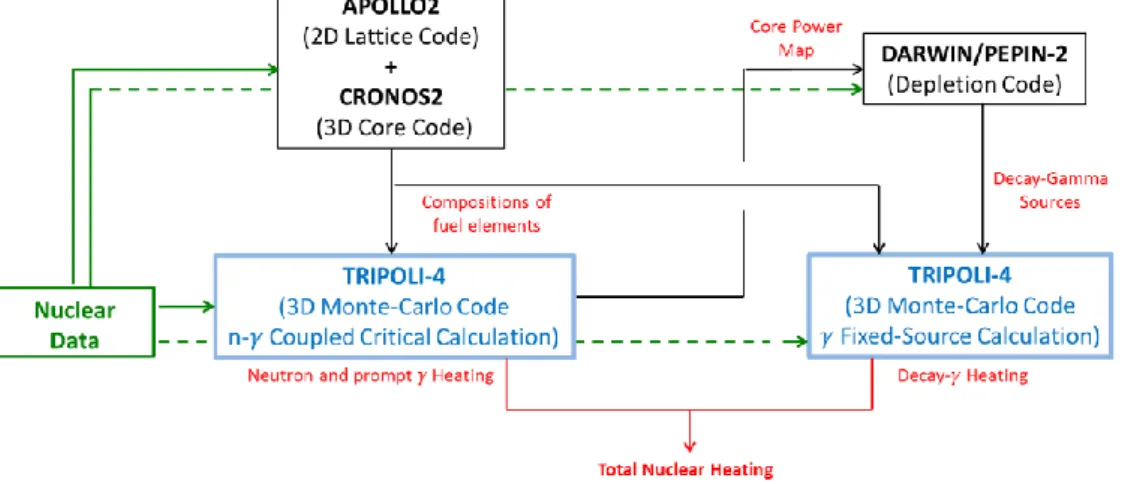
To evaluate nuclear heating in reactors, a three-dimensional coupled neutron-photon calculation scheme has been set up. The calculation scheme architecture is presented in Figure 1. It is based mainly on the TRIPOLI-4 Monte Carlo transport code which has been extensively validated against experimental results from neutron flux measurements performed in ex-core and in-core experiments [7][8]. Two TRIPOLI-4 simulations are needed to estimate the total nuclear heating. The first one is a coupled neutron-photon critical calculation for the nuclear heating due to neutrons and prompt photons. The second one is a photon fixed source calculation which simulates gamma from fission products decays. These two main steps need upcoming data: nuclear data which represent the physics of simulations and irradiation data for setting up geometry and compositions of the core. The calculation scheme uses nuclear data from the CEAV5_1.1 library, based mainly on the nuclear data library JEFF3.1.1 [9]. Irradiation data are either given by the user (control elements positions, loading of experimental devices…) or either computed by some deterministic calculation codes.
Figure 1. Nuclear heating evaluation scheme architecture
Until now, evaluations of compositions were done by a 2D core code coupled at the APOLLO2 lattice code thus nuclear heating calculations were necessary done with a uniform composition along the Z axis [10]. The purpose of this paper is to highlight the interest of realistic 3D irradiation conditions to estimate particle fluxes, power and nuclear heating for neutrons, prompt photons and decay photons. Estimations of fuel elements compositions are now performed with the APOLLO2 2D lattice code and the CRONOS2 3D core code. The APOLLO2 code calculates multi-group self-shielded cross sections on a fine energy grid (281 groups) for the different elements in the core. Cross sections are after condensed and stocked in libraries called SAPHYBs to be used by the CRONOS2 code. CRONOS2 allows the following of fuel elements evolution along their different irradiations by chained calculations. It permits to estimate axial distributions of burn-up and compositions for each fuel elements at a chosen time. This is a major innovation for nuclear heating evaluation in the case of the OSIRIS reactor.
3 Relevance of axial distributions of compositions for fuel element,
15th ISRD
3.1 TRIPOLI-4 modelization of the OSIRIS reactor
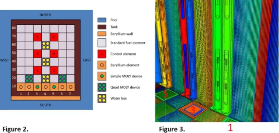
The OSIRIS Material Testing Reactor (MTR) is an experimental pool type light water reactor operational since 1966 at the CEA Saclay center. The core is a compact unit of 60 cm x 70 cm x 70 cm for a power of 70 MW. The core vessel contains a rack of 56 cells loaded with 38 standard fuel elements made of 22 fuel plates, 6 control elements (hafnium absorber above a fuel element) and up to 7 beryllium elements (Fig. 2). Two cells (22 and 26) are employed for the radioisotope production with medical use (MOLY devices). Cells 24, 44 and 64 are loaded with water boxes dedicated to experiments (up to four experiments rigs by water box).
The modelization of the OSIRIS core is as close to the plans as possible (Fig. 3), for example each fuel plate is taken into account, control elements can be moved or axial discretization of fuel element compositions can be modified.
Figure 2. Radial cross-section of the OSIRIS core (a number is associated at each position given by the sum of
the column and the line numbers. For example here we have 3 water boxes in positions 24, 44 and 64)
Figure 3. 3D modelization of the OSIRIS core for TRIPOLI-4 (red number refer to control element positions
from Figure 1.)
This part will show comparisons between three modelizations: a calculation with an axially uniform composition for fuel elements and two calculations with a fuel composition axial discretization of 7 and 21 cells. Comparisons are done for all core elements on an axial grid of 21 meshes containing the effective geometry. In the following we present results for two fuel elements and one irradiation element (water box) representative of phenomena. Fuel elements are in cells 34 and 84 (Fig.2) with respectively a mean burn-up of 80 and 15 GW.j/t and the water box is in cell 44. In this study we have evaluated the following quantities:
- neutron fluxes, prompt and decay photon fluxes, powers (obtained with fission reaction rates), neutron nuclear heating and prompt and decay photon nuclear heating for each fuel element on an axial mesh of 21 cells
- fluxes and nuclear heating for neutron, prompt photon and decay photon in the water box. In the study, Monte Carlo standard deviations are for all calculated tallies inferior to 1%.
3.2 Neutron and photon fluxes comparisons in fuel elements
Figure 4 shows that using axial distributions instead of an axially uniform composition altered the neutron flux axial profile. This phenomenon mainly depends on fuel element burn-up and increases with it. It is explain by an increase of neutron poison production and a loss of fissile elements in the middle of fuel elements during their life due to a more important neutron flux at this location. So, for a
high burn-up fuel element, neutron poisons are in more important concentrations at the centre while fissile elements are in reduced quantities. We can notice that 7 and 21 compositions cells gives similar results in term of neutron flux profiles and this is similar for prompt photons and decay photons.
Figure 4. Neutron axial distribution flux (integrated from 0 to 20 MeV) by axial mesh for 2 fuel elements at different burn-up ( a) 80 GW.j/t, b) 15 GW.j/t )
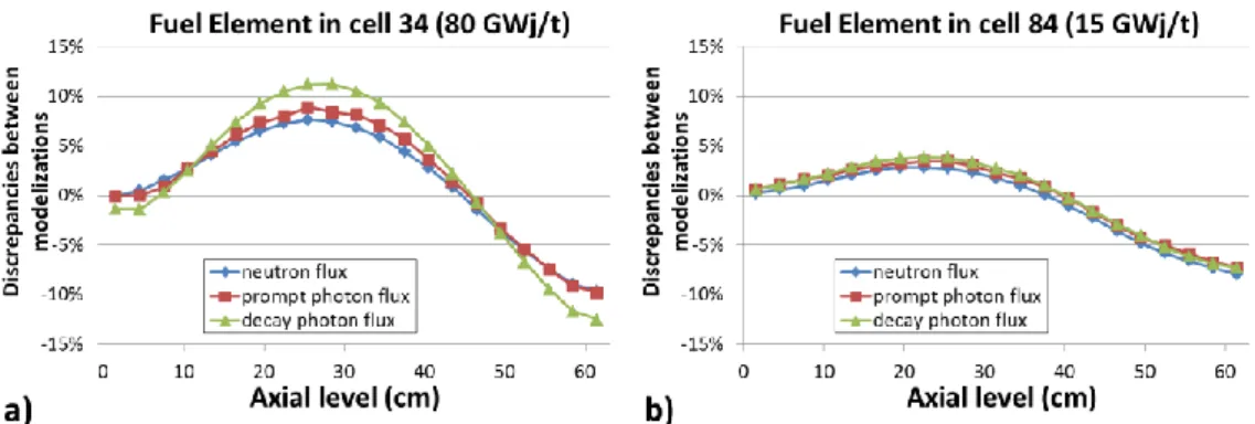
Figure 5. Flux discrepancies between 1 versus 21 cells modelizations for 2 fuel elements at different burn-up ( a) 80 GW.j/t, b) 15 GW.j/t )
Figure 5 quantify flux discrepancies between uniform axial compositions versus axial profile of 21 compositions. It highlights that fuel elements with high burn-up have their different fluxes (neutron, prompt photon and decay photon) affected by the axial distribution of compositions, but not in same term. Decay photon flux is the more affected (discrepancies from -12% to 12%) due to the important changes in term of fission products concentrations. Discrepancies on neutron and photon fluxes are similar (from -10% to 8%) because prompt photons are mainly created by neutron reactions.
3.3 Power and deposited energy comparisons in fuel elements
In fuel elements, powers and deposited energies are more affected than fluxes by a change in the axial distribution of compositions. First, there are more discrepancies between 7 and 21 axial compositions in term of power as shown in Figure 6. Secondly, with an axial distribution of concentrations, the axial power profile shape is more degraded and loses his symmetry. It corresponds more at expected results for the core geometry. Indeed, control elements in the upper part of the core reduce fissile elements loss by fission while irradiation. Thus, upper part of fuel elements at high
15th ISRD
burn-up gives more power than lower part. Discrepancies between 1 versus 21 compositions modelizations are in range of -18% to 17%.
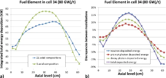
Figure 6. a) Power by cell for the 3 different modelizations b) discrepancies between power of the different modelizations
Figure 7. a) Total nuclear heating axial profile for 2 modelizations b) Discrepancies for the different nuclear
heating contributions (1_cell/21_cells – 1)
Nuclear heating and power are strongly correlated in fuel elements. Indeed, the major part of deposited energy comes from fission products which carried about 170 MeV from the 200 MeV Q-value. In that, power is close to neutron nuclear heating which represent about 95% of total nuclear heating. Thus, total nuclear heating axial profile (Fig. 7 b) ) in fuel elements is similar as the profile power. Concerning photon nuclear heating, prompt photons discrepancies they vary from -10% to 9% while decay photons discrepancies are in range of -14% to 12%.
3.4 Fluxes and deposited energy comparisons in water box
Results in experimental positions are less affected by axial compositions than fuel elements. Discrepancies are in range of -10% to 7% as shown in Figure 8. They correspond to the core average
discrepancies. These results are comparisons between calculations and need to be confronted to experiment. This has been done in the next part.
Figure 8. Discrepancies between 1 axial composition versus 21 compositions in water box in cell 44 a) fluxes b) deposited energies
4 Experimental validation using differential calorimetry
To complete this study we have setup a comparison of the three modelizations versus differential calorimetry results performed with the CALMOS experimental device [11] [12]. The principle of differential calorimetry is to compare the temperatures of a cell filled with a sample (of a given material) to a reference cell (with no sample). The temperature difference is directly correlated to the nuclear heating in the sample.In OSIRIS calorimeter devices, nuclear heating is measured in graphite samples because of its low atomic number which disturb not much the photon flux and its good transparency to neutron. Figure 8 shows results of measurements versus calculation results. We can see that using an axial profile for compositions changes the shape of nuclear heating in calorimeter, highly reducing discrepancies with measurements for positions above 5 cm high (from-76% to -39% at 43 cm). However, discrepancy at core mid-plane is lightly increase from -14% to -16.5%.
Figure 9. Comparison between experimental measurements and calculation results in position 44SO of the
OSIRIS core
5 Conclusions and prospects
In this paper we present a nuclear heating calculation scheme which takes into account fuel elements axial distributions of compositions. We apply the calculation scheme to the OSIRIS reactor and evaluate the effect of using realistic axially heterogeneous compositions instead uniform ones by
15th ISRD
calculation/calculation comparisons. Impacts are evaluated in fuel and experimental elements on fluxes, power or nuclear heating. This permits to highlight the importance of realistic compositions to take into account the good axial profile of calculated quantities which can be misevaluated by ±20%. However, this is a local phenomenon which mainly depends on fuel element burn-ups and poison productions and whole core is affected in lower proportion (-12% to 7%).
An experimental validation has been set up to complete this study. Results are compared to nuclear heating measurements performed using differential calorimetry in an experimental location. Discrepancies between measurements and calculation results are in range of -15% at core mid-plane and they are strongly reduced with the use of realistic compositions for the upper part of the core (from -76% to -39%).
Sources of discrepancies between experiments and simulations could be explained by a lack in photon production nuclear data [6] and simplifications concerning modelizations. Further investigations are ongoing to understand these discrepancies.
References
1. A. Zoia et al., Energy deposition in TRIPOLI-4, version 8, Rapport CEA 11-5165 A (2011). 2. National Nuclear Data Center, Brookhaven National Laboratory. ENDF-6 Formats Manual. Data
Formats and Procedures for the Evaluated Nuclear Data File ENDF/B-VI and ENDF/B-VII. CSEWG Document ENDF-102, Report BNL-90365-2009.
3. M.B. Chadwick et al., ENDF/B-VII.1 Nuclear Data for Science and Technology: Cross Sections, Covariances, Fission Product Yields and Decay Data, LA-UR 11-05121, LANL, USA, 2011. 4. http://t2.lanl.gov/nis/data/endf/ebalVII.1/summary.html
5. N. J. Peters, J. C. McKibben, K. Kutikkad, and W. H. Miller, Refining the Accuracy of Predicting Physics Parameters at Research Reactors due to the Limitations in the Energy Balance Method Using MCNP and the ENDF Evaluations, Nuclear Science And Engineering: 171, 210–219 (2012)
6. A. Péron, F. Malouch, A. Zoia, C. M. Diop, “Impact Estimation of Nuclear Data Inconsistencies on Energy Deposition Calculations in Coupled Neutron-Photon Monte-Carlo Simulation, with TRIPOLI-4®”, Joint International Conference on Supercomputing in Nuclear Applications and Monte Carlo 2013 (SNA+MC 2013), Paris, France, October 27-31, 2013
7. H. Carcreff, A. Alberman, L. Barbot, F. Rozenblum, D. Beretz and Y. K. Lee, “Dosimetry Requirements for Pressure Vessel Steels Toughness Curve in the Ductile to Brittle Range”, J. of ASTM International (JAI), Vol. 3, Issue 3, (Mar., 2006).
8. Y.K. Lee and F. Malouch, “Analysis of OSIRIS In-Core Surveillance Dosimetry for GONDOLE Steel Irradiation Pragram by Using TRIPOLI-4 Monte Carlo Code”, 13th International
Symposium on Reactor Dosimetry (ISRD13), Akersloot, Netherlands, May 21-25, 2008.
9. Santamarina A., Bernard D., Blaise P., Coste M., Courcelle A., Huynh T.D., Jouanne C., Leconte P., Litaize O., Mengelle S., Noguère G., Ruggieri J.M., Sérot O., Tommasi J., Vaglio-Gaudard C., Vidal J-F., “The JEFF-3.1.1 Nuclear Data Library, JEFF Report 22, Validation Results from JEF-2.2 to JEFF-3.1.1,” NEA No. 6807, OECD/NEA Edition 2009.
10. F. Malouch, “Development and Experimental Validation of a Calculation Scheme for Nuclear Heating Evaluation in the Core of the OSIRIS Material Testing Reactor”, Journal of ASTM International (JAI), Volume 9, Issue 4 (April 2012)
11. H. Carcreff, “CALMOS: Innovative Device for the Measurement of Nuclear Heating in Material Testing Reactors”, in Journal of ASTM International (JAI), Volume 9, Issue 3 (March 2012) 12. H.Carcreff, L.Salmon, C. Courtaux, “First In-Core Measurement Results Obtained with the
Innovative Mobile Calorimeter CALMOS inside Osiris Material Testing Reactor”, Advancements in Nuclear Instrumentation Measurement Methods and their Applications (ANIMMA-2013), 23-27 June 2013, Marseille.

![[PDF] Couche réseau formation gratuit](data:image/gif;base64,R0lGODlhAQABAIAAAP///wAAACH5BAEAAAAALAAAAAABAAEAAAICRAEAOw==)