HAL Id: cea-02500815
https://hal-cea.archives-ouvertes.fr/cea-02500815
Submitted on 6 Mar 2020HAL is a multi-disciplinary open access archive for the deposit and dissemination of sci-entific research documents, whether they are pub-lished or not. The documents may come from teaching and research institutions in France or abroad, or from public or private research centers.
L’archive ouverte pluridisciplinaire HAL, est destinée au dépôt et à la diffusion de documents scientifiques de niveau recherche, publiés ou non, émanant des établissements d’enseignement et de recherche français ou étrangers, des laboratoires publics ou privés.
Overview of the TrioCFD code: Main features, VetV
procedures and typical applications to nuclear
engineering
P.-E. Angeli, U. Bieder, G. Fauchet
To cite this version:
P.-E. Angeli, U. Bieder, G. Fauchet. Overview of the TrioCFD code: Main features, VetV procedures and typical applications to nuclear engineering. NURETH 16 - 16th International Topical Meeting on Nuclear Reactor Thermalhydraulics, Aug 2015, Chicago, United States. �cea-02500815�
OVERVIEW OF THE TRIOCFD CODE: MAIN FEATURES, V&V
PROCEDURES AND TYPICAL APPLICATIONS TO NUCLEAR
ENGINEERING
Pierre-Emmanuel ANGELI, Ulrich BIEDER, Gauthier FAUCHET
CEA-SACLAY, DEN/SAC/DANS/DM2S/STMF/LMSF, F-91191 Gif-sur-Yvette, France
[email protected]
ABSTRACT
The main objective of the present paper is to give an overview of the actual state of the TrioCFD project. TrioCFD is a software developed for about 20 years in the Nuclear Energy Division of CEA. The code is designed to treat efficiently various physical problems, such as turbulent flows, fluid/solid coupling, multiphase flows or flows in porous media. The domains of application are mainly related to the nuclear industry, in particular to the interaction of turbulent flow with the solid structures of nuclear reactors, that TrioCFD is able to handle successfully thanks to its massive parallelism. The TrioCFD project integrates a major procedure of Verification and Validation (V&V). Numerous verification tests are performed to avoid unintentional modifications and assure a proper implementation of the numerical methods, models and options. Non-regression tests are automatically launched and provide an evaluation of the differences between the development version and the latest released version. The validation is the other part of procedure. Its purpose is to carry out reference calculations on a large range of physical problems and compare their results to analytical, experimental or literature results. It leads to the definition of compromises between accuracy, robustness and restitution time and guarantees that the requirement of a correct quality of results is met. Some typical examples of recent qualification studies in nuclear domain are presented here. Most of them correspond to international experimental or industrial facilities and combine various complex physical phenomena.
KEYWORDS CFD, TrioCFD, Trio_U, V&V, qualification, nuclear engineering
1. INTRODUCTION
For several decades, the numerical simulation is being used increasingly in numerous domains, leading to the use of CFD codes as R&D tools. This usage is accompanied by a requirement of certification criteria, and verification that the later are met. The nuclear industry is a major consumer of numerical simulation, which supports for example the safety process and helps to the understanding of accidental situations. TrioCFD is a multiphysical code, supported by the Nuclear Energy Department of the French Atomic Agency (CEA) and mostly dedicated to scientific and industrial applications related to the nuclear industry [1][2]. TrioCFD (called Trio_U up to 2015) results from the uniting of three former codes, undertaken in the early 1990s, and developed for local and small-scale calculations using especially Reynolds-Averaged Navier-Stokes (RANS) and Large Eddy Simulation (LES) models. It embraces a variety of numerical methods, physical models and takes on massive parallel technology (HPC) to make the most of the growing power of supercomputers. More than 650 million cells and 1.3 billion degrees of freedom have been recently reached, and computed on 10,000 processor cores [3]. The Verification and Validation (V&V) is an integrant part of the TrioCFD project. The V&V is a major process providing an evaluation of the reliability level of the computed solutions, as well as the correct implementation of the
desired models [4][5][6]. Particular methodologies have been defined to handle the evolution of the simulation database along the code versions. The validation work naturally leads to user recommendations adapted to specific cases, in order to exploit at best the code capacities. The purpose of the present paper is to provide a general overview of the TrioCFD project, from the coding and numerical features to the associated V&V procedures. Some typical nuclear related applications are briefly described, with an emphasis given to single phase thermal hydraulic flows, though chemistry and multiphase flows with a front-tracking method are also major components of the code. Up to now, TrioCFD is a proprietary software of the CEA with an external use mostly based on collaborations, but the passage in open source has been decided and is effective in 2015 under the BSD license. The main objectives are to diversify the applications and enlarge the user community. For this occasion, the software name has been changed from Trio_U to TrioCFD.
2. OVERVIEW OF THE TRIOCFD CODE 2.1. Code architecture
The TrioCFD code runs on every kind of Linux 32/64 bits systems from PC to HPC, and is implemented in C++ with the use of macros instead of standard template libraries. The code has an object-oriented conception composed of 1500 classes. The class hierarchy can be visualized through UML (Unified Modeling Language) diagrams showed in a HTML documentation automatically updated. The original choice of C++ is fully justified by the performance, efficiency and C/Fortran compatibility of this programming language. TrioCFD is based on a kernel including mainly the equations, time schemes and mathematical solvers, representing 40% of the software. Around the kernel are linked several modules representing the space discretization methods or the physical models. The objects are class instances and range from problem type (e.g. turbulence) and equation (e.g. incompressible Navier-Stokes) to physical parameter (e.g. viscosity) and boundary conditions (e.g. non-slip wall), with a lot of lower level objects. The data encapsulation enables the user to manipulate objects without modifying them and provides an easy evolvability and maintainability. Co-development is made possible by the use of the open source Git or Mercurial revision control software. This configuration management handles the different versions and modifications introduced by the developers. The calculations are launched by means of data files containing instructions specified by the user for solving the numerical problem. TrioCFD is delivered with several documents, among which a user’s manual listing and describing the keywords available in the code [7], and a developer’s manual. Further details on the code architecture can be found in [8]. 2.2. Discretizations and numerical methods
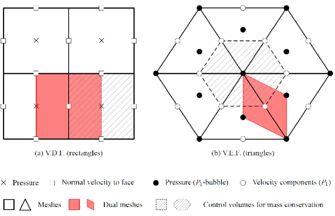
The fluid mechanics equations are solved through staggered finite-volume approaches. TrioCFD includes tools to generate robust meshes or to import meshes from other softwares. The code supports full parallelepiped or full tetrahedral meshes, whether they be structured or unstructured. Non-conform meshes and prismatic meshes are not accepted for now, but these options are under consideration. The spatial discretization methods corresponding to the different types of mesh elements are called finite volume differences (V.D.F.) for parallelepipeds and finite volume elements (V.E.F.) for tetrahedra [9][10][11][12]. These methods combine respectively the finite difference and the finite element methods with the finite volume method, gathering the advantages of each approach for incompressible Navier-Stokes problems. Velocity and temperature variables are located at the cell faces and the corresponding finite elements in V.E.F. are nonconforming P1. Pressure is at gravity center in V.D.F., and additionally at nodes (P1-bubble) in V.E.F. (in 3D pressure unknowns can be optionally added at edges in particular cases of thermal stratification or natural convection). The localization of unknowns for both kinds of discretization is summarized inTable I.
Table I. Localization of the unknown discretized fields. Localization in a cell
Variable V.D.F. V.E.F.
Velocity components Faces Faces
Pressure Center Vertices + center
Scalars (temperature, concentration, k, ε, …) Center Faces
Turbulent viscosity Center Center
A dual mesh is built in such a way that the degrees of freedom are located at the center of dual elements, as shown on Figure 1, and the equations are integrated over these new control volumes. Then the resolution in V.D.F. is based on finite difference approximations of fluxes, and the resolution in V.E.F. on a variational approximation of the equations using P1 basis functions. The resulting number of control volumes corresponds to the number of faces in the mesh, namely about twice the number of cells. Obviously for a same number of elements, the computational cost is much lower in V.D.F. than in V.E.F. discretization, due to less control volumes and a better conditioned pressure matrix.
Figure 1. Schematic 2D representation of discretization methods in TrioCFD with respective positioning of degrees of freedom and control volumes.
The staggered arrangement of velocity and pressure avoids the creation of spurious pressure modes (“checkerboard”) compared to a collocated arrangement [13]. Computations of velocity and pressure fields are decoupled using a projection method, where an intermediate velocity is computed and the mass conservation is then corrected by solving a Poisson equation for pressure on every control volume shown on Figure 1. The pressure matrix inversion is based on PETSc [14] solvers using either direct methods (Cholesky factorization) or on iterative methods (preconditioned conjugate gradient method with modifiable convergence threshold and SSOR preconditioner. TrioCFD handles numerous usual time
schemes and convection schemes of different orders. The time discretization can be done with explicit schemes (e.g. Euler, Runge-Kutta, Adams-Bashforth, Crank-Nicholson) or implicit schemes (e.g. Euler, Adams-Moulton, backward differentiation). A multiplicative factor of time step can be eventually applied to speed up a calculation towards the stationary state, provided that the stability is respected. Various convection schemes are usable including several possible flux limiters.
2.3. Turbulence models
Usual approaches to predict turbulent flows are considered, namely Direct Numerical Simulation, Reynolds-Averaged Navier-Stokes and Large-Eddy Simulation. At present TrioCFD DNS applications remain mostly dedicated to academic configurations [15]. The most common RANS models are integrated in TrioCFD. The fast and simple mixing length scheme [16] can be employed to obtain a first approximation for a various range of flows without boundary layer separation. Standard k-ε model [17] is used in numerous studies and classically compared to LES approaches [18][19]. The hydraulic and thermal turbulent models are coupled by the turbulent Prandtl number, denoted by Prt. In the Prandtl model, the turbulent kinematic viscosity and thermal diffusivity are linked by
t t t Pr
(1)
Though the turbulent Prandtl number is close to unity for most fluids, user defined values or functions can be assigned for Prt. It enables to improve the near-wall thermal prediction for liquid metal flows, which are of great importance in the nuclear field. For now, other RANS closures (e.g. Rij-ε, k-ω) are not included in TrioCFD. However a reflection has been recently engaged about the implementation of these approaches to overcome the limits of standard k-ε validity (e.g. flows with obstacles). Low Reynolds approaches are in the process of validation in 2015. LES are a major part of the TrioCFD studies. In recent years, the LES modeling is not being applied only to meteorological field [20] but is getting more and more usual for industrial applications because it gives access to temporal flow fluctuations. Many subgrid-scale models with various options are available. The WALE model (Wall-Adapting Local Eddy-viscosity [21]) is the most commonly employed by TrioCFD users, in order to correctly calculate near-wall flows in combination with near-wall functions. Nevertheless the Smagorinsky closure is useful if WALE model fails to properly dissipate the high frequency fluctuations. Noisy inlet boundary conditions, or inlet turbulent profiles computed from preliminary periodic box calculations, can be applied in the code to generate turbulence in case of pipe flows.
In complex industrial applications, the near-wall mesh refinement is a limiting factor for the accuracy of predictions, due to the resulting increase of the computational time. To overcome this difficulty, wall laws are usually employed to combine insufficiently low parietal y+ values and a proper connection to the off-wall turbulent flow. Several robust methods with numerous options are available in TrioCFD to enforce the wall laws. The hydraulic and thermal formulae implemented in the code are respectively the universal Reichardt [22] and Kader [23] laws. They can be conjugated with both RANS and LES models.
2.4. Post-processing
As for any CFD code, TrioCFD offers various solutions for the post-processing of the results. A numerical data base is constituted by periodically writing output results files during a run. They contain useful data for the analyses and comprehension of physical phenomena (e.g. fluxes, constraints). Probes files gather values of chosen fields at user specified localizations and provide the corresponding profiles along lines or circular arcs. Visualizations files can be transferred onto graphical interfaces showing flow images at given instants according to particular fields. Especially for large meshes, the results can be stored in binary format to avoid memory overload and speed up their exploitation. For unsteady flows like
LES, TrioCFD can provide statistics by computing and exporting the time averaged and standard deviation values of chosen fields as the simulations come along. The code also includes a tool allowing to check energy spectra by Fourier transformations.
2.5. Massive parallelism and code performance
One of the limiting factors for CFD simulations with very large meshes is the power and availability of computer resources for an acceptable resolution time. Data structures and functions of TrioCFD allow a simulation to be quickly parallelized and take advantage of the highest number of processor cores. Transfer and communication between cores use the MPI protocol (Message Passing Interface). Parallel input-output procedures optimize the data exchange between code and hard disc. Massive parallel calculations with TrioCFD can be carried out onto supercomputers. The CEA benefits from the Very Large Computing Centre (TGCC), dedicated to High Performance Computing (HPC) and opened to European scientists. Curie and Airain are the TGCC clusters respectively distributed over 92,000 and 20,000 cores designed by Bull, and with respective aggregate peak performance of 2 petaflops and 420 teraflops. Curie is the French component of PRACE Research Infrastructure [24].
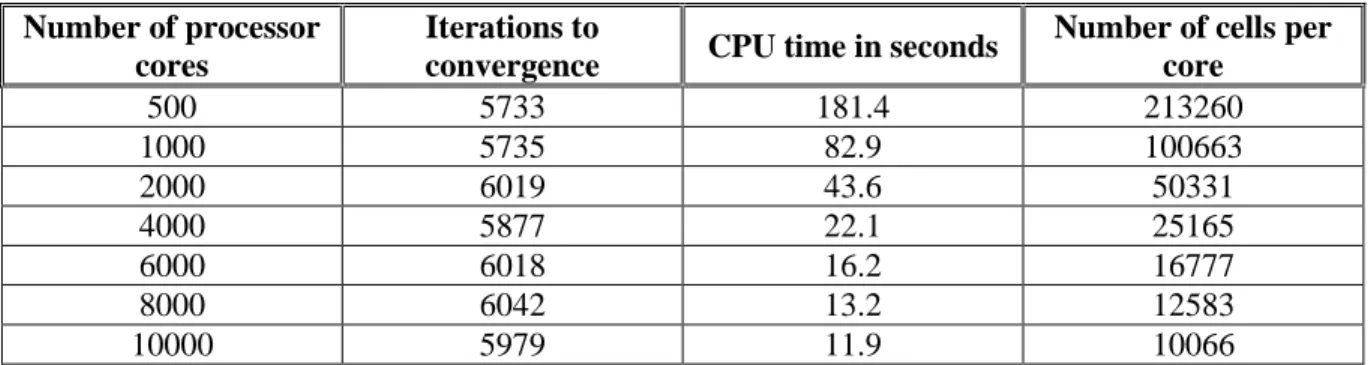
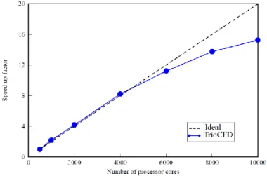
The efficiency of parallelism using TrioCFD has been evaluated by a strong scaling test as part of a numerical study of a nuclear assembly with mixing grids [3]. The physical problem considered in the tests is the balancing of a temperature gradient by pressure in a cube. The domain is meshed with 128x128x128 cubic cells divided into 100 million tetrahedral cells (200 million control volumes for the velocity); the calculations are made using the V.E.F. method. The pressure matrix is a sparse matrix due to the P1 nature of finite elements, of order 118 million, i.e. pressure points. The matrix is inverted by means of the PETSc conjugated gradient algorithm with SSOR preconditioning. Table II summarizes the parallel performance of the solution method after decomposition of the whole domain using METIS [25] on 500 to 10,000 processor cores. The speed up coefficient is given in Figure 2 for the first time step. The ideal speed up is maintained up to about 5,000 cores and about 20,000 tetrahedral cells or 23,600 pressure points per core, respectively. Fewer elements per core increase significantly the communication between the processor cores, which leads to a substantial reduction in the parallel performance. It must be noted that the pressure resolution cost corresponds to 60% to 80% of one time iteration cost.
Table II. Result of strong scaling for the first time step. Number of processor
cores
Iterations to
convergence CPU time in seconds
Number of cells per core 500 5733 181.4 213260 1000 5735 82.9 100663 2000 6019 43.6 50331 4000 5877 22.1 25165 6000 6018 16.2 16777 8000 6042 13.2 12583 10000 5979 11.9 10066
Scalability study in more industrial configurations is very tricky to perform. In the framework of a PRACE proposal, scalability in V.D.F. was shown to be slightly better than in V.E.F.. However it should be pointed out that V.D.F. is hard to apply for complex geometries due to the Cartesian mesh imposed by the method.
Figure 2. Measured speed up factor in V.E.F. when increasing the number of processor cores. 3. V&V SCHEMES AND PROCESS
3.1. V&V needs in CFD
V&V procedures have been first defined by the Society for Computer Simulation [26], according to Figure 3. Their introduction in the field of CFD and calculation codes arises from the need to demonstrate that the desired physical models and numerical methods are correctly implemented (Verification), and that codes provide accurate results according to reference data (Validation). Code verification is not related to physics but checks out that the code solves the physical model that is supposed to be implemented, by means of the expected numerical methods. Code validation consists in performing simulations by reproducing as closely as possible flow configurations for which external data (experimental, theoretical or from other codes) are available. In the TrioCFD project, V&V procedures are performed for testing the code behavior on a large panel of test cases, and are repeated whenever the code is subsequently modified or enhanced. They have been set up since the beginning of the software development and are permanently enriched with new test cases. A significant effort has been recently engaged to reorganize the validation database along with the passage of TrioCFD in open source in 2015. The test cases are classified into non-regression tests, validation files and reference calculations. A third part included in assessment of CFD is the demonstration step, i.e. the ability for a code to handle specific physical applications [28].
The next two subsections of the paper deal with the verification step and the validation step, respectively. The last section presents some demonstration cases related to several industrial applications.
3.2. Methodology for verification in TrioCFD
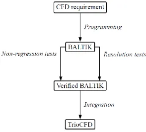
The verification consists mainly in minimizing source code programming errors during the development of computerized models. This step involves mainly the code developers. New developments corresponding to specific CFD requirements are first programmed in a separate environment named BALTIK (Building Application Linked with TrioCFD Kernel). One needs to demonstrate the stability, consistency, and robustness of what has been coded. This is done in two stages. First the influence of the BALTIK on the other parts of the code is estimated by subjecting it to a collection of non-regression test cases. These calculations are performed over only several time steps, and the relative difference between the new solutions with the former ones is evaluated. If the difference overtakes a specified threshold in one test or more, the new development is temporarily rejected until it passes all the non-regression tests. This procedure prevents from accidentally introducing bugs and unwanted modifications in the code, and assures the durability of the quality results as the code progresses. About 400 non-regression tests are run every night. The number of non-regression test cases is large because every model, scheme and option is verified. The new functionalities added in TrioCFD are likely to extend gradually the database of non-regression tests. This first step is carried out automatically by means of a scripted process. The second step of the BALTIK verification relies on the result analyses of complete test calculations. This step is performed by the developer, eventually assisted by other users. Unlike the non-regression cases, the tests are specific to the BALTIK to be verified, namely only the new parameters (models, schemes, options …) are activated. They demonstrate that the modifications are correctly taken into account and the equations correctly solved, for example by comparing the calculated solutions to available analytical solutions or highly accurate and reliable numerical solutions.
Once the verification procedure is achieved, the BALTIK is definitely integrated and available in the following release of the software. The different stages of the verification methodology are shown on
Figure 4
.Figure 4.
Overview of the verification procedure in TrioCFD. 3.3. Methodology for validation in TrioCFDThe validation process puts the stress on the physical compliance of the predictions given by a CFD tool with the real flows under consideration. The validation procedure in TrioCFD relies on two distinct databases, the database of validation files and the database of reference calculations. The validation
databases contain test cases covering a large range of physical problems, representative of usual phenomena related to fluid flows. Examples are given in Table III.
Table III. Overview of database tests for TrioCFD validation.
Physical issue Examples
Laminar flow Poiseuille flow, flow past obstacle, porous media Turbulent flow Mixing length, RANS, LES, jet flow
Natural/mixed convection Conjugate heat transfer, thermal stratification, heated floor
To each case is associated a pack of reference external available data coming from literature, exact solution (if possible) or other calculation codes, useful for comparison. The objective of validation files is to estimate the agreement between the computational results with several varying parameters or meshes. Experimental uncertainties (random and bias errors, fluid and scale effects), but also computational uncertainties due to missing initial conditions, boundary conditions, or modeling parameters are as far as possible considered. A script launches automatically the test cases scheduled in each validation file, extracts the pertinent post-processing data, and produces a report file summarizing the results and allowing to conclude about the model validation. Unlike the non-regression tests, the simulations are continued until convergence is reached. The validation files are the main way to generate best practice guidelines which can be referred to, especially for minimizing errors related to input data files or convergence (due to temporal/spatial discretization or iterative procedure). The particular TrioCFD specifications are added to the usual CFD recommendations. Some options can sometimes be excluded from certain flow simulations because of non-physical or numerically inadequate behavior in these specific cases. These procedures make convenient for a developer to test the effect of a new model on some relevant calculations, and for a user to test the effect of given functionalities before using them in complex studies. The TrioCFD reference calculations embrace a variety of global studies that can constitute entry points for more complex or full industrial problems. The associated data files are regularly tested to ensure that they meet the required syntax, which is likely to change during the code development. As a consequence, running former validation tests is always successful unless the models are deliberately modified. The user manual is updated at each version delivery.
4. TYPICAL APPLICATIONS AND QUALIFICATION STUDIES 4.1. Overview of industrial themes
The use of TrioCFD is relevant to investigate a wide range of industrial flows at different scales, combining various complex physical phenomena, from flows in pressurized water reactors, sodium fast reactors and sub-assembly bundles, to containment flows and atmospheric dispersion. Some demonstration examples are given in Table IV for recent typical nuclear applications. Most of these tests correspond to international experimental facilities.
Table IV. Typical TrioCFD studies related to industrial issues.
Industrial theme Qualification studies
Pressurized Water Reactors LACYDON, ROCOM, UPTF
Sodium Fast Reactors CORMORAN, MONJU
Jet mixing, thermal striping HYPI, WATLON, NAJECO, WAJECO, PLAJEST Sub-assembly bundles AGATE, ESTHAIR, PLANDLT, GR16
Atmospheric dispersion BUGEY
Several of these applications are briefly described below. 4.2. Boron mixing
The transport of un-borated water into the core region can lead to local power excursion and core damage (criticality accident). ROCOM experiments of HZDR (Konvoi type reactor) [27] and LACYDON experiments of CEA (French 900 MWe PWR) were used to validate the code on reduced scale (1:5), and UPTF Tram experiments were used to validate on reactor scale, as shown in
Figure 5
. The possible return to criticality has been analyzed for a French 900 MWe reactor [1].Figure 5. Boron concentration during the transient: downcomer on the left and core inlet on the right (TrioCFD calculation).
4.3. Main steam-line break rupture (MSLB)
The break of a main steam-line leads to a significant cooling of the flow in the affected loop. Transporting the colder water into the core region can lead to power excursion and core damage. LACYDON experiments of CEA (French 900 MWe PWR) and a commissioning experiment of the VVER1000 reactor at Kuzloduy [29] were used for validation; the temperature field in a French 900 MWe reactor has been analyzed without coupling to neutronics.
4.4. Induced break severe accident
In the case of a severe accident, overheated steam is transported via the hot leg to the steam generator where it impacts on the steam generator tube support plate and partly enters into the tubes. Simulations of the single phase gaseous flow in the hot leg and the steam generator have been performed to support mechanical calculations in order to predict the most probable location of the possible break [30].
4.5. Mixing grid analysis for PWR
Mixing grids in fuel assemblies are developed and optimized by the vendors to increase the turbulence level and vertical exchanges in an assembly; the associated pressure loss is minimized at the same time. In this context, the code was validated against AGATE experiments of CEA [19] and MATHIS_H experiments of KAERI.
4.6. Hydrogen risk
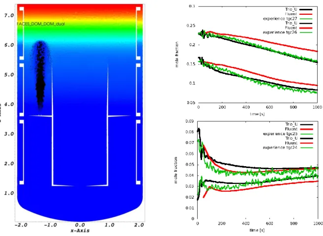
After Fukushima accident, the investigation of the formation and destruction of stratified hydrogen layers in containment got more and more important. TrioCFD has been validated against MISTRA and PANDA experiments [31], as illustrated in Figure 6.
Figure 6. Hydrogen erosion in the MISTRA facility: top at high location, bottom at low location (TrioCFD calculation).
4.7. Fuel assemblies for SFR
SFR fuel assemblies are characterized by the presence of spacer wires. TrioCFD has been validated against a large number of experiments in water and sodium performed at CEA and JAEA. The maximum temperature in a complete assembly of the PHENIX plant has been analyzed for power excursion detected during shutdown procedure [32][33].
4.8. Jet mixing
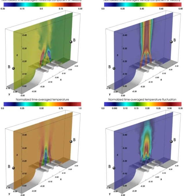
TrioCFD has been validated with LES of WAJECO and PLAJEST jet mixing experiments, in order to evaluate the thermal fatigue on a stainless metal plate. Numerical results have shown a good agreement with sodium and water experiments in most cases [34]. Figure 7 gives an overview of the results.
Figure 7. Visualizations of WAJECO results (TrioCFD calculation). 5. CONCLUSIONS
In this paper, the TrioCFD code developed by the CEA since the early 1990s has been presented. This code has an object-oriented architecture built in C++ language, and offers numerous physical models and numerical methods. TrioCFD is being especially developed and optimized for turbulence applications in industrial environment. Thermalhydraulics is a central subject targeted by TrioCFD users for it is specifically related to nuclear reactors flows. A substantial effort has been made during the last years, and is still in progress,
in order
to improve and diversify the turbulence models in the code. TrioCFD is permanently improved and validated within the CEA laboratory involved in its development, through rigorous automated Verification and Validation procedures. V&V ensures a good stability of the code and avoids
regression in the results quality as the code develops, by systematically comparing the calculationsfrom one version to the following. Furthermore,
s
ome user recommendations for flow simulations are extracted from the V&V experience, leading
to strong confidence in the code to produce successful studies. For these reasons TrioCFD constitutes
anappealing
CFD tool, especially employed to perform analyses of turbulent flows and heat transfers in portions of nuclear facilities. Some of the typical recent industrial computations have been presented and show the wide range of physical flows that TrioCFD is capable to properly achieve. The code is at the same time in perpetual evolution and in a suitable state of validation. In 2015, TrioCFD is getting an open source code, which represents a major step in the project history. The main objectives of this evolution are to benefit to many other applications and to expand the user community.REFERENCES
[1] TrioCFD: http://www-trio-u.cea.fr
[2] U. Bieder and E. Graffard, Qualification of the CFD code Trio_U for full scale reactor applications, Nucl. Eng. Des., 238 (3), pp. 671-679 (2007).
[3] U. Bieder, G. Fauchet and C. Calvin, “High performance Large Eddy Simulation of turbulent flows around PWR mixing grids”, Proceedings of 16th
IEEE International Conference on High Performance Computing and Communications (HPCC 2014) - First International Workshop on HPC-CFD in Energy/Transport Domains, Paris, France (August 2014).
[4] W. L. Oberkampf, T. G. Trucano, and C. Hirsch, Verification, validation, and predictive capability in computational engineering and physics, Appl. Mech. Rev., 57 (5), pp. 345-384 (2004).
[5] American Institute of Aeronautics and Astronautics, Guide for the Verification and Validation of Computational Fluid Dynamics Simulations, Technical report (G-077-1998), AIAA (1998).
[6] P.J. Roache, Verification and Validation in Computational Science and Engineering, Hermosa Publishers, Albuquerque, New Mexico (1998).
[7] CEA/DEN/DANS/DM2S/STMF/LMSF, Trio_U User’s Manual v1.7.0 (2014).
[8] C. Calvin, O. Cueto and P. Émonot, “An object-oriented approach to the design of fluid mechanics software”, ESAIM-Math. Model. Num., 36 (5), pp. 907-921 (2002).
[9] P. Émonot, Méthodes de volumes éléments finis : applications aux équations de Navier-Stokes et résultats de convergence, PhD thesis, Université Lyon I (1992).
[10] S. Heib, Nouvelles discrétisations non structurées pour des écoulements de fluides à incompressibilité renforcée, PhD thesis, Université Paris VI (2003).
[11] A. Chatelain, Simulation des Grandes Échelles d’écoulements turbulents avec transferts de chaleur, PhD thesis, Grenoble INP (2004).
[12] T. Fortin, Une méthode Éléments Finis à décomposition L2 d’ordre élevé par la simulation d’écoulement diphasique bas Mach, PhD thesis, Université Paris VI (2006).
[14] PETSc: http://www.mcs.anl.gov/petsc/
[15] M. Chandesris, A. d’Hueppe, B. Mathieu, D. Jamet and B. Goyeau, “Direct numerical simulation of turbulent heat transfer in a fluid-porous domain”, Phys. Fluids, 25 (12), pp. 125110 (2013). [16] L. Prandtl, “Über die ausgebildete Turbulenz”, J. Appl. Math. Mech., 5 (2), pp. 136-139 (1925). [17] B. E. Launder and D. B. Spalding, “The numerical computation of turbulent flows”, Comput.
Methods in Appl. Mech. Eng., 3 (2), pp. 269-289 (1974).
[18] U. Bieder, F. Falk and G. Fauchet, LES analysis of the flow in a simplified PWR assembly with mixing Grid, Prog. Nucl. Energy, 75, pp. 15-24 (2014).
[19] U. Bieder, F. Falk and G. Fauchet, CFD analysis of the flow in the near wake of a generic PWR mixing grid, Ann. Nucl. Energy (2014).
[20] J. Smagorinsky, “General circulation experiments with the primitive equations”, Month. Weath. Rev., 93, pp. 99-165 (1963).
[21] F. Nicoud and F. Ducros, Subgrid-scale stress modelling based on the square of the velocity gradient tensor, Flow Turb. Comb., 62, pp. 183-200 (1999).
[22] J. O. Hinze, Turbulence, MacGraw-Hill (1959).
[23] B. A. Kader, “Temperature and concentration profiles in fully turbulent boundary layers”, Int. J. Heat Mass. Transf., 24 (9), pp. 1541-1544 (1981).
[24] PRACE: http://www.prace-ri.eu/
[25] METIS: http://glaros.dtc.umn.edu/gkhome/metis/metis/overview/
[26] S. Schlesinger, “Terminology for Model Credibility”, Simulation, 3 (3), pp. 103-104 (1979). [27] T. Höhne, S. Kliem and U. Bieder, “Numerical modelling of a buoyancy-driven flow experiment at
the ROCOM test facility using the CFD codes CFX and Trio_U”, Nucl. Eng. Des., 236 (12), pp. 1309-1325, 2006.
[28] OECD, Assessment of Computational Fluid Dynamics (CFD) for Nuclear Reactor Safety Problems, NEA/CSNI/R(2007)13 (2008).
[29] U. Bieder, G. Fauchet, S. Bétin, N. Kolev and D. Popov, “Simulation of mixing effect in a VVER-1000 reactor”, Nucl. Eng. Des., 237 (15-17), pp. 1718-1728 (2007).
[30] U. Bieder, C. Calvin and H. Mutelle, “Detailed thermalhydraulic analysis of induced break severe accidents using the massively parallel CFD code Trio_U/PRICELES”, Proceedings of 5th International Conference on Supercomputing in Nuclear Applications (SNA-2003), Paris, France (September 2003).
[31] L. Ishay, G. Ziskind, U. Bieder and A. Rashkovan, “Nuclear reactor containment flows - Modelling of stable stratified layer erosion by a turbulent jet”, Proceedings of 16th International Topical Meeting on Nuclear Reactor Thermal Hydraulics (NURETH-16), Chicago, USA (September 2015).
[32] U. Bieder, V. Barthel, F. Ducros, P. Quéméré and S. Vandroux, “CFD calculations of wire wrapped fuel bundles: modeling and validation strategies”, Workshop Proceedings of Computational Fluid Dynamics for Nuclear Reactor Safety Applications (CFD4NRS-3), Bethesda, USA (September 2010).
[33] D. Tenchine, V. Barthel, U. Bieder, F. Ducros, G. Fauchet, C. Fournier, B. Mathieu, F. Perdu, P. Quéméré and S. Vandroux, “Status of Trio_U code for sodium cooled fast reactors”, Nucl. Eng. Des., 240, pp. 307–315 (2012).
[34] P.-E. Angeli, “Large-Eddy Simulation of thermal striping in WAJECO and PLAJEST experiments with TrioCFD”, Proceedings of 16th International Topical Meeting on Nuclear Reactor Thermal Hydraulics (NURETH-16), Chicago, USA (September 2015).