HAL Id: hal-03221364
https://hal.inria.fr/hal-03221364
Submitted on 8 May 2021
HAL is a multi-disciplinary open access
archive for the deposit and dissemination of
sci-entific research documents, whether they are
pub-lished or not. The documents may come from
teaching and research institutions in France or
abroad, or from public or private research centers.
L’archive ouverte pluridisciplinaire HAL, est
destinée au dépôt et à la diffusion de documents
scientifiques de niveau recherche, publiés ou non,
émanant des établissements d’enseignement et de
recherche français ou étrangers, des laboratoires
publics ou privés.
A True Inline Coaxial-Cavity Filter with Two
Symmetric Zeros
Stefano Tamiazzo, Giuseppe Macchiarella, Fabien Seyfert
To cite this version:
Stefano Tamiazzo, Giuseppe Macchiarella, Fabien Seyfert. A True Inline Coaxial-Cavity Filter with
Two Symmetric Zeros. IEEE Microwave and Wireless Components Letters, Institute of Electrical and
Electronics Engineers, 2021, pp.4. �10.1109/LMWC.2021.3064201�. �hal-03221364�
Abstract— This work deals with the design of true inline filters
with two symmetric transmission zeros. A new filters category named “path filters” is introduced (including the considered filters), his general features are discussed and analyzed and a general method for the synthesis of the low-pass prototype network is proposed. To validate the proposed design approach, a coaxial-cavity filter with a true inline topology exhibiting two symmetrical transmission zeros has been designed and fabricated. The realized prototype shows a response in good agreement with the theory.
Index Terms— inline filters, coaxial resonators, transmission
zeros, prototype synthesis.
I. INTRODUCTION
OST applications of microwave filters in recent years are requiring increasingly compact, lightweight, and selective devices. For this reason, the research has focused on filters with simple topologies allowing the introduction of transmission zeros, even very close to the passband. As a result, many examples of filter realizations featuring the above characteristics have appeared in the literature, implemented in the most popular fabrication technologies [1]-[5].
A very convenient topological solution widely adopted since a long time is the inline configuration. As well know, this topology allows basically an all-pole characteristic, i.e., no transmission zeros can be introduced in the response. However, several variants of the basic configuration have been recently proposed, to allow the introduction of transmission zeros. It can be mentioned the configurations with frequency dependent couplings [6], some implementations of extracted-pole topology [7] and the use of strongly-coupled resonators [8]-[9]. However, all these solutions require a more or less marked deviation from the “true” inline configuration.
In this work we introduce a new class of filters, that we have called “path filters” (for the analogies with the family of path graphs [10]), featuring the true inline topology but with the source and load placed inside (instead of being the first and last node as in all pole filters). In general, this topology cannot be synthesized from the usual characteristic polynomials producing the generalized Chebycheff characteristic, unless further constraints on the derived polynomials are imposed. We have here defined the constraints allowing up to two imaginary
Manuscript received February 15, 2021; accepted March 1, 2021.
This article has been presented at IEEE MTT-S International Microwave Symposium (IMS 2020), Atlanta, GA, USA, June 6–11, 2021. (Corresponding
author: Giuseppe Macchiarella)
S. Tamiazzo is with Commscope, Via Archimede, Agrate Brianza (Mi) – Italy (e-mail: [email protected]).
transmission zeros. Moreover, a procedure for the synthesis of the lowpass prototype has been developed, starting with the synthesis of the folded or transversal forms, followed by suitable matrix transformations.
Using the novel approach, the design and fabrication of a true inline filter of order 10 with two symmetric transmission zeros, has been carried out in coaxial technology. The realized prototype has been used to validate the design approach for path filters here proposed.
II. THE “PATH FILTERS”
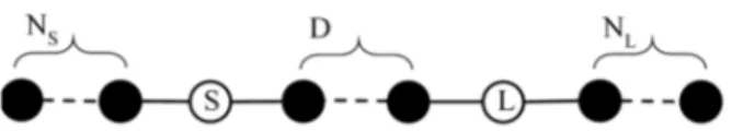
Fig. 1 shows the general configuration of path filters.
Fig. 1. General configuration of Path Filters. Each black node represents a resonator, the lines are the coupling inverters, the white nodes are the source and load.
This configuration is composed of three blocks of resonators, separated by source and load. The number of resonators before the source and after the load are NS and NL
respectively, while the internal ones are D. The overall number of resonators is then N=NS+D+NL. We can observe that, for the
minimum path rule [12], path filters allow introducing exactly M=NS+NL transmission zeros in the response.
In general, we can approach the synthesis of this filter class starting with the evaluation of the characteristic polynomials (F(s), P(s), E(s)) determining the Generalized Chebycheff response in the normalized frequency domain s [11]. However, it can be shown that an additional constraint must be imposed on these polynomials. Assuming the filter response symmetric (i.e. S11=S22) this constraint requires that each imposed
transmission zero is also a double eigenvalue of the synthesized network. To demonstrate this requirement, let’s start by the elements of ABCD and Z matrices of the filter, that can be expressed as polynomials ratios [11]:
A=D=a(s)/P(s), B=b(s)/P(s), C=c(s)/P(s)
Z11=Z22=a(s)/c(s), Z12=P(s)/c(s) (1) Assume now that jz is a root of P(s) (i.e., is a transmission zero). Due to the topology of the path filters, at the frequency
G. Macchiarella is with Dipartimento di Elettronica, Informazione e Bioingneria, Politecnico di Milano, 20133 Milano, Italy (e-mail:
F. Seyfert is with INRIA, 06902 Sophia-Antipolis, France (e-mail: [email protected])
A True Inline Coaxial-Cavity Filter with Two
Symmetric Zeros
Stefano Tamiazzo, Giuseppe Macchiarella, Fellow, IEEE, Fabien Seyfert
of the zero a short circuit is produced in parallel to source and load (Z11= Z22=0). Consequently, a(jz)=0 and c(jz)≠0. Moreover, the assumed lossless condition requires the determinant of ABCD matrix equal to 1, that is:
2 2
a s
P s
b s c s
(2) From (2) descends that jz must also be a double root of b(s). As the roots of b(s) are also the eigenvalues of the filter shunt model [11], we have demonstrated that every transmission zero of a symmetric path filter, synthesized with shunt equivalent resonators, must also be a double eigenvalue of the filter equivalent circuit. Note that, being the eigenvalues of a lossless filter imaginary, also the transmission zeros introduced by path filters must be imaginary, as above assumed. Moreover, being Nz= NS+NL the number of double eigenvalues, N>2Nz impliesthat D≥NS+NL.
From what has been said above, the synthesis of path filters with Chebycheff (equiripple) response requires an additional constraint (for each transmission zero), in addition to those defining the usual filter specifications. Unfortunately, no degree of freedom is available after the requirements have been set, so we must give up assigning one of them to make the synthesis of path filters possible. In this work we have used the return loss parameter to get the characteristic polynomials of path filters exhibiting a symmetric response with two zeros (±jz). Note
that, in this case, NS+NL≤2 (the zeros can be extracted both at
source (load) side or one at source and one at load). A. Polynomials Evaluation
As pointed out above, the condition for synthesizing a path prototype is to have eigenvalues of multiplicity 2 in correspondence of each assigned pair of symmetric transmission zero. However, this condition is in general not satisfied if the characteristic polynomials are computed with the classical methods [10]. We have then developed an empirical procedure that, although not formally proven, has been assessed on the base of several examples up to NS+NL=2. It consists of
the following steps:
- Assign the filter order and the desired transmission
zeros (imaginary)
- Evaluate the reflection characteristic polynomial F(s)
- Compute the filter eigenvalues (represented by the
roots of the denominator polynomial of the filter admittance matrix) as function of the leading coefficient p0 of the transmission polynomial P(s)
- Select the value of p0 producing two coincident
eigenvalues at the frequencies of the transmission zeros.
Once p0 has been determined, all the characteristic polynomials are defined. However, as observed before, the return loss cannot be assigned freely because it depends on p0. The not assignable return loss level represents the main drawback of the proposed procedure. We note however that in case the assigned transmission zeros are relatively close to the passband, the resulting level of return loss is generally acceptable. Fig. 2 gives an idea of the return loss obtained for three values of the assigned transmission zeros and N varying from 5 to 15. It can be observed that RL is little dependent on N and increases by moving the transmission zeros away from the passband.
Fig. 2. Return Loss obtained from the computed polynomials for three different assignment of the transmission zeros and N ranging from 5 to 15.
B. Synthesis of the path prototype
In line of principle, the synthesis of the path prototype could be approached with the evaluation of the transversal prototype, followed by suitable matrix transformations. Unfortunately, the transversal form of filters with double eigenvalues cannot be synthesized using the classical method given in the literature [13], which holds only for networks with simple eigenvalues. We have then used the folded canonical form as initial prototype [11], which can be synthesized using the extractions method [14], not based on the eigenvalues computation. The coupling matrix of the folded prototype is then suitably reconfigured to get the coupling matrix of the path filter in Fig. 1. To this end, first the conversion to the Wheel form is carried out using the algorithm in [15]. Then a sequence of matrix rotations is applied, to get out a triplet form from the load and moving it up to the source (the same technique used in [15]). When the triplet arrives in the final position, all cross couplings disappear, and the "path" topology is obtained.
III. FILTER DESIGN
The filter to be designed has the following electrical requirements:
Passband: 3394-3806 MHz, Return Loss ≥18 dB Order (number of resonators): 10
Stopband attenuation: >30 dB for |f-f0|>230 MHz
To fit the attenuation requirements two transmission zeros must be placed symmetrically above and below the passband at 3835 MHz and 3368.3 MHZ. Note that the rejection actually presented by the synthesized path filter depends on the resulting return loss, that cannot be assigned a priori. At the end of the polynomials evaluation, the fulfillment of the above requirements must then be verified before proceeding with the synthesis of the prototype.
The reflection zeros defining the monic polynomial F(s) are first evaluated from the normalized transmission zeros (±j1.13268): zF=[0.9917, 0.9194, 0.7562, 0.4994, 0.1747, -0.9917, -0.9194, -0.7562, -0.4994, -0.1747]
The polynomial P(s) is defined as function of the unknown highest degree coefficient p0: P(s)=p0(s2+1.283).
Finally, the polynomial E(s) defining the filter poles can be computed by spectral factorization from the Feldtkeller equation (lossless condition) [11]: E(s)E*(s)=P(s)P*(s)+F(s)F*(s). The filter eigenvalues are the roots of polynomial b(s) which can be evaluated from the characteristic polynomials as described in [11]. We can then represent the eigenvalues as
Number of resonators Re turn L os s (dB) z=±1.15 z=±1.1 z=±1.05
function of the real parameter p0 (Fig. 3). It can be observed that two pairs of symmetrical eigenvalues cross for p0=0.041803.
Fig. 3. Computed filter eigenvalues as function of p0.
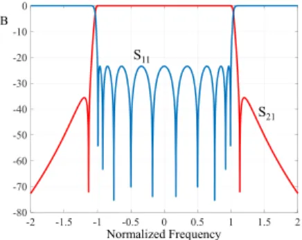
Moreover, at the crossing points the eigenvalues coincide with the assigned transmission zeros (±1.13268). For the computed value of p0 the return loss is 23.4407 dB and the condition for implementing the filter with the path topology is satisfied. The response in the normalized domain is shown in Fig. 4. It can be observed that return loss is larger than 18 dB while attenuation in the stopbands exceeds 30 dB. The filter requirements are then satisfied, and it is possible to proceed with the synthesis of the path filter.
We have assumed NS=2 and NL=0. The synthesis of the
prototype is carried out with the procedure described before obtaining the normalized coupling matrix of the desired path filter: Mi,i=0, Ms2=0.67, Ms3=0.802, M12=1.133, M23=0,
M34=0.604, M45=0.526, M56=0.525, M67=0.531, M78=0.545,
M89=0.596, M910=0.862, M10L=1.046.
Fig. 4. Computed polynomial response of the normalized prototype with
p0=0.041803 (RL=23.4407 dB)
The last step of the synthesis is the de-normalization of the normalized prototype defined by the computed coupling matrix. In this step we determine the coupling coefficients and the resonating frequencies of the filter in the bandpass domain (Fig. 5), that are used for dimensioning the physical structure implementing the filter.
Fig. 5. De-normalized equivalent circuit of the path filter. Black circles represent the resonators (all resonating at f0=3594.1 MHz). The numbers above
or below the solid lines are the coupling coefficients between the resonators.
For the physical realization of the filter (Fig. 6), a comb structure inside a box of height 19 mm has been employed. The coupled resonators are square cylinders of size 3.5 mm x 3.5
mm and of various heights (averaging 18 mm). The quality factor of the fundamental resonant mode (3.6 GHz) is about 2500 and adjacent rods are coupled by proximity and possibly connected by a thin metal bar in places where strong couplings are required. All input and output couplings (three in this case, two at the source end and one at the load end) are realized through suitable lengths of transmission (strip) lines soldered to the rods 2, 3 and 10 (Fig. 6), at a suitable distance from the base (ground plane).
Fig. 6. Fabricated structure of the path filter. The resonators are the numbered square cylinders (1 and 2 are those realizing the transmission zeros).
Fig. 7. Measured response of the fabricated prototype.
Fig. 7 shows the measured response of the realized prototype Although the agreement with the polynomial response of fig. 4 is good, the limited range and resolution of the adopted tuning elements prevented from a better ‘shaping’ of the return loss curve.
IV. CONCLUSION
In this paper an introduction to the design of a class of true in line filters with up two symmetric transmission zeros has been given, along with a practical realization in the 3.4 – 3.8 GHz band. This class of filters appears to be promising for the realization of symmetrical frequency responses usually required in TDD radios for cellular networks operating in that range of frequencies. Compared to the canonical cross coupled alternatives, there is no need in path filters to implement negative couplings, usually associated with spurious resonances and tolerance issues. Finally, it must be emphasized that the design approach proposed here represents the first analytical solution for the class of filters considered. Indeed, previous works dealing with this topology [16] address the synthesis of the low-pass prototype using optimization techniques. We are currently working on the extension of the path filters synthesis to a larger number of transmission zeros (not necessarily symmetric).
-2 -1.5 -1 -0.5 0 0.5 1 1.5 2 -80 -70 -60 -50 -40 -30 -20 -10 0 Normalized Frequency dB S11 S21 S L 0.0517 0.0736 0.1253 0.1296 0.0691 0.0602 0.0601 0.0608 0.0627 0.0682 0.0987 3200 3300 3400 3500 3600 3700 3800 3900 4000 Frequency (MHz)
Measured Frequency Response
-100 -90 -80 -70 -60 -50 -40 -30 -20 -10 0 m3: 3800 MHz -1.1 dB m2: 3596 MHz -0.58 dB m1: 3400 MHz -0.95 dB F1 F1S 11 S21
REFERENCES
[1] S. Amari, G. Macchiarella “Synthesis of In-Line Filters with Arbitrarily Placed Attenuation Poles by Using Non-Resonating Nodes” in IEEE Trans. Microw. Theory Techn., Vol. MTT-53, n.10, October 2005, pp. 3075-3081
[2] S. Amari, U. Rosenberg and R. Wu, "In-line pseudoelliptic band-reject filters with nonresonating nodes and/or phase shifts," in IEEE
Trans. Microw. Theory Techn., vol. 54, no. 1, pp. 428-436, Jan. 2006
[3] S. Bastioli, R. V. Snyder, and P. Jojic, "High power in-line pseudoelliptic evanescent mode filter using series lumped capacitors," in Proc. 41th Eur. Microw. Conf. (EuMC), Manchester, 2011, pp. 87-90
[4] S. Bastioli and R. V. Snyder, "Inline Pseudoelliptic TE01δ Mode Dielectric Resonator Filters Using Multiple Evanescent Modes to Selectively Bypass Orthogonal Resonators," in IEEE Trans.
Microw. Theory Techn., vol. 60, no. 12, pp. 3988-4001, Dec. 2012
[5] S. Cogollos, V.E. Boria et al., "Design procedure of low-cost substrate microstrip filters based on nonresonating nodes", in IEEE
MTT-S Int. Microw. Symp. Dig, Jun. 2008, pp. 543-546.
[6] Y. He, G. Macchiarella, Z. Ma, L. Sun and N. Yoshikawa, "Advanced direct synthesis approach for high selectivity in-line topology filters comprising N-1 adjacent frequency-variant couplings" IEEE Access, vol. 7, pp. 41659-41668, Mar. 2019 [7] G. Macchiarella, G.G. Gentili, C. Tomassoni, S. Bastioli, and R.V.
Snyder, “Design of Waveguide Filters with Cascaded Singlets Through a Synthesis-Based Approach,” IEEE Trans. Microw.
Theory Techn., vol. 68, no. 6, pp. 2308-2319, Jun. 2020
[8] G. Macchiarella, S. Bastioli, R. Snyder, “Design of In-line Filters with Transmission Zeros Using Strongly-Coupled Resonators Pairs
IEEE Trans. Microwave Theory Tech., vol. 66, N. 8, pp. 3836-3846,
Aug. 2018
[9] S. Bastioli, R. V. Snyder and G. Macchiarella, "Design of In-Line Filters with Strongly Coupled Resonator Triplet," in IEEE Trans.
Microw. Theory Techn., vol. 66, no. 12, pp. 5585-5592, Dec. 2018
[10] R. Diestel, Graph Theory, Graduate Texts in Mathematics, Vol. 173. Springer-Verlag, Heidelberg, 2017
[11] R. J. Cameron, C. M. Kudsia, and R. R. Mansour, Microwave Filters
for Communication Systems. Hoboken, NJ, USA: John Wiley &
Sons, 2007
[12] S. Amari, "On the maximum number of finite transmission zeros of coupled resonator filters with a given topology," IEEE Microw.
Guided Wave Lett., vol. 9, no. 9, pp. 354-356, Sept. 1999
[13] R. J. Cameron, “Advanced Coupling Matrix Synthesis Techniques for Microwave Filers”, IEEE Trans. Microw. Theory Techn., vol. 51, no. 1, pp. 10, Jan. 2003
[14] Cameron, R.J. “General prototype network synthesis methods for microwave filters” ESA Journal, vol. 6, pp. 193–207, June 1982 [15] S. Tamiazzo and G. Macchiarella, “An analytical technique for the
synthesis of cascaded N-tuplets cross-coupled resonators microwave filters using matrix rotations,” IEEE Trans. Microw.
Theory Techn., vol. 53, no. 5, pp. 1693–1698, May 2005.
[16] T. Zhang, Z. Long, L. Zhou, M. Qiao, F. Hou and M. Tian, "Realization of Even Transmission Zeros for Filter Without Cross-Couplings," in IEEE Trans. Microw. Theory Tech., vol. 66, no. 12, pp. 5248-5259, Dec. 2018.