HAL Id: hal-00703636
https://hal.archives-ouvertes.fr/hal-00703636
Submitted on 4 Jun 2012
HAL is a multi-disciplinary open access
archive for the deposit and dissemination of
sci-entific research documents, whether they are
pub-lished or not. The documents may come from
teaching and research institutions in France or
abroad, or from public or private research centers.
L’archive ouverte pluridisciplinaire HAL, est
destinée au dépôt et à la diffusion de documents
scientifiques de niveau recherche, publiés ou non,
émanant des établissements d’enseignement et de
recherche français ou étrangers, des laboratoires
publics ou privés.
Method Family Description and Configuration
Rebecca Deneckere, Elena Kornyshova, Colette Rolland
To cite this version:
Rebecca Deneckere, Elena Kornyshova, Colette Rolland. Method Family Description and
Configura-tion. ICEIS, 2011, Beijing, China. pp.384-387. �hal-00703636�
METHOD FAMILY DESCRIPTION AND CONFIGURATION
Deneckère Rébecca, Elena Kornyshova, Colette Rolland
Centre de Recherche en Informatique, Université Paris 1 Panthéon-Sorbonne, 90 rue de Tolbiac, 75013 Paris, France (denecker, kornyshova, rolland)@univ-paris1.fr
Keywords: Method Component, Method Line, Method Family, Configuration, Decision-Making.
Abstract: The role of variability in Software engineering grows increasingly as it allows developing solutions that can be easily adapted to a specific context and reusing existing knowledge. In order to deal with variability in the method engineering (ME) domain, we suggest applying the notion of method families. Method components are organized as a method family, which is configured in the given project. As variability relates to variation points, our proposal is to consider the method family configuration as a decision-making (DM) process. We illustrate our approach by a method family dealing with scenario elicitation.
1 INTRODUCTION
Over the decades, variability in Software Engineering has become increasingly important. The notion of software variability is defined as the ability of a software system to be changed, customized or configured to a specific context (Van Gurp, 2000). (Taylor, 1964) states that variability modeling is useful for both variability acquisition - to discover variation points in a problem - and variability analysis - to evaluate the applicability of each identified variant in a given context and situation. The great amount of features observed in modern software systems and the difficulty in understanding how the technical details of individual choices affect stakeholder intentions about the system lead to the need to explore and analyze variability at a higher level of abstraction.
This increasing variability in software engineering has led to the establishment of the Product lines concept which allows managing commonalities and variability. This leads to two major advantages: the reuse of common parts and the adaptation of products to different customers and various organisational settings (Svahnberg et al., 2001).
Given the duality that exists between Product and Process (Rolland, 2010), our motivation is to investigate the variability concept in method engineering (ME). Our position is that method families do exist today in companies and could beneficially be handled by using the variability.
The foregoing suggests a move away from this construction of methods ‘on the fly’ to the management of a set of similar components considered as a whole, or as a method family. Our proposal is to organize these components into method families to manage variability and commonalities in order to promote the reuse and the adaptability of method families. As variability relates to variation points, we propose to foresee the method family configuration problem as a decision-making (DM) problem. A DM problem is characterized by the presence of several alternatives. In our case, alternatives are method components which are variables in a given method family, that is to say, when the method engineer has a possibility to choose between several method components. We illustrate the method family description and configuration within an example dealing with scenario elicitation.
This paper is organized as follows. The first section foresees the notion of method family and its intrinsic variability. Section 2 details three techniques used for configuring method families. Section 3 illustrates these techniques. We conclude in Section 4.
2 CAPTURING VARIABILITY IN
METHOD FAMILY
We understand a method family to be a collection of method components meeting a common goal but in
different ways. For instance, the intention ‘Write a scenario’ can be achieved through the execution of two different method components that allow writing a scenario in free prose or with the help of a predefined template. The variability across these two components is obvious. However, there is a commonality between them as well as the intention is the same: to obtain a scenario.
In this work, we propose a modelling formalism called MAP to capture variability across method families in an intentional manner. Each map (i.e. each method family) can then be configured following specific criteria in order to obtain an adaptable method (i.e. a method line).
A map is a process model expressed in a goal driven perspective. This formalism allows specifying process models in a flexible way by focusing on the process intentions, and on the various ways to achieve each of these intentions. Therefore, it has a teleological nature (it takes into account the teleological behavior of the process execution). It describes the intentions (goals, objectives) associated to the result that the designer wants to achieve (Taylor, 1964). In this way, the MAP model presupposes decisions which concern intentions, strategies or elementary actions. A map expression provides a synthetic view of the variability of a process in a relatively easy to understand way. Variations are revealed in two ways, by the gradual movement down the different levels of a top map, and by the alternative strategies/paths available at a given map level (C. Rolland, 2007).
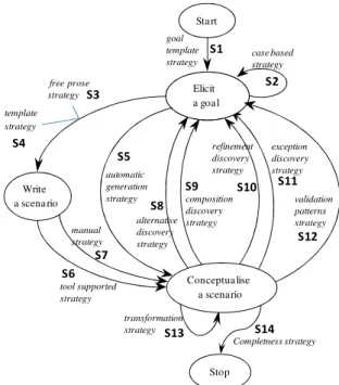
Let’s look more closely to the Scenario Elicitation Situational Method(SESM) example (see Figure 1). It is based on a map defined in (Ralyte and Rolland, 2001) which was created to support the elicitation of functional system requirements in a goal-driven manner and to conceptualize them using textual devices such as scenarios or use cases. This map contains three main intentions, namely ‘Elicit a Goal’, ‘Write a Scenario’ and ‘Conceptualize a Scenario’. The original map from (Ralyte and Rolland, 2001) was defined with the assembly of two method components, namely the L’écritoire and the SAVRE ones.
• The L’Ecritoire method component (Rolland, Souveyet and Ben Achour, 1998) provides guidelines to discover functional system requirements expressed as goals and to conceptualize these requirements as scenarios describing how the system satisfies the achievement of these goals.
• The SAVRE method component (Maiden, 1998) provides guidelines to discover exceptions in the functioning of a system under design caused by
human errors. It generates scenarios corresponding to the system requirements and identifies, through an analysis of these scenarios, possible exceptions caused by human errors.
Assembly techniques have been used to be able to put the two method components into the same map. Specific operators, like intention-merging or strategy-addition for instance, have been used to create this situational method. When looking at this map from the method family point of view, we can notice that we can already derive two method lines corresponding to the two methods used to assemble it.
Elicit a Use Case alternative discovery strategy composition discovery strategy template strategy free prose strategy tool supported strategy manual strategy goal template strategy Elicit a goal refinement discovery strategy case based strategy Start exception discovery strategy automatic generation strategy transformation strategy validation patterns strategy Write a scena rio Stop Conceptua lise a scenario S1 S2 S3 S4 S5 S6 S7 S8 S9 S10 S11 S12 S13 Completness strategy S14
Figure 1. Scenario Elicitation Situational Method
3 CONFIGURING AN
APPLICATION METHOD
Goal-oriented models have a teleological nature (it takes into account the teleological behaviour of a process execution). In this way, they presuppose decisions which concern different possibilities to carry out the given process. Each decision is a variation point. We suggest to foresee these models as method families as they contain common and variable elements. Each method family can be customized in a given project into a method line. The method line customization is realized by selecting a particular method component in each variation point. Our proposal is to use different DM techniques for guiding this selection. In this way, we foresee the method line customization as a decision-making problem.
A DM problem is defined by the presence of alternatives. The concept of alternative designates the decision object. Any decision involves at least two alternatives that must be well identified. Alternatives are compared between them according to one or more criteria. Based on this, DM methods can be monocriterion or multicriteria. Using a single criterion is most widespread but it is not sufficient when the consequences of the alternatives to be analyzed are important (Roy, 1996). Multicriteria DM methods, in contrast to a monocriterion approach, allow a more in-depth analysis of the problem because they consider various aspects. These methods deal with indicators having different nature (quantitative or qualitative). However, they are more complicated as the indicators’ values must be aggregated into a general value or function (Roy, 1996).
In our case, alternatives are candidate method components in each variation point, and criteria are indicators characterizing the given project situation.
Based on this, we suggest three kind of configuration: Method components subset selection, Complete method line selection, and Step by step method components selection.
Method components subset selection uses the
indicator(s) to simplify the Map by suppressing some components. This kind of configuration allows to select a sub-set of alternatives (A’) from A based of the values of G in a given project. For instance, it can be a selection of method components requiring a low expertise degree.
Complete method line selection helps to select,
right from the start of the navigation, between all the possible method lines. The first step is to measure the indicator values for each method line based on values associated to method components which compose this line. Therefore, the alternatives are method lines (A’’) and criteria are aggregated values (G’’). For instance, all method components may be measured according to the duration criteria. First, the duration of all possible method lines is calculated (as a sum of its components duration). Then, a method line having the lowest duration is selected.
Step by step method components selection
guides each of the engineer steps, one by one - which is the initial and usual way to use a method family. In this case, the sub-set of method components (available at the given step) is considered (A’’’). For instance, when the engineer must select a method for writing scenario, he has got to choose between the free prose strategy and the template strategy (S3 and S4 components of SESM).
All of these guidance types may be used with one or more indicators.
The indicators typology is based essentially on the characteristics of IS development projects (Van Slooten and Hodes, 1996). A set of indicators and
their possible values was deduced from these characteristics (Deneckere and Kornyshova, 2010). For instance, the guidance between components may depend on their complexity degree, the number of stakeholders, the expert role and so on. Others indicators may also be deduced from Non-Functional Requirement (NFR) (Santos, Pimentel, Castro, Sanchez and Pastor, 2010). For instance, the duration or the cost of a component execution may influence the component selection guidance.
Indicators can be quantitative or qualitative. The use of values increases the possibility of automatic guidance.
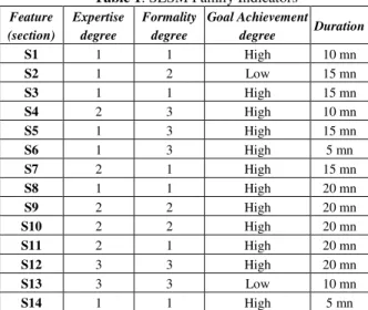
To illustrate our proposal, we applied this typology to the SESM family of Figure 1. In this example, we have selected four indicators: Expertise degree, Formality degree, Goal achievement degree and Duration. Table 1 shows the values of each of these criteria applied to each feature of the SESM family.
Table 1. SESM Family Indicators
Feature (section) Expertise degree Formality degree Goal Achievement degree Duration S1 1 1 High 10 mn S2 1 2 Low 15 mn S3 1 1 High 15 mn S4 2 3 High 10 mn S5 1 3 High 15 mn S6 1 3 High 5 mn S7 2 1 High 15 mn S8 1 1 High 20 mn S9 2 2 High 20 mn S10 2 2 High 20 mn S11 2 1 High 20 mn S12 3 3 High 20 mn S13 3 3 Low 10 mn S14 1 1 High 5 mn
We apply three techniques in order to configure the SESM method family.
Method Components Subset Selection. This technique allows defining a method line by selecting a subset of features following one or multiple criteria. For instance, if we apply the single criteria of Expertise degree with a preference for a Low value (equal to 1). The obtained multi-path may be formalized as follows. MPStart-Stop= S1. ((S2) * .((S3.S6) ∪ S5)) ∪ ((S2)* .((S3.S6) ∪ S5) . (S8.(S2)* .((S3.S6) ∪ S5))* . S14
The obtained method line can be used by engineers having a low degree of expertise in the scenario conceptualization. By using this simpler
map, the engineer has fewer variants to take into account and the further guidance is easier.
Path Selection. There is a possibility to choose a path, directly from the beginning of the process. For instance, the Duration criteria will help to obtain a specific method line which is the quickest to perform. The time factor will help to choose the following path as the chosen method line.
PStart-Stop=S1.S5.S14
Choosing this guidance, the engineer executes the method line which corresponds to the lowest duration. He does not have a possibility to change the used method components during the execution.
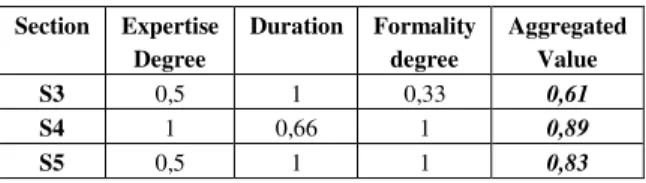
Atomic Step Selection. This technique helps to keep the intentional nature and all the powerfulness of the map model. For instance, the navigation through the Map leads the engineer to execute, at his satisfaction, the section S2 (which helps him to elicit a goal with a case-based strategy). Four possibilities are offered to the engineer to go further in the process. He may execute the section which has the same target intention (S2) or go further in the Map to the intention Write a Scenario (S3, S4), or even go directly to Conceptualize a scenario (S5). As the intention ‘Elicit a Goal’ is fully satisfied, the indicator ‘Goal Achievement degree’ will guide him to suppress the first possibility. He then chooses to use three other criteria to customize his guidance, namely Duration, Expertise degree and Formality degree. These three indicators are quantitative and have different measure scales. In order to obtain the compatible scales for comparing them, the normalization must be applied. The normalized values are presented in the Table 2.
Table 2. Normalized Indicator Values
Section Expertise Degree Duration Formality degree Aggregated Value S3 0,5 1 0,33 0,61 S4 1 0,66 1 0,89 S5 0,5 1 1 0,83
The aggregated value of the indicators guides him to choose the section S3. That means that, the selected section requires the lowest expertise and formality degree and the lowest duration.
4 CONCLUSIONS AND FUTURE
WORKS
We introduce the notion of variability in method family. Method families bring together a set of
different components having the same main usage to facilitate their reuse and adaptation. We use the MAP intentional formalism to represent method families as a set of method component features and use variability through four types of feature relationships. Once the method family has been expressed with maps, the task of selecting the adapted method line is done by deciding which combinations of features are the most suited to the situation at hand, following criteria and several selection techniques.
Our future work consists of adapting the Map-editor tool and combining it with the Map-executor tool currently on development. This tool will support navigation in a map to select dynamically the feature most appropriate to the situation at hand.
REFERENCES
Deneckere, R. and Kornyshova, E., 2010. Process line configuration : an indicator-based Guidance of the Intentional Model MAP. EMMSAD’10, Hammamet, Tunisia.
Maiden, N.A.M., 1998. CREWS-SAVRE: Scenarios for Acquiring and Validating Requirements. Journal of Automated Software Engineering.
Ralyte, J. and Rolland, C., 2001. An assembly process model for method engineering. CAISE’01, Interlaken, Switzerland.
Rolland, C., Souveyet, C. and Ben Achour, C., 1998. Guiding Goal Modelling Using Scenarios. IEEE Transactions on Software Engineering, special issue on Scenario Management, Vol. 24, No. 12, pp 1055-1071
Rolland, C., 2007. Capturing system intentionality with maps. In the book Conceptual Modelling in Information Systems Engineering, J. Krogstie, A. Opdahl, S, Brinkkemper (Eds.).
Rolland, C., 2010. Method engineering : trends and challenges. RCIS’10, Invited Talk.
Roy, B., 1996. Multicriteria Methodology for Decision Aiding. Dordrecht, Kluwer Academic Publishers Santos, E., Pimentel, J., Castro, J., Sanchez, J., Pastor, O.,
2010. Configuring the Variability of Business Process Models Using Non-Functional Requirements. EMMSAD’10, Hammamet, Tunisia.
Svahnberg et al., 2001. On the notion of variability in Software Product Lines. Proceedings of the Working IEEE/IFIP Conference on Software architecture. Taylor, C., 1964. The Explanation of Behaviour. London:
Routledge.
Van Gurp, J., 2000. Variability in Software Systems, the key to Software Reuse. Licentiate Thesis, University of Groningen, Sweden.
Van Slooten, K., and Hodes, B., 1996. Characterising IS development projects. IFIP WG8.1 Conference on Method Engineering.