Advances in Membrane-Based Oil/Water Separation
by
Leonardo David Banchik
M.S., Mechanical Engineering
Massachusetts Institute of Technology, Cambridge, 2013
B.S., Mechanical Engineering
University of Nevada, Las Vegas, 2010
Submitted to the Department of Mechanical Engineering
in partial fulfillment of the requirements for the degree of
Doctor of Philosophy in Mechanical Engineering
at the
MASSACHUSETTS INSTITUTE OF TECHNOLOGY
February 2017
Massachusetts Institute of Technology 2017. All rights reserved.
AuthorSignature
red acted
Author
...
S g
a u
e r
d
c e
Department of Mechanical Engineering
October 20, 2016
Signature redacted
C ertified b y ...
...
...
John H. Lienhard V
Abdul Latif Jameel Pro sor, Depart ent of Mechanical Engineering
Thesis Supervisor
Accepted by...Signature
redacted
RohafimAbeyaratne
Chairman, Committee on Graduate Students
MASSAC S ITUTE
OF TECHNOWGY
FEB 15 2017
MITLibraries
77 Massachusetts Avenue
Cambridge, MA 02139 http://Iibraries.mit.edu/ask
DISCLAIMER NOTICE
Due to the condition of the original material, there are unavoidable
flaws in this reproduction. We have made every effort possible to
provide you with the best copy available.
Thank you.
The images contained in this document are of the
Advances in Membrane-Based Oil/Water Separation
by
Leonardo David Banchik
Submitted to the Department of Mechanical Engineering on October 20, 2016, in partial fulfillment of the
requirements for the degree of
Doctor of Philosophy in Mechanical Engineering
Abstract
Oil is a widespread pollutant from oil spills to industrial oily wastewater in the oil and gas, metalworking, textile and paper, food processing, cosmetics, and pharmaceutical in-dustries. A wastewater of particular concern is produced water, an oily waste stream from hydrocarbon extraction activities. Worldwide, over 2.4 billion US gallons of produced wa-ter is generated every day. Membrane technologies have emerged as the preferred method for treating these wastewaters; this has allowed operators to reclaim and reuse fresh water for potable, industrial, and agricultural use and to meet waste discharge regulations. Yet, despite their technological predominance, membranes can become severely fouled and ir-reversibly damaged when bulk and small stabilized oil droplets, emulsions, are present in intake streams. In this thesis, we seek to mitigate these deleterious effects through several means.
First we seek to better understand fouling by oil-in-water emulsions on conventional polymeric ultrafiltration membranes. We investigate the decrease in water production over time using model and actual produced water samples with varying solution zeta potentials and make meaningful recommendations to operators based on our observations. Next, we develop a robust multifunctional membrane which can in one step degrade organic pollutants and separate bulk and surfactant-stabilized oil/water mixtures while achieving high fluxes, high oil rejection, and high degradation efficiencies.
Finally, we investigate the potential of novel in-air hydrophilic/oleophobic microfiltration and reverse osmosis membranes for their anti-oil fouling performance relative to conventional hydrophilic/oleophilic membranes. Contrary to claims in literature of superior performance, we find that in-air oleophobicity does not aid in underwater anti-fouling due to surface reconstruction of mobile perfluoroalkyl chains in the presence of water. Based on these observations, we discuss opportunities for future research on oil anti-fouling membranes using fluorinated moieties.
Thesis Supervisor: John H. Lienhard V
Acknowledgments
This Institute has a slogan, Mens et Manus, Latin for Mind and Hand, which I tried to pursue in earnest during my academic journey. Because my Master's work had been mostly computational, Mens-style work, I decided to pursue work more associated with the Manus side of science for my doctorate. This work would involve much more hands-on experimentation and would hopefully yield readily applicable results. During my time at MIT, I have been fortunate to experience both styles of work, but I have many people to thank for supporting me through the steep learning curve associated with the transition from one work style to the other.
I wish to first thank my adviser, Prof. John H. Lienhard V, for his support in letting me pursue
the topics which interested me most - regardless of the slope of the learning curve. Additionally, it has been a pleasure to learn from Prof. Lienhard about asking the right research questions and communicating clearly through academic publications and presentations. I would also like to thank Prof. Lienhard for his guidance and financial support of the MIT Water Club, a club whose future
I was fortunate enough to help shape during my 2013 Co-Presidency. Prof. Lienhard has been a
strong ally of the club and has a genuine desire to support clubs on campus which operate at the intersection of the Energy-Water-Food nexus.
Along with Prof. Lienhard, I am very thankful for the other members of my doctoral committee: Prof. Alan T. Hatton, for his guidance associated with his deep knowledge of colloidal systems, and Prof. Gareth H. McKinley, for his critical eye which has considerably improved the work herein.
This work would not have been possible without funding from my sponsors, the King Fahd University of Petroleum and Minerals and the National Science Foundation Graduate Research Fellowship, and I am sincerely grateful for their financial support.
Early during this Manus-styled journey, I remember realizing that the resources necessary to perform much of the work in this thesis were scattered around the Institute in the form of specialized laboratory equipment and very knowledgeable researchers. I am deeply grateful for these researchers, many of whom would become future friends, for teaching me how to use the lab equipment and spending hours of their time to help guide me through new research territories. In particular I'd like to thank Gibum Kwon, Divya Panchanathan, and Talal Qahtan. Gibum was a great ally in the lab, helping me to spray coat my first hydrophilic-oleophobic membranes based on formulations in the literature which served as an important basis for the work in Ch. 3. Divya has been a close partner while working on Chs. 3-5; in addition to helping me perform some of the experiments, it's been fantastic to strategize future research steps with her. Talal Qahtan was a wonderful partner to work with on Ch. 3; he delivers quality experimental results, works hard to deliver results in a timely fashion, and has demonstrated creativity in his work.
I'd also like to thank Priya Moni, Minghui Wang, Rong Yang, and Hossein Sojoudi in Prof.
Karen Gleason's lab; Seyed Mahmoudi, Arindam Das, Paris Cox, Srinivas Subramanyam, and Brian Solomon in Prof. Kripa Varnasi's lab; Andrew Jones and Youngsoo Joong in Prof. Cullen Buie's lab; Simon Choong and Yi-Min Lin in Prof. Gregory Rutledge's lab; and Dayong Chen in Prof. Robert Cohen's lab. Special thanks also to Leslie Regan, Joan Kravit, and Una Sheehan in the MechE Department for always being available to chat about graduate school challenges and next steps.
I sincerely hope that every future team of which I am a part is as colorful, dynamic, helpful, and sincere as the Lienhard Lab. In no particular order, thanks are due to: Emily Tow, my fellow foul pal (our theses involved membrane fouling), for helpful discussions on experiments and invaluable critical feedback; David Warsinger for great feedback; Kishor Nayar for spiritual guidance & entrepreneurial chats; Hyung Won Chung for discussions and collaboration on pressure retarded osmosis; Jaichu Swaminathan for helpful discussions; Gregory Thiel and Adam Weiner for useful discussions and fruitful collaborations; Ronan McGovern for good feedback on a few works; Karim Chehayeb, Karan Mistry, Ed Summers, Urmi Roy, Omar Labban, Yvana Ahdab, and Quantum Wei for making life in the lab a lot more fun. Thanks are also due to my two UROPs, Joshua Emig and Hind Saleh who did some of the great work in Chs. 2 and 4, respectively. Christine Gervais was instrumental in ordering parts for my experiment and helping with many other administrative tasks, and Theresa Werth and Kate Anderson were reliable and fun to work with as well.
with the club has taught me invaluable lessons on leadership, taking risks, and working with others to shape grand visions into realities. I believe that through our work on the MIT Water Summit, the Water Innovation Prize, the Water Night, the Lecture Series, and the Lunch-and-Learns, we have educated and galvanized the water community within MIT and even in the greater Boston area. I am proud of our work and I am grateful for our time together. Working on the leadership board of the Graduate Association of Mechanical Engineers (GAME) for a year with Lee 'Dubs' Weinstein prepared me for my time at the Water Club and I am grateful to both Lee and MIT GAME for those positive experiences.
I have listed the next three groups last as they have served as a strong foundation throughout my time at this Institute. They've consoled me as I've vented about research obstacles (membranes not working!) and celebrated with me during the successes.
Community. Since our first boat ride on the Boston Harbor, to the many shindigs at Tang, 89 Plymouth, and 9 Smith, you folks have been with me through the trenches of quals, PSETs, and research rollercoasters. In no particular order, there's Charlie 'Chuckles' and his boats, boatshoes, bots, and bass chops; Alice and Rob and their DIY skills, brie bakes, and '80s parties/movies with plenty of TayTay on the side; Izzy and Leah and their empanadas/alfajores, Jewish holidays celebrating trees, and New Mexico Chile madness; the oily-man himself Anton and his inspirational and limit destroying worldwide adventures; Thomas 'the Tank Engine' and his extraordinary Poly Sci skills; Lindy and her wry humor and fab movie recs; Geoff and his slick design chops and great laugh; Aditya and Steve for their brilliant wordplay, love for H.P. Lovecraft, and music recs; Francisco and Ana Maria for allowing me to feel more Latino with occasional excursions to Casa Portugal; Mike and Molly for the delicious home brews, ribs, and cocktails you provide in addition to the warmth your company provides; David and Jess for always making me feel welcome to your home full of food, music, and philosophical musings; Tim, Erin, Frankie, and the Field of Dreams; RoRoMcGo, GPT, and AMW for Border Nights, playing a bunch of wrong notes jazz shtyle, crazy accents, shports, and having the craic. My friends at home have also lent their hands in many ways: Max Kutner, Jared Ardine, John Menist, Micah van Lelyveld, and Jon Realmuto. I must also thank the MIT Festival Jazz Ensemble, The Root House Band, Macademia, and Scubaphone (Krista Speroni and Otto Briner in particular) for letting me funk out and experience restorative musical flow on some strings.
Family. Mom, Dad, Anna, and Marcos. The most solid nuclear family one could ever ask for -you are a bedrock of love and positivity in my life. I also have the extended Banchiks and Gonorazkys
to thank -Noam Segal and Jason Wood make this list. Thanks to Jason also for helpful discussions on chemistry.
Fiancee. Shu Dar Yao - I love you! What a whirlwind of a time we've had since our fateful meeting at Tommy Doyles so long ago, no? From jumping the tall bridges in Wien and wandering around the rainy streets of Prague, to exploring the ancient ghats of Varanasi and blue sun-drenched villas of Chefchaouen -may we continue to travel and fall more in love with eachother. Thank you for being a rad, go-getting, feedback factory from the start. Here's to many more joyous years of adventure and prosperity together, improving ourselves and striving to lift our communities.
Contents
1 Introduction 17
1.1 Produced water . . . . 17
1.2 Oil/water separation technologies . . . . 17
1.2.1 Chemical coagulation . . . . 18
1.2.2 Dissolved air flotation . . . . 18
1.2.3 Hydrocyclones . . . . 18
1.2.4 Media filtration . . . . 18
1.2.5 Membrane filtration . . . . 19
1.3 Membrane technologies . . . . 19
1.4 T hesis aim s . . . . 20
2 Effect of oil-in-water emulsion surfactant charge on ultrafiltration mem-brane fouling in dead-end and crossflow filtration 21 2.1 Introduction . . . . 22
2.2 Blocking law theory for constant pressure filtration . . . . 24
2.3 Experimental procedures . . . . 27
2.3.1 Preparation of oil-in-water emulsions . . . . 27
2.3.2 Produced water and model emulsion characterization . . . . 28
2.3.3 Membrane characterization . . . . 30
2.3.4 Dead-end batch experiments . . . . 30
2.3.5 Crossflow experiments . . . . 31
2.4 Results and discussion . . . . 33
2.4.1 Model emulsions . . . . 33
2.4.2 Produced water samples . . . . 37
2.5 Conclusions . . . . 40
3 A single-step multifunctional membrane for oil-water separation and in-situ organic pollutants degradation: Experiments and performance model 43 3.1 Introduction . . . . 44
3.2 Experimental section . . . . 46
3.2.1 Materials and membrane fabrication . . . . 46
3.2.2 Preparation of bulk oil-water mixtures and oil-water emulsions . . . 46
3.2.3 UV irradiation . . . . 47
3.2.4 Surface characterization . . . . 47
3.3 R esults . . . . 48
4 On the limitations of in-air superhydrophilic/oleophobic membranes for oil-water emulsion separation
4.1 Introduction . . . . 4.1.1 Mechanisms for in-air hydrophilicity/oleophobicity . . . 4.1.2 Advantages of in-air hydrophilic/oleophobic membranes 4.2 Anti-fouling and wetting theory . . . . 4.2.1 Work of adhesion for droplet attachment and removal . 4.2.2 Increasing underwater oleophobicity . . . . 4.3 Experimental section . . . . 4.3.1 Membranes . . . . 4.3.2 Coating preparation and application . . . . 4.3.3 Membrane surface characterization . . . . 4.3.4 Fouling tests . . . . 4.3.5 Robustness test . . . . 4.4 Results and discussion . . . . 4.4.1 Surface visualization and roughness . . . .
4.4.2 Surface chemical analysis . . . . 4.4.3 Contact angles . . . . 4.4.4 Fouling tests . . . . 4.5 Implications and directions for future research . . . . 4.6 Conclusions . . . .
5 In-air hydrophilic and oleophobic reverse osmosis membran(
5.1 Introduction . . . .
5.2 Experimental section . . . .
5.2.1 Reverse osmosis membranes . . . .
5.2.2 Coating preparation and application . . . .
5.2.3 Membrane characterization . . . .
5.2.4 Fouling tests . . . .
5.3 Results and discussion . . . .
5.3.1 Membrane characterization . . . .
5.3.2 Fouling tests . . . .
5.3.3 Implications and directions for future research . . . . .
5.4 Conclusions . . . .
A Supplementary information for Ch. 2
A.1 Data handling details . . . .
B Supplementary information for Ch. 3
B.1 Organics degradation model . . . . B.2 Data from organics degradation experiment . . . . B.3 Supplementary figures . . . . 59 . . . . 60 . . . . 61 . . . . 63 . . . . 64 . . . . 64 . . . . 67 . . . . 67 . . . . 67 . . . . 68 . . . . 68 . . . . 71 . . . . 73 . . . . 73 . . . . 73 . . . . 75 . . . . 75 . . . . 77 . . . . 79 . . . . 80 83 . . . . 84 . . . . 87 . . . . 87 . . . . 87 . . . . 89 . . . . 90 . . . . 91 . . . . 91 . . . . 98 . . . . 100 . . . . 102 103 103 105 105 108 110 es
List of Figures
2-1 Volume-based droplet size distributions for: (a) produced water samples and
(b) model produced water. Dots are measured data points and lines are
log-normal Gaussian curve fits through the data. Mean and standard deviation for peaks are given. . . . . 29
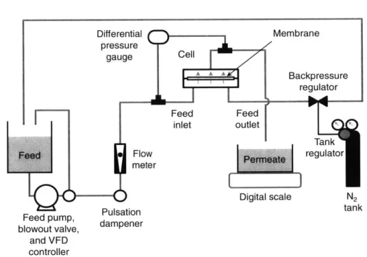
2-2 Schematic of experimental setup. . . . . 31 2-3 Flux vs. time for hexadecane-in-water emulsions stabilized by anionic SDS
(squares), nonionic Tween 80 (circles), and cationic CTAB (triangles) sur-factants in (a) dead-end batch and (b) crossflow. . . . . 35
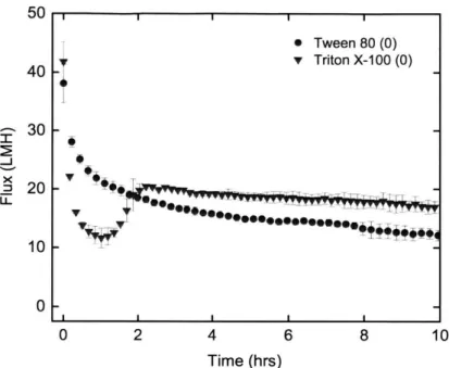
2-4 Dead-end batch filtration of Tween 80 (circles) and Triton X-100 (inverted triangles) stabilized emulsions. Data points are averages and error bars are standard deviations from two experiments for each surfactant. . . . . 36 2-5 Blocking filtration modeling for fouling of CTAB stabilized emulsion in (a)
dead-end batch and (b) crossflow. . . . . 37 2-6 Flux vs. time for D-J Basin (squares) and Barnett (circles) produced water
samples in dead-end batch filtration. Initial fluxes were 39.3 and 43.2 LMH for D-J Basin and Barnett samples, respectively. . . . . 39 3-1 Operation, surface morphology, and wettability of multifunctional membrane
for oil-water separation and in-situ degradation of organic pollutants. (a) Coated multifunctional membrane can separate oil and water without wa-ter pre-wetting by gravity and degrade organic pollutants from the wawa-ter phase upon UV irradiation. (b) Spray-coating based fabrication of the SSFT
(Si02/SF-100/FS-50/TiO 2) multifunctional membrane: Si02/SF-100 and
FS-50 (SSF) dispersions are sequentially sprayed onto the feed side of the
membrane (side facing the water to be treated) while a TiO2 (T) dispersion
is sprayed onto the permeate side of the membrane (side facing the treated water). (c) Water and oil (hexadecane) wetting behavior on uncoated mem-brane (1), SSF coated memmem-brane (2), and TiO2 coated membrane (3). . . 49
3-2 Schematic illustrations of the apparatus for gravity-driven bulk and emul-sified oil-water separation and simultaneous in-situ degradation of organic pollutants using SSFT multifunctional membrane. (a) A schematic illustra-tion of the separaillustra-tion and purificaillustra-tion apparatus used in our experiments.
(b) Contact angles for oil (hexadecane) on the feed-side of the
multifunc-tional membrane and water flux as a function of the number of passes. The number of passes corresponds to the number of times that water is added to the separation apparatus. (c) Absorbance spectra of the organic pollutant after consecutive passes at UV intensity of 1050 mW/cm2. Inset photos show water-contaminated MB dye before and MB dye-free water after 10 passes. 51
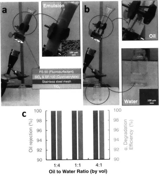
3-3 Solely gravity-driven separation of surfactant-stabilized oil-water emulsions and simultaneous in-situ degradation of organic pollutant. (a) A photograph of the apparatus for oil-water emulsions separation. Hexadecane-in-water surfactant-stabilized feed emulsion (1:1 by volume) sits above the SSFT mem-brane. Water is dyed blue (methylene blue dye as an organic pollutant). (b) Organic pollutant-free water is collected as permeate at the bottom of the apparatus while oil is retained. (c) Simultaneous emulsion oil rejection (1:4,
1:1, and 4:1 by volume hexadecane-water surfactant-stabilized feed emulsions
respectively, left blue bars) and organic pollutants (MB dye) degradation ef-ficiency (right red bars) of SSFT multifunctional membrane after one pass
under 1050 mW/cm2 UV irradiation intensity . . . . 53
3-4 Degradation of organic pollutants (MB dye) using a TiO2 coated membrane
upon UV illumination. (a) Degradation efficiency a (%) of TiO2 coated
mem-brane as a function of number of passes at constant UV light intensity. (b) Degradation efficiency a of TiO2 coated membrane as a function of UV light
intensity at constant number of pass. (c) Schematic illustration of organics degradation system and relevant parameters for degradation model (not to scale). (d) Collapsed plot of degradation efficiency a (%) as a function of X (mW1/2-s/cm). Symbols correspond to empirical data while the dashed line corresponds to the degradation model. Model yields very low maximum
(< 4%) and mean errors (1.2%). Where error bars (standard deviation of
three measurements) cannot be seen, the uncertainty is smaller than the data m arker. . . . . 54 4-1 Wetting of a substrate by liquids in water and air environments. (a) Drawing
of an oil droplet on a substrate in a water environment. (b) Work of adhesion for oil droplet attachment and removal as a function of the advancing and receding contact angles of oil underwater. (c) Drawings of a water and oil droplet on a substrate in an air environment. (d) Underwater oil contact angle as a function of the in-air oil contact angle on a substrate for contours of in-air water contact angle. . . . . 66
4-2 Scheme for creating hydrophilic/oleophobic coatings on commercial polymer membranes. (a) Fluorosilane monomer used for surface coating. (b) Typical polymer membranes are ambiphilic to water and oil. (c) Plasma treatment creates hydroxyl groups on polymer surface. (d) Triethoxysilane functional group reacts with hydroxyl groups to bond the PFA chain to the membrane surface. (e) Resulting membrane is in-air hydrophilic/oleophobic. . . . . 69
4-3 FESEM results for an (a) uncoated and (b) 5 min plasma treated membrane. 74
4-4 AFM results for (a) Uncoated and (b) 20 C coated membrane. Root mean square (RMS) roughness Rq and Wenzel roughness r are given for each sub-strate surface. . . . . 74 4-5 XPS survey scan for (a) uncoated vs. 20 C and 80 C coated membranes.
(b) Cis core level spectra resolving results for uncoated vs. 20 C and 80 C
m em branes. . . . . 75
4-6 In-air advancing contact angles for water and oil (hexadecane) on coated MF m em branes. . . . . 76
4-7 Contact angles for water, oil (hexadecane), and air on uncoated membranes (a)-(d), 200 coated membranes (e)-(h), and 80' coated membranes in an air and water environment. (d), (h), and (1) give the underwater advancing
contact angle (60*) and hysteresis (A9*) for oil on uncoated and 20 0C and
80 C coated membranes. . . . . 78
4-8 Dead-end batch filtration of SDS-stabilized hexadecane-in-water emulsions for uncoated plasma treated and coated (20', 40', 600, and 80 C)
mem-branes. (a) Flux vs. time plots (b) Flux decline and flux recovery. Error bars in (a) and (b) are standard deviation from two tests for each membrane. . . 79
4-9 Crossflow filtration of SDS and Triton X-100-stabilized hexadecane-in-water emulsions for uncoated plasma treated and 20 C coated membranes. (a) SDS-stabilized emulsion (b) Triton X-100-stabilized emulsion . . . . 80 5-1 Photo and drawing of uncoated and coated reverse osmosis (RO) membranes
and their use for oily wastewater filtration and desalination. (a) Static in-air water (dyed with Methylene Blue) and oil (hexadecane, dyed with Oil Red) contact angles on omniphilic as received RO membranes and on coated mem-branes. (b) For oily wastewater desalination, ultrafiltration (UF) pretreat-ment is typically required before desalination by RO due to oil sensitivity of the polyamide active layer. The use of coated RO membranes could obviate this pretreatment step. . . . . 85 5-2 Scheme for creating hydrophilic/oleophobic coatings on commercial polymer
membranes. (a) Fluorosilane monomer used for surface coating. (b) Typical polymer membranes are ambiphilic to water and oil. (c) Plasma treatment creates hydroxyl groups on polymer surface. (d) Triethoxysilane functional group reacts with hydroxyl groups to bond the PFA chain to the membrane surface. (e) Resulting membrane is in-air hydrophilic/oleophobic. . . . . 88 5-3 In-air contact angle results for coated and uncoated reverse osmosis
mem-branes. (a) In-air water and oil (hexadecane) contact angles for a variety of coated and uncoated (neat) reverse osmosis membranes. Membranes are listed from left-to-right in order of decreasing in-air oil contact angle and all membranes were coated with PFA-silane for 12 hrs at 50 C. Active layer compositions were polyamide (PA), polyamide-urea (PA-u), and cellulose ac-etate (CA). (b) Toray 82V advancing water and oil (hexadecane) contact angles for uncoated (0 hr) and coated RO membrane substrates. 02 plasma treatment times of 60 sec at 6.3 W of power and coating temperatures of
50 C were used for all substrates. Error bars in (a) and (b) are standard
deviations of six measurements calculated from the left and right sides of at least three droplets placed on different dry sites on the membrane surface. . 93
5-4 ATR-FTIR results for uncoated vs. coated (12 hrs at 50 C) RO membranes. The 1206 cm- 1 peak corresponds to the CF2 side chains of the PFA chain. The CF3 peak is difficult to observe because its location overlaps with other peaks from the RO membrane chemical structure. . . . . 95 5-5 XPS survey scan for (a) uncoated, 02 plasma treated, and coated (12 hrs at
50 C) RO membranes. (b) Cis core level spectra resolving results of coated
5-6 AFM results for (a) uncoated and (b) coated membrane (after 5 min EtOH bath with air drying). Root mean square (RMS) roughness Rq and Wenzel roughness r are given for each substrate surface. . . . . 96 5-7 Contact angles for oil, water, and air on uncoated membranes (a)-(d) and
coated membranes (e)-(h) in an air and water environment. (d) and (h) give the underwater advancing contact angle (0*) and hysteresis (AO*) for oil on the uncoated and coated membrane. . . . . 97 5-8 Contact angle vs. time for a hexadecane droplet on a coated RO membrane
surface indicating low PFA chain graft densities. . . . . 98 5-9 Permeability and salt passage of coated and uncoated membranes are
main-tained after coating. Error bars are standard deviation of at least two per-meability and salt passage experiments for each membrane. . . . . 99 5-10 Fouling and cleaning performance for coated vs. uncoated membranes
sub-jected to (a) 1500 mg/L SDS stabilized hexadecane-in-water emulsion, (b)
1500 mg/L Tween 80 stabilized hexadecane-in-water emulsion, (c,d) 1500 mg/L
hexadecane-in-water emulsion. Tests (a-c) were performed in dead-end flow and test (d) was performed in a crossflow setup. Initial flux for all tests was 30 2 LMH and 2 g/L NaCl desalination step is shown before foulant addition step. . . . . 101
B-1 Twill Dutch weave mesh: (a) SEM image of mesh, (b) Digital visualization of mesh from http://www.spoerl.de/en/wp-content/uploads/sites/2/
2014/08/0008_big-458x300.jpg. ... ... 107
B-2 Static contact angles of oil (hexadecane) and water on (a) uncoated glass and
(b-d) coated glass. . . . . 110
B-3 Degradation experiment repeatability and TiO2 robustness as shown by
iden-tical degradation efficiency and MB absorbance for 5 experimental runs. . . 111
B-4 Concentration of MB Dye (red circles) and degradation efficiency per two passes (green squares) as a function of the number of passes using TiO2 coated
membranes at constant UV light intensity (I = 372 mW/cm2). Dotted lines connecting data markers were included to guide the eye. Uncertainties for all data are smaller than the data markers. . . . . 112 B-5 Thermogravimetric analysis (TGA) data of water, hexadecane, and feed
so-lution permeate after 10 passes with high oil rejection. . . . . 112 B-6 Separation of surfactant-stabilized oil-water emulsions and simultaneous
or-ganics degradation of MB Dye present in the water phase. (a, c, and e) Optical microscopy images of 1:4, 1:1, and 4:1 (hexadecane:water by volume) emulsions, respectively. 1:4 and 1:1 emulsions are oil-in-water and 4:1 emul-sion is water-in-oil. (b, d, and e) Droplet size distributions of 1:4, 1:1, and 4:1 emulsions, respectively. (g, h, and i) Optical microscopy images of 1:4,
1:1, and 4:1 permeates, respectively. . . . . 113 B-7 Volume-based droplet size distributions of permeate from (a) 1:4, (b) 1:1,
(c) 4:1 surfactant stabilized oil-water emulsions with one pass. 1:4 and 1:1 emulsions are oil-in-water (SDS stabilized) and 4:1 is a water-in-oil emulsion
(Span80 stabilized). . . . . 114
List of Tables
2.1 Time-flux and time-flux-volume set of equations for fouling mechanism anal-ysis where J* is steady state flux, 9 = J-J*, and J = J(t). . . . . 26
2.2 Surfactant properties obtained from DOW, and Sigma-Aldrich product lit-erature and Needs [1]. . . . . 28 2.3 Produced water and model oil-water emulsion characterization. pH values
have a t 0.01 accuracy and TOC measurements have a 1.5% accuracy. . 29
2.4 Initial flux Jo, steady state flux J*, and specific volume v (L/m2) results for model emulsion fouling runs. . . . . 35 2.5 Statistics for blocking law fitting of model oil-water emulsions. Average
ab-solute percentage deviation AAPD, goodness of fit R2 values, and fitting parameter K are averaged for two runs and provided for each fouling mech-anism. Standard deviation for AAPD is provided. Mechanism statistics with lowest AAPD is bolded for ease of reference. Units for fitting parameters are: complete K2 (hr-1), standard K1.5 (m/L0 5-hro.5), partial K (m2/L), and
cake K
o
(m 4-hr/L2). . . . . 38 2.6 Statistics for blocking law fitting of produced water. Average absoluteper-centage deviation AAPD, goodness of fit R2 values, and fitting parameter K are given for each fouling mechanism. Mechanism statistics with lowest
AAPD is bolded for ease of reference. Units for fitting parameters are:
com-plete K2 (hr-1), standard K1.5 (m/L0 5-hro.5), partial K, (m2/L), and cake
K o
(m 4-hr/L2). . . . .40
5.1 Operating conditions for this study . . . . 89 5.2 Solvent polarity causes chain reconstruction on coated membranes . . . . . 94
B.1 Effect of fixed UV intensity and varying passes on degradation efficiency . . 109 B.2 Effect of varying UV intensity and fixed passes on degradation efficiency . . 109
Nomenclature
Roman symbols Units
As wetted surface area of membrane m2
Am membrane area m2
AAPD average absolute percentage deviation %
C concentration mol/L, mg/L, or mg/mL d droplet diameter pm D fiber diameter pm Dh hydraulic diameter m h pore height Jm I UV light irradiance mW/cm2 J or J, permeate flux L/m2-hr or m/s
kads adsorption constant for organic pollutant L/mg
kapp applied rate constant s-1
kp photocatalytic rate constant mg/L-s
M molecular weight g/mol
P hydraulic pressure kPa or bar
t time s
Vr reactor volume m3
w pore width ptm
X collapsed variable for analytical degradation model mW1/2-s/cm
Greek symbols Units
a degradation efficiency %
/3 figure of merit for flow through photocatalytic system cm/mW1/2-s
surface tension or surface energy mN/m or mJ/m2
E model error %
E
dimensionless scaled fluxIT osmotic pressure bar
p density kg/L a- standard deviation Subscripts 0 1 1.5 2 A a ad h 0 R s t w
initial state or cake filtration
partial blocking internal blocking complete blocking advancing air adhesion hydrophilic oil receding substrate function of time water
Superscripts
steady state or apparent contact angle
Abbreviations CA contact angle HB hydrophobic HL hydrophilic MF microfiltration OB oleophobic OL oleophilic PFA perfluoroalkyl RO reverse osmosis SHL superhydrophilic SOB superoleophobic SSF SiO2/SF-100/FS-50 SSFT SiO2/SF-100/FS-50/TiO 2 UF ultrafiltration UV ultraviolet
Chapter 1
Introduction
The separation of oil from water is a crucial wastewater treatment step in many industries including oil and gas, metalworking, textile and paper, food processing streams, cosmetics, and pharmaceuticals [2]. Oil/water separation is also required for treating oil spills which can cause significant environmental damage if not treated effectively and quickly [3]. An oily wastewater of emerging concern is produced water, a waste stream from hydraulic fracturing processes.
1.1
Produced water
Oil and gas companies produce between seven and fifty barrels of produced water for every barrel of oil. This amounts to upwards of 2.4 billion US gallons of wastewater produced per day worldwide which much be treated or properly disposed [4]. Among the many contami-nants in produced water [5], these wastewaters contain small, hard-to-separate (emulsified) oil droplets which must be removed by well operators when recycling or disposing of these waters. To do so, companies usually rely on chemical coagulation, a costly and often ineffective method of emulsion removal that requires expensive and hazardous chemicals which produce a useless sludge. The sludge must be disposed, typically by trucking to an off-site dumping reservoir or an open pit where natural water resources can become con-taminated [4]. Due to the high cost of water treatment, wastewater is often injected into disposal wells rather than treated, resulting in contamination, high water consumption, and even seismic activity [6, 7]. As such, the industry has come under increasing political and economic pressure to more efficiently manage the billions of gallons of produced water from their oil and gas extraction activities.
1.2
Oil/water separation technologies
There are many technologies available for treatment of oily wastewaters. The concentration and size of dispersed oil in these waters typically dictates which treatment technology is used. Oil/water mixtures can be classified into three categories based on oil droplet diameter
d: free mixtures d > 150 pm, dispersions 20 < d < 150
pin,
and emulsions d < 20 ym [2]. Emulsions can be either oil-in-water (oil as the dispersed phase, water as the continuous phase) or water-in-oil (water as the dispersed phase, oil as the continuous phase) depending on surfactant type, volumes of both phases, temperature, pH, and other factors [8, 9]. Inthis thesis, we focus on water-in-oil emulsions due to their prevalence in produced water and other industrial oily wastewaters [2, 5, 10, 11].
Gravity-based separation technologies, such as lamella clarifiers, are often used as pri-mary treatment for oily wastewaters because they are effective for free and dispersed oil/water mixtures. This is because droplets with a diameter of > 25 Am have faster settling velocities, as predicted by Stokes' law, than droplets < 10 Am [12]. The retentate streams from these treatment systems, therefore, typically contain oil in an emulsified form. Emulsified oil can be stabilized by surfactants, polymers, asphaltenes, or other solids which accumulate at the oil-water interface [8, 13].
Several technologies exist for treatment of the remaining emulsified oil. These technolo-gies include chemical coagulation, dissolved air filtration, hydrocyclones, media filtration, and polymeric or ceramic membranes. Operators must balance four criteria when choosing a technology to use: power requirements, footprint and weight, oil and particulate rejection, and cost.
1.2.1 Chemical coagulation
Chemical coagulation is the addition of highly charged metal cations and polymers to re-duce the repulsive double layer which surrounds each droplet, reducing the electrostatic repulsive energy barrier consequently reducing coalescence times. This process, however, is
highly susceptible to variable influent quality, requires time consuming jar testing for careful
chemical selection, is ineffective for small droplets, has a large footprint, and produces large volumes of sludge [2]. Although more responsive to variable influent quality and operable at smaller system footprints, electrocoagulation/flocculation, like chemical coagulation, is ineffective for small droplets and also creates large volumes of sludge [4, 14].
1.2.2 Dissolved air flotation
Dissolved air flotation (DAF) uses gas bubbles to remove suspended particles that are difficult to separate through sedimentation. DAF suffers from high system complexity as well as high operation and maintenance costs [4, 5]. DAF systems are also ineffective at removing particles and oil droplets smaller than 10 Am [5].
1.2.3 Hydrocyclones
Hydrocyclones separate solids and oils from water based on density differences between phases. They are robust, mobile, and are operable with small system footprints relative to chemical coagulation and DAF, but suffer from high capital and energy costs [4, 5]. Furthermore, hydrocyclones are ineffective at removing particles and oil droplets smaller than 10 jm [5].
1.2.4 Media filtration
Media filtration uses various types of media such as walnut shell, gravel, or anthracite to separate particles by adsorption and steric exclusion. While media filtration is an efficient way to remove free and dispersed oil and grease, it is ineffective at removal of sub-micron oil droplets and particulates and suffers from high maintenance costs [5].
1.2.5
Membrane filtration
Polymeric/ceramic microfiltration (MF) and ultrafiltration (UF) are applicable to chal-lenging wastewaters and are able to consistently separate small emulsified oil droplets in addition to other suspended solids. Relative to other technologies, they use less energy and are highly modular and mobile [4]. As a result of these advantages, MF and UF treat-ment systems have emerged as the preferred method for oily wastewater treattreat-ment and desalination pretreatment [2, 5, 10, 11, 15].
1.3
Membrane technologies
In addition to separation of emulsified oil from water, many produced water streams also require desalination for reclamation or reuse. For these very salty feedwaters, thermal technologies are frequently used although reverse osmosis (RO) membrane technologies are predicted to energetically outperform them [16] and may eventually be used for these highly saline feed waters as well. To summarize, membrane technologies are supplanting other es-tablished technologies not only for oil/water separation but for salt separation (desalination) as well.
One of the main impediments to using RO for the desalination of oily wastewaters is that RO membranes have an extremely low tolerance for oil in the feed stream [17]. Organic fouling by oil and grease can cause irreversible and severe decreases in permeability along with possible degradation of the membrane. Organic emulsions, in particular, can form a film on the membrane surface and must be removed in pretreatment. For their RO membranes, DOW recommends an extraordinarily low maximum contaminant level of 0.1
mg/L of oil in the feed stream [18]. DOW reports that oil fouling is especially difficult to
remove from a membrane surface once it has occurred.
In addition to RO, MF and UF membranes are also severely affected by free, dispersed, and emulsified oil fouling [2, 19-22]. Because membrane systems are so effective at treatment and desalination, however, improving their fouling resistance to organic foulants such as oil has been an area of great academic focus. For decades, researchers have made efforts to develop anti-fouling membranes by increasing the hydrophilicity of membrane surfaces
[23-25]. While these investigations have yielded significant gains in membrane resistance to
fouling, researchers continue to find new ways to push the limits of anti-fouling performance. Recently, exciting new surfaces which are simultaneously hydrophilic and oleophobic in-air have been reported in the literature [26-31]. The properties which endow these surfaces with their unique in-air wettability have been applied to porous materials and membranes for free and emulsified oil/water separation with reported high rejection and anti-fouling
performance [26, 27, 29, 30, 32-34].
For instance, Kota et al. used a hybrid coating comprised of hydrophilic and hydropho-bic/oleophobic (omniphobic) fluorocarbon moieties to create a membrane which allows for water passage during filtration of oil-in-water and water-in-oil emulsions and even bulk oil-water mixtures [26]. This filter, which was hydrophilic and oleophobic in an air envi-ronment, demonstrated high oil rejection and high fluxes with little fouling in steady state. Another research group added an omniphobic fluorocarbon moiety during the production of a polymeric membrane to create a filter which was also hydrophilic and oleophobic in an air environment. Dead-end and crossflow experiments were used to show that the novel membranes which contained the fluorocarbon compounds fouled less during oil-water emul-sion filtration than benchmark membranes without the compound [31]. These are exciting
developments which are investigated in the latter chapters of this thesis.
1.4
Thesis aims
In this thesis, we contribute to the field of oil/water separation through several studies: In Ch. 2, we seek to better understand fouling by oil-in-water emulsions on conventional polymeric ultrafiltration membranes. We investigate the decrease in water production over time using model and actual produced water samples with varying solution zeta potentials and make meaningful recommendations to operators based on our observations.
In Ch. 3, we develop a robust multifunctional membrane which can in one step degrade organic pollutants and separate bulk and surfactant-stabilized oil/water mixtures with high fluxes, oil rejection, and degradation efficiencies.
Finally in Ch. 4 and Ch. 5, we investigate the potential of novel in-air hydrophilic and oleophobic MF and RO membranes for their anti-oil fouling performance relative to conventional hydrophilic and oleophilic membranes. Contrary to claims in literature of superior filtration performance, we find that ,in-air oleophobicity does not aid in underwater anti-fouling due to surface reconstruction of mobile perfluoroalkyl chains in the presence of water. Based on these observations, we discuss opportunities for future research on oil anti-fouling membranes using fluorinated moieties.
Overall, this thesis contributes to the field of oil/water separation by better under-standing fouling mechanisms on conventional membranes, by making advances in filtration and purification technology via novel multifunctional membranes, and by investigating the potential of membranes with unique in-air wettability for enhanced underwater oil filtration.
Chapter 2
Effect of oil-in-water emulsion
surfactant charge on ultrafiltration
membrane fouling in dead-end and
crossflow filtration
Chapter abstract
In this chapter, we assess the role that surfactant head charge plays during surfactant-stabilized oil-in-water emulsion fouling of polymer ultrafiltration membranes. The extent of fouling was determined by steady state flux in constant pressure dead-end batch and crossflow filtration. Emulsions are prepared with anionic (SDS), nonionic (Tween 80), and cationic (CTAB) surfactants which have droplet size distributions and concentrations representative of oily wastewater obtained from hydraulic fracturing operations. In dead-end batch filtration, cationic and anionic emulsions result in similar fouling while nonionic emulsions are observed to destabilize easily. In crossflow filtration, cationic emulsions are observed to result in the lowest steady state flux followed by nonionic and finally anionic emulsions. These results suggest that droplet-droplet electrostatic repulsion dominates fouling in dead-end batch filtration while droplet-membrane electrostatic interactions are more relevant in crossflow operations. We also filter two produced water samples with nearly neutral zeta potentials in dead-end batch mode and observe that fouling was most similar to anionic and cationic (not nonionic) emulsions, implying that oily wastewaters in the produced water space may be stabilized by steric rather than electrostatic repulsion. Applying fouling blocking models, we may infer that nonionic emulsions form cakes while anionic and cationic surfactants completely and partially block membrane pores indicative of a thin coating of oil on the membrane surface. On the basis of steady state flux results, we recommend that anionic surfactants be used to stabilize emulsions treated by crossflow filtration and nonionic surfactants be used to stabilize emulsions treated by dead-end batch filtration.
2.1
Introduction
Oil-water separation is a crucial step in the remediation of wastewater from many industries including oil & gas, metalworking, textile and paper, cosmetics, and food [2]. Oil-in-water mixtures can be classified into three categories based on oil droplet diameter d: free mix-tures d > 150 pim, dispersions 20 < d < 150 pm, and emulsions d < 20 pLm. Efficient separators for emulsions, in particular, are of interest because conventional technologies such as gravity-based separation, heating/cooling, and chemical coagulation are more ef-fective for free mixtures and dispersions and are too complex, costly, or simply unable to effectively treat emulsions [2, 5]. Streams containing oil-water emulsions must also be nearly oil free if they are to be desalinated using a membrane-based process. The DOW Chemical Company, for instance, recommends less than 0.1 part per million of oil and grease for their FILMTEC line of reverse osmosis membranes [18]. For emulsion treatment, ultrafiltration
(UF) and microfiltration (MF) are finding increasingly widespread use due to their low cost
and energy efficiency [10, 35].
While membrane systems are considered to be the benchmark in emulsion treatment, an outstanding issue is the deleterious effect of oil fouling on the membranes over time. During constant pressure filtration, fouling causes a decline in flux over time resulting in reduced permeate production. This leads to system oversizing to compensate for the permeate lost by fouling. During constant flux filtration, fouling causes an increase in applied trans-membrane pressure over time resulting in increased energy costs. The rise in pressure leads to increased energy consumption. In both constant pressure and flux filtration, mechanical cleaning, backwashing, or chemically enhanced cleaning methods are used to restore membrane permeability. The extent of permeability restoration also declines over time due to irreversible fouling [36, 37]. In sum, fouling is important to understand and minimize as it increases plant capital and operating expenditures.
An oily wastewater of emerging concern is the effluent from hydraulic fracturing opera-tions known as produced water [5]. Produced waters can contain up to 1500 mg/L of total organic carbon and up to 60 mg/L of oil/grease [5], much of which is in an emulsified form. We use these wastewaters as the model foulant in this chapter.
Emulsions are kept stable for long periods of time by an emulsifier or surfactant. These agents keep oil droplets from coalescing by electrostatic or steric repulsion and by reducing the liquid-liquid interfacial surface tension. These agents are sometimes added intention-ally to aid in hydrocarbon extraction but may also enter the feeds naturintention-ally during the extraction process. Typical emulsifiers found in produced water include paraffins, metallic salts, organic acids, resins, colloidal silts and clay, asphaltenes, and polymers [13]. These emulsifiers are able to stabilize oil droplets by predominantly steric rather than electrostatic repulsion. Other types of stabilizers are surfactants, which can be categorized according to the charge of their hydrophilic head: anionic (-), cationic (+), nonionic (0), and amphoteric ( ) [8]. The nature of membrane fouling by anionic, nonionic, and cationic surfactants has
been investigated in the literature and the shape and charge of the surfactant head play an important role in fouling [38, 39].
MF and UF fouling by oil-water emulsions is a complex process affected by oil and surfactant concentration, oil droplet size, emulsion stability, and operating conditions [19, 20, 40-44]. Although explored to a lesser extent, surfactant and membrane zeta potentials also play a significant role during fouling and irreversible permeability loss. In an aqueous environment of neutral pH, polymer and ceramic membranes have a negative zeta potential (a proxy for surface potential) while surfactant potentials are primarily determined by the valence of the head charge. During filtration, surfactant and membrane potentials result in droplet-droplet and droplet-membrane electrostatic interactions which we find to be of crucial importance in fouling severity. Lu et al. [43] found that diesel and crude-oil emulsions stabilized by a nonionic surfactant (polyoxyethylenesorbitan monooleate, Tween
80) resulted in the least irreversible fouling for cycles of dead-end batch filtration and water
rinsing using ceramic ultrafiltration membranes. The extent of irreversible fouling increased for the cationic (cetyltrimethylammonium bromide, CTAB) surfactant and was greatest for the anionic surfactant (sodium dodecyl benzenesulfonate, SDBS).
In this chapter we determined the effect of surfactant charge on the fouling severity in the filtration of oil-water emulsions using a polymer (polyacrylonitrile) ultrafiltration membrane in both dead-end batch and crossflow filtration modes. We studied two filtration modes to compare fouling in the different applications where each mode is used. There are
two main differences between both modes of filtration. Firstly, in dead-end batch, feedwater flows perpendicular to the membrane surface while it flows parallel to the membrane surface in crossflow. More importantly, the emulsion concentration rises in the cell over time in dead-end batch filtration while it stays relatively constant in crossflow filtration. While dead-end batch filtration tests are easier to perform in the laboratory and, thus, are often used by researchers to characterize membrane performance or assess the fouling potential of certain feedwaters, these tests are also representative of dead-end hollow fiber filtration, which are often used to achieve high permeate recoveries during treatment [22]. Therefore, our results for dead-end batch tests may be relevant to these hollow fiber systems. Crossflow filtration systems are also widely used and experience less fouling compared to dead-end systems [36].
We characterized six samples of produced water, our model foulant, to assess oil con-centration, suspended droplet size distribution, pH, and zeta potential. We prepared three model oil-in-water emulsions using anionic (sodium dodecyl sulfate, SDS), nonionic (Tween
80), and cationic (CTAB) surfactants which were representative of produced water samples
based on oil concentration and volume-based droplet size distribution. We investigated the extent of flux decline in constant pressure dead-end batch and crossflow filtration using these model emulsions. We found that the extent of fouling differs greatly as a function of surfactant charge and filtration mode (dead-end batch vs. crossflow). We also filtered two produced water samples in dead-end batch mode and results are compared to model emul-sions. To infer which fouling mechanisms may have prevailed during fouling, we applied classic blocking filtration laws considering both fouling deposition and removal to the flux decline curves.
2.2
Blocking law theory for constant pressure filtration
Fouling refers to the decrease in water production due to the increase of hydraulic resistance in membrane systems over time. It is a complex, kinetic process determined by the rates of particle deposition and removal from the membrane surface and pores. Regarding particle deposition, four mechanisms exist for fouling of porous membranes by suspended solids
during filtration: complete pore blocking, internal pore blocking, partial pore blocking, and cake filtration. These physical mechanisms were first described by Hermans and Bred6e [45] and compiled and expanded by Hermia for dead-end flow applications [46]. The models can be expressed in terms of permeate flux J as a function of time t, a proportionality constant
Ka, and an exponent n which denotes the mode of fouling:
d J
= Kn J3-n (2.1)
dt
The constant Kn is often found by curve fitting and the fouling modes are given by n = 2 for complete pore blocking, n = 1.5 for internal pore blocking,
n
= 1 for partial poreblocking, and n = 0 for cake filtration. Complete pore blocking occurs when large particles
in solution block the entirety of a pore mouth preventing permeate from flowing through the pore. Internal pore blocking refers to the decrease of the effective radius of membrane pores as smaller particles enter the mouths and adsorb onto pore walls. Partial pore blocking occurs when a single or multiple particles partially cover each pore. Cake filtration occurs when a porous layer, or cake, of particles forms and increases in thickness on the membrane surface acting as an in-series hydraulic resistance.
While useful and widely used, the models given by Eq. 2.1 only consider the deposition portion of the fouling process. Without a removal term, the final flux during filtration would mathematically be zero for long times (t -- oc) as foulant continues to deposit onto the membrane surface. In order to study these models, many researchers use pressurized dead-end flow filtration cells without stirring in an effort to minimize particle removal.
To infer which fouling mechanism may have been most prevalent during flux decline experiments, we use equations developed by Field et al. [40, 47]. These equations include a final flux term that effectively allows for the consideration of foulant removal during filtration. There are two sets of equations, the time-flux and time-flux-volume, which we summarize in Table 2.1. To use the equations, we assume that the particles contributing to flux decline do not coalesce (where two or more suspended oil drops join to form a single droplet) at the membrane surface or within a cake and that their removal rate is constant with respect to time. We assume that foulant removal from the membrane surface occurs
Table 2.1: Time-flux and time-flux-volume set of equations for fouling mechanism analysis where J* is steady state flux, 0 = JO_J* , and J = J(t).
Fouling mechanism n Time-flux set Time-flux-volume set Description
Complete blocking 2 In Ie = K2t (2.3) Jo - J = K2(v - J*t) (2.4) Particles reaching the membrane entirely seal a pore.
Internal blocking 1.5 J-0'5 - J6-0'5 = K,. t (2.5) JO.5 - 5 = K1.s(v - J*t) (2.6) Pore volume decreases proportionally to Ril permeate volume. Pores are constant
di-ameter and length.
Partial blocking 1 1n = Kit (2.7) In = K,(v -Jt) (2.8) Incremental blocked surface area is pro-portional to unblocked surface area. Cake filtration 0 In - J' = Kot (2.9) - = K.(? - J*t) (2.10) Flux decreases with an in-series hydraulic
resistance proportional to permeate mass.
either through emulsion flocculation and creaming [8] and/or by inertial lift (in crossflow filtration). Note that the complete, partial, and cake blocking laws allow for individual particle deformation [46].
We use both sets of equations in Table 2.1 as follows: the time t, specific permeate volume v, flux J, initial flux Jo, and steady state flux J* from each fouling test are used with the time-flux-volume set of equations (Eqs. 2.4, 2.6, 2.8, 2.10 from Table 2.1) to find
K and the coefficient of determination R2 through a linear fit. We then use each obtained
blocking coefficient K to model the flux decline as a function of t, Jo, and J* using the time-flux set of equations (Eqs. 2.3, 2.5, 2.7, 2.9 from Table 2.1). Because many of the
R2 values are near unity, we use the average absolute percentage deviation between flux data and predicted flux from each model to determine goodness of fit and assess which mechanism may have predominated during fouling. Average absolute percentage deviation,
AAPD, is determined by:
AAPD = Z 1 -hrnodel 100 (2.2)
m
Ji, datawhere m is the number of data points in the time series and i refers to the ith element in the series.
We use the time-flux-volume set of equations for linear regression analysis because we found that use of these equations rather than the time-flux set significantly reduced noise in the later stages of filtration as J approached J* during curve fitting. The reduction of noise allowed for more accurate curve fitting, providing K, values which were used to calculate
2.3
Experimental procedures
2.3.1
Preparation of oil-in-water emulsions
Three oil-in-water emulsions were prepared for each fouling test using three separate surfac-tants (Sigma Aldrich): sodium dodecyl sulfate (SDS, anionic), cetyl trimethylammonium bromide (CTAB, cationic), and polyoxyethylenesorbitan monooleate (Tween 80, nonionic). Triton X-100 (Sigma Aldrich) was also used for a series of dead-end batch tests. Hexadecane
(99.9%, Sigma Aldrich) (yLv 27.5 mN/m) was used as the model oil due its low surface
tension, consistent chemical composition, and use in other studies [44].
Each surfactant stabilized oil-in-water emulsion was prepared using a 10:1 oil to surfac-tant ratio by weight with DI water to give 625 mg of oil and surfacsurfac-tant per liter of solution. For dead-end batch tests, 0.227 g of hexadecane and 0.023 g of surfactant was added to 400 mL of deionized water (DI) and sheared in a blender (Waring) for 5 minutes. After the gas-liquid foam resulting from the blending destabilized over roughly 30 minutes, 300 mL of this mixture was added to the dead-end cell. For crossflow tests, 7.737 g of hexadecane
(99.9%, Sigma Aldrich) and 0.774 g of surfactant were added to 400 mL of deionized water
and sheared in a blender for 5 minutes. Of this mixture, 300 mL was added to the system feed tank after the gas-liquid foam resulting from the blending destabilized over roughly 30 minutes. All prepared emulsions were visibly stable for at least a 20 hour period.
Table 2.2 gives for each surfactant its charge, molecular weight M, critical micelle con-centration (CMC), hydrophilic lipophilic balance (HLB), the molecular weight of the hy-drophilic portion of the surfactant Mh, and surfactant chemical structure. We calculate
Mh = 0.05 - M - HLB assuming Griffin's method [9].
Surfactant concentrations in this study were 57.5 mg/L, meaning that SDS and CTAB concentrations are below their CMC while Tween 80 was above the CMC by a factor of 4.4. In general nonionic surfactants have a much lower CMC than ionic surfactants, making it challenging to prepare a concentrated nonionic surfactant-stabilized oil-in-water emulsion with surfactant concentrations below the CMC. We therefore include an additional nonionic surfactant, Triton X-100, for dead-end batch tests to compare performance against Tween 80.
Table 2.2: Surfactant properties obtained from DOW, and Sigma-Aldrich product literature and Needs [1].
Surfactant Charge M (Da) CMC (mg/L) HLB Mh (Da) Structure
0 0 SDS Anionic 288.4 2010.8 to 2884.0 40.0 576.8 Na 0 04 H 0 OH - w+x+y+z=20 Tween 80 Nonionic 1310.0 13.0 to 15.0 15.0 982.5 Of__ fH Triton X-100 Nonionic 625.0 189.0 13.4 418.8 CTAB Cationic 364.5 335.3 to 364.5 10.0 182.3
Br-2.3.2 Produced water and model emulsion characterization
Six produced water samples were obtained from Gradiant Corp. from different hydraulic fracturing sites across the United States. All samples were collected at the outlet of a preliminary gravity-based oil/water separator used to separate free and dispersed oil. The samples were characterized as received.
Droplet size distributions in the prepared model emulsions and produced wastewater samples are shown in Fig. 2-1. They were measured using a dynamic light scattering device (ZetaSizer, Malvern) using the refractive index of hexadecane (RI = 1.434). Log-normal Gaussian curves were fit to the measured data points using Excel Data Solver and the mean and standard deviation for each peak is given. For the Bakersfield and Barnett samples, the three peaks with the greatest amplitude are reported.
Zeta potential of the model emulsions and wastewater samples were calculated from the electrophoretic mobility measured using a zeta potential analyzer (ZetaPALS, Brookhaven Instruments Corporation) and averaged over 3 runs, applying between 2.5 and 5 volts and 2 to 5 hZ for 50 cycles each run. Produced water samples were diluted with DI water until sample conductivity was below 30 mS/cm before zeta potential measurement.
Conductivity for each sample is measured using a conductivity meter (HQ440d, Hach) and pH is measured using a pH meter (sympHony, VWR).
![Table 2.2: Surfactant properties obtained from DOW, and Sigma-Aldrich product literature and Needs [1].](https://thumb-eu.123doks.com/thumbv2/123doknet/13886069.447122/29.917.133.735.160.449/table-surfactant-properties-obtained-sigma-aldrich-product-literature.webp)