Processing and Characterization of a New Biodegradable
Composite Made of a PHB/V Matrix and Regenerated
Cellulosic Fibers
Ch. Bourban, 1'2 E. Karamuk, 1 M. J. de Fondaumi~re, 1 K. Ruttieux, 1 J. Mayer, l and
E. Wintermantel I
In this study, a biodegradable composite consisting of a degradable continuous cellulosic fiber and a degradable polymer matrix--poly(3-hydroxybutyrate)-co-poly(3-hydroxyvalerate (PHB/V with 19% HV)--was developed. The composite was processed by impregnating the cellulosic fibers on-line with PHB/V powder in a fluidization chamber. The impregnated roving was then filament wound on a plate and hot-pressed. The resulting unidirectional composite plates were mechani- cally tested and optically characterized by SEM. The fiber content was 9.9 + 0.9 vol% by vol- umetric determination. The fiber content predicted by the mle of mixture for unidirectional com- posites was 13.8 • 1.4 vol%. Optical characterization showed that the fiber distribution was homogeneous and a satisfactory wetting of the fibers by the matrix was achieved. Using a blower to remove excess matrix powder during processing increased the fiber content to 26.5 • 3.3 vol % (volumetric) or 30.0 + 0.4 vol% (rule of mixture). The tensile strength of the composite parallel to the fiber direction was 128 + 12 MPa (10 vol% fiber) up to 278 ___ 48 MPa (26.5 vol% fiber), compared to 20 MPa for the PHB/V matrix. The Young's modulus was 5.8 + 0.5 GPa (10 vol% fiber) and reached 11.4 + 0.14 GPa (26.5 vol% fiber), versus 1 GPa for the matrix.
KEY WORDS: Processing; biodegradable composite; biodegradable polymers; PHB/V; regenerated cellu- losic fiber.
I N T R O D U C T I O N
The use of biodegradable polymers contributes to reduce actual waste and environmental problems, but these materials still suffer from high production costs. Reinforcement with biodegradable cellulosic fibers would improve the mechanical properties of the bio- polymers and increase their range of applications, and thus, such a composite will be worth its higher price and will be totally biodegradable. This type of composites undergoes the compound's polar incompatibility in- duced by the hydrophylic (polar) character of cellulose
t ETH Zurich, Chair of Biocompatible Materials Science and Engi- neering, Schlieren, Switzerland.
2To whom correspondence should be addressed at ETH-BWB, Wagi- strasse 23, CH-8952 Schlieren, Switzerland.
and the hydrophobic (nonpolar) one of the synthetic polymers [1, 2]. Potential applications are seen in the field of energy and impact absorption, where a weak interfacial shear strength is advantageous (sport protec- tion articles, bicycle helmets [3], bumpers for light cars). Increased composite interfacial shear strength would al- low its application for structural elements and eventu- ally allow it to compete, after redimensioning of the parts, with high-performance composites: internal parts of vehicles [4], sport articles, transport containers, and special packaging. Other specialty domains are medical applications [5, 6] and as osteosynthesis plates (e.g., Refs. 7 and 8). A previous study showed poor homo- geneity of the fiber distribution in the unidirectional composite and poor fiber-matrix adhesion [3]. In this study, a processing method for a totally biodegradable composite consisting of a poly(3-hydroxybutyrate)-co-
159
160 Bourban et al.
poly(3-hydroxyvalerate) polymer matrix (PHB/V) and of a high-crystalline regenerated cellulosic fiber is pro- posed. Both matrix and fibers are manufactured from renewable resources, and both undergo sustainable de- velopment. A filament winding process, which can be highly automated, was used. Cellulosic fibers are inten- sively investigated as fiber or reinforcement material for conventional thermoplastics [4, 9-15] or even for PHB or PHB/V [2, 16]. In this work, regenerated fibers are used instead of native fibers. The proposed composite degrades biologically in the presence of bacteria or fungi [17, 18]. PHB/V degradation occurs mainly through en- zymatic hydrolysis, as simple hydrolysis in water is very slow [19, 20].
E X P E R I M E N T A L
Materials
The cellulosic fiber was regenerated and assembled in rovings of 1000 or 500 filaments. While the mean filament diameter was 12.4 #m, scanning electron mi- croscopy measurements showed that the standard devia- tion of the undried filament diameter was +0.58/~m (n = 66), due to the elliptical shape of the filament cross section. The surface was not treated. Fiber density was 1.52 g/cm 3 and crystallinity was about 60% (WAXS measurement). Tensile strength and elastic modulus of the used cellulosic fiber were 1400 MPa and about 36 GPa, respectively. Numerous hydroxyl groups are re- sponsible for the hydrophilic behavior of cellulose.
The PHB/V (Biopol; [21]) copolymer used con- tained 19.1% hydroxyvalerate (HV). The density of hot-
pressed plates, measured in a water bath, was 1.2196 + 0.0005 g/cm 3 (1.25 g/cm 3 for injection-molded samples and 0.28 g/cm 3 for powder [22]). The modulus of elas- ticity of samples cut in the plates was 1 GPa, and the tensile strength 20 MPa [3]. The melting temperature is 151 ~ It is a thermoplastic polyester with a mainly al- iphatic character. The high HV content is expected to give the copolymer a suitable elongation at break (eB = 27%) to match the required elongation at break for a matrix in a composite: 6B(Matrix) ~> 3 EB(Fiber) [23].
Methods
Processing
The composite was manufactured on-line with the following realized processing unit (Fig. 1).
(1) The first module is the fluidization chamber (1), where the roving is impregnated at room temperature with PHB/V powder (particle diameter of 600 nm). A six-blade propeller, optimized for this application, has a diameter of 25 cm and is spun close to the bottom of a cylindrical chamber (17-cm height and 29-cm diame- ter) at 310 rotation/min, so that PHB/V powder fills the whole chamber volume. The density of the powder in the fluidization chamber is between 16 and 33 g/L. The powder particles stick to the roving due to electrostatic forces.
(2) A blower is used to remove the superfluous bio- polymer powder in order to increase the fiber-to-powder ratio. The blower had a propeller diameter of 6 cm and the voltage can be varied between 0 and 12 V.
(3) Subsequently, the powder is sintered onto the roving in an 80-cm-long heat channel (3), where the ten~perature reaches 270~ in the middle (retention time,
Fig. 1. The on-line manufacturing process of the biodegradable composite: a cellulose roving is
impregnated with powder matrix in a fluidization chamber (1). The fiber content is increased by removing superfluous powder with a blower (2). The biopolymer powder is then fixed to the fiber in a heat channel (3) and the filaments are wound on a plate by a winding machine (4).
4 s). Since winding fibers on a plate result in discontin- uous speed, the roving is driven through a compensation section, located between the sintering and the winding modules.
(4) The winding machine pulls the preimpregnated roving through the process unit at a speed of ca. 20 cm/s and winds the impregnated roving on a plate with the dimensions 30 x 30 x 2 cm. One border of the plate is mounted with springs which are compressed by screws during the winding process. The screws are then re- leased to stretch the filaments on the plate. Winding at different angles and shapes is possible.
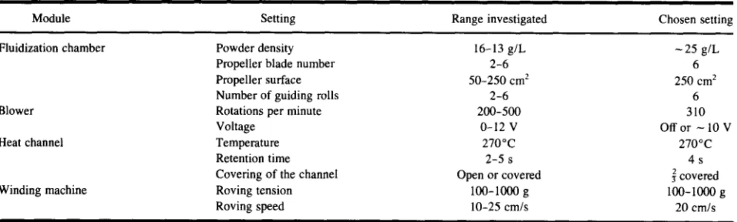
Table I shows the different process parameters. The settings were optimized in preliminary tests. The pre- pregs were then hot-pressed according to the cycle de- scribed in Fig. 2.
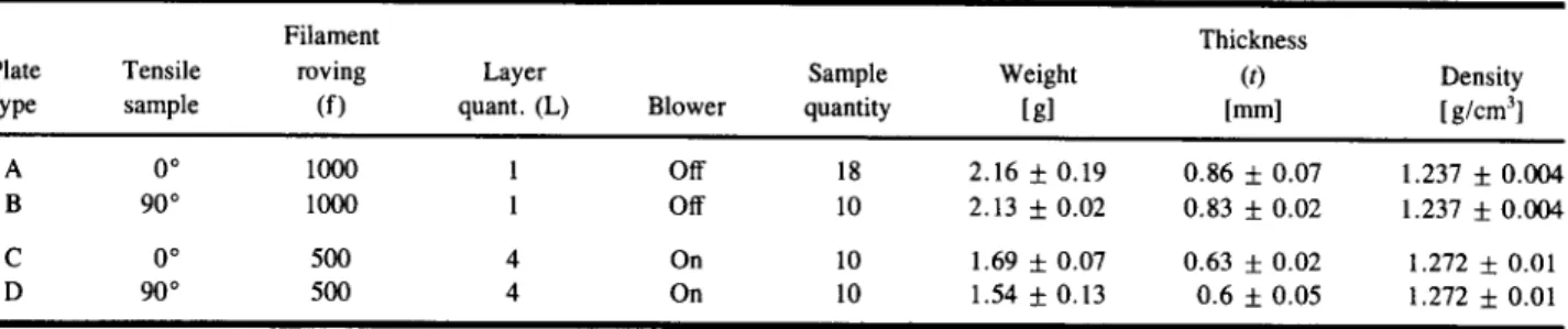
Two types of unidirectional plates were manufac- tured (Table II). Sample types A and B were processed into a single layer with a roving of 1000 filaments. To manufacture plates C and D, a roving of 500 filaments was used, with four layers being wound on the plate.
Determination of Fiber Content
The method of the carbonization of one compos- ite's compound could not be employed, since the car- bonization temperatures of matrix and cellulosic fibers are very close. Attempts to dissolve the thermoplastic matrix in a solvent were not successful because bio- polymer residues could still be found after 3 days in dichlormethane. Therefore, the following method was used.
Volumetric. During the winding process, the lat- eral distance between two prepreg rovings on the plate
Temperature Pressure f [~ 175 / o 3 4 b a r 35 [bar] / 9 rain/155 C . . . 150 30 125 25 100 20 75 15 50 10 25 5 0 . 0 0 15 30 45 60 75 90 [min]
Fig. 2. Temperature and pressure cycles to consolidate the prepregs.
was set at 1.44 mm, which corresponds to the powder- impregnated roving width (d). Using the thickness of each sample (t), the volumetric fiber content (Vf/Vc) can be determined (vol %). In Eq. (1), W and L indicate the prepreg width and length, I is the number of layers, f is the number of filaments per roving, and r is the filament mean radius. Indices are as follows: c, composite, f, fiber; and m, matrix.
so that
w
Vf = -~ lf (rcr2)L (1)
Vf = (w/d) lf (rr2)L _ lf (Trr2_______) (2)
V c WLt dt
Porosity. Measurements on the sample volume (Vc) include its porosity (index, p). Weight determina- tions (Me) exclude the air content so that the porosity can be determined [Eq. (3)].
Table I. Process Parameters of the Prepreg: Optimization by Optical Appearance Regarding Homogeneity of Powder Distribution Inside the Roving
Module Setting Range investigated Chosen setting
Fluidization chamber Powder density 16-13 g/L ~ 25 g/L
Propeller blade number 2 - 6 6
Propeller surface 50-250 cm 2 250 cm 2
Number of guiding rolls 2-6 6
Blower Rotations per minute 200-500 310
Voltage 0-12 V Off or - 10 V
Heat channel Temperature 270~ 270~
Retention time 2-5 s 4 s
Covering of the channel Open or covered ~ covered
Winding machine Roving tension 100-1000 g 100-I000 g
162 Bourban et al.
Table II. Hot-Pressed Plate Types and Tensile-Tested Composite Samples (N = 6 for Densities and n _> 10 for Weight and Thickness)
Filament Thickness
Plate Tensile roving Layer Sample Weight (t) Density
type sample (f) quant. (L) Blower quantity [g] lmm] [g/cm 3]
A 0 ~ 1000 1 Off 18 2.16 + 0.19 0.86 + 0.07 1.237 + 0.004 B 90 ~ 1000 1 Off 10 2.13 + 0.02 0.83 + 0.02 1.237 + 0.004 C 0 ~ 500 4 On 10 1.69 + 0.07 0.63 + 0.02 1.272 _+ 0.01 D 90 ~ 500 4 On 10 1.54 + 0.13 0.6 + 0.05 1.272 + 0.01 give V c = Vp + V f + V m a n d M c = M f + M m = p f V f +
pmVm
M e - o f Vf Vp = V c Vf (3) Pm Mechanical TestingFrom each composite plate, tensile samples were die cut into standard dumbbell shapes according to DIN 53 455, shape number 3, and tested accordingly. The thickness and weight of each sample were measured. The orientation of the fibers in the tensile samples was either 0 or 90 ~ Descriptions of the samples tested are summarized in Table II. The nominal strain rate used was 0.2%/min (10 mm/min) for tensile strength deter- minations and 0.44%/min for elastic modulus measure- ments. The tensile tests were performed between 5 and 15 days after hot pressing.
With the rule of mixture [Eq. (4)] it was possible to predict the modulus of elasticity of the composite in function of the fiber volume content [24]. With Vf/V c from the measured fiber content, the elastic modulus of the composite could be calculated.
Ec = ~ E f + 1 - E m (4)
RESULTS AND DISCUSSION
Density of the manufactured biocomposite (Table II), measured in deionized water, was 1.237 ___ 0.004 g/cm 3 for plates A and B and 1.272 + 0.01 g/cm 3 for types C and D. Samples C and D were thinner and lighter because they had less matrix due to the action of the blower.
Fiber Content
Because the roving was homogeneously wound on the plate, and the prepreg was minimally spread out by the hot-pressing process, Eq. (1) can be applied to the whole hot-pressed plate as well as to each tensile sam- ple. The projected surface area (W 9 L) of the die-cut tensile test samples was 2083 + 12 mm 2.
In Table II, the volume of the fibers was 174.69 + 17.3 mm 3 in samples A and B and 349.37 + 34.7 mm 3 in samples C and D. In further calculations (Table III), standard deviations were considered for all measure- ments except for the number of filaments in a roving, the distance between two rovings, the density of fibers, and the elastic modulus of fiber and matrix.
The volumetric method applied to the type A and B plates gave a fiber volume content of 10 vol% (Table III). This fiber content is low for a composite material, as 60 vol % is generally considered optimal for contin- uous filaments [25]. The fiber-matrix ratio will have to be improved in future studies.
The fiber volume content could be significantly in- creased by removing part of the biopolymer powder with the blower. The fiber volume content increased from about 10 vol to 26.5 + 1 vol% as measured volumet- rically. The blower design and power range still remain to be optimized in order to get the highest possible fiber content.
Table I l L Fiber Content and Porosity of the Tested Samples
(Statistics Are of _> 10 Measurements)
Plate Volumetric Porosity
type Blower (vol%) (vol %)
A Off 9.9 + 1.8 3.1 -I- 1.6
B Off 10.1 + 1.1 2.6 + 2.3
C On 26.5 + 3.3 2.2 + 1.2
The porosity of the samples was low, and not de- pendent on the fiber content (Table III). No pores could be observed on the fracture surface o f the composite by SEM, so that porosity was probably situated in the in- terface. The mean measured porosity, which varied be- tween 2.2 and 5.5 %, may be reduced by a better vac- u u m during the hot-pressing process.
Comparison of Tensile Properties
At about 10 vol% fiber content (Table IV), the ten- sile strength o f the composite parallel to the fiber was 128 + 12 MPa, in contrast to 20 M P a for the P H B / V matrix. The elastic modulus was 5.8 + 0.5 GPa, versus
1 GPa for the matrix only.
The tensile strength parallel to the fibers of samples containing about 27 vol % fibers increased to 278 _-_t- 48 % MPa. The modulus o f elasticity increased as well and reached 11.4 _+ 0.14 GPa.
The composite showed a slightly higher elastic modulus than the theoretical modulus for 0 ~ samples, as described by the rule o f mixture [Eq. (4)] in Fig. 3.
Therefore, either the fiber content of the composite was, higher than measured (13.8 _ 1.5 vol % without the blower or 30 + 0.4 vol% with the blower set on 10 V) or the elastic modulus of the matrix of 1 G P a was under- estimated. Holmes gives a modulus of elasticity > 1.2 GPa for a PHBV with 19% HV [8]. The determination of the modulus of elasticity o f the matrix alone was per- formed with melt-cast tensile samples, as hot-pressing was not applicable. Thus, the morphologies of the ma- trix in the composite and in the bulk were inevitably different. It is k n o w n that fibers may act as nucleation centers for the polymer melt [27].
The samples tested 90 ~ to the fiber orientation showed low tensile properties, which were due partially to the die-cut process. In the 10-mm-wide tensile test samples, 1 m m on each side seemed, by optical obser- vation, to be delaminated, resulting in earlier sample failure. Additionally, the porosity of the composite as well as inhomogeneities in the fiber distribution also af- fect the tensile strength. Optimization of some process- ing parameters, such as blower power, powder density in the fluidization chamber, and interfacial adhesion, should improve these results.
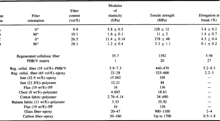
Table IV. Table Properties of the Different Manufactured Biocomposite Plates a Modulus
Fiber of
Plate Fiber content elasticity Tensile strength Elongation at
type orientation (vol%) (GPa) (MPa) break (%)
A 0 ~ 9.9 5.8 + 0.5 128 + 12 3.4 + 0.2
B 90 ~ 10.1 1.6 +__ 0.1 11 + 2 1.4 + 0.7
C 0 ~ 26.5 11.4 + 0.14 278 + 48 4.3 + 0.4
D 90 ~ 28.1 1.2 +__ 0.4 3.3 __. 1.1 0.1 + 0.2
Regenerated cellulosic fiber 35.7 1392 5.98
PHB/V matrix 1 20 27
Reg. cellul, fiber (35 vol%)-PHB/V 5.9-7.3 440-470 5.2-8.3
Reg. cellul, fiber (65 vol%)-epoxy 22-28 525-600 2.2-3
Jute (32.9 wt%)-epoxy 15.042 104 --
Jute (21.8%)-polyester 12.21 84 --
Flax (19 wt%)-PP 16 136 --
Choir (9 wt %)-polyester 4.045 18.61 --
Cotton fabric-polyester 2.76-4.14 34-690 --
Banana fabric (11 wt%)-polyester 3.33 35.92 --
Flax (19 wt%)-PP 16 136 --
Glass fiber-epoxy 20-47 900-1100 2-4
Carbon fiber-epoxy 20-160 Up to 1700 0.5-1.8
aAt least 10 samples were tested. The test speed was 10 mm/min, or 2 mm/min for elastic modulus measurements of samples C and D. Mechanical properties of the fiber and PHB/V matrix and comparison with other unidirectional fiber-reinforced composites [3, 24, 30-32].
164 B o u r b a n et al. 1 . 4 1 _ + + - ~ r 1.21 + + + ~ - + - 1 . - ~ " C o m p o s i t e with b l o w e r ~" ~ T / J ~ (4 layers, 500 filam./roving)
~
~L~ /J~
~'~0 6 t J-" ~ C o m p o s i t e without b l o w e r o ' ~ ] (1 layer, 1000 filam./roving) 0 4 t ~ T h e o r y 0 t 0 20 30 40 50 60Fiber Volume Content [vol%]
Fig. 3. Comparison of the measured fiber volume content (volumetrically) with the theo- retical fiber content, obtained by the rule of mixture applied to the elastic modulus of the composite.
Fig. 4. SEM image of the tensile fracture surface of the biodegradable composite (type A, 0~ fiber orientation) shows a homogeneous fiber distribution and a low fiber volume content.
Fiber Distribution, Wetting, and Interfacial Adhesion
Optical characterization of the tensile fracture sur- face by SEM showed that fiber distribution was signif- icantly improved, compared to previous work [3]. Each filament was wetted with matrix and their distributions showed only slight variation (Fig. 4).
SEM images (Fig. 5) indicate a poor fiber-matrix adhesion because of the clean and smooth topography of fiber prints in the matrix. This was essentially due to the contrary surface characteristics of the hydrophilic fi- ber and the hydrophobic matrix. A weak interfacial shear strength is advantageous for energy and impact absorp- tion but disadvantageous for load-beating applications. The matrix between two fibers formed waved lips, in- dicating a tough behavior of the PHB/V matrix.
The samples with - 2 7 vol% fiber were investi- gated by light microscopy. From the observation of the fracture surface, it could be seen that the number of fiber pullout increased with the fiber content.
CONCLUSIONS
In contrast to previous studies [3], problems of in- sufficient wettability of the fibers by the matrix and in- homogeneity of the fiber distribution could be solved with the proposed processing unit. The biodegradable composite showed that a fiber content of about 27 vol % (volumetric determination) can be reached by optimiz- ing the process parameters. The calculated porosity of the composite is comparable to conventional compos- ites. Further optimization of the adhesion between cel-
Fig. 5. SEM image of a fracture surface of the biodegradable composite (type B, 90 ~ fiber orientation) shows good wetting of the fibers by the matrix. The smooth prints of the fibers indicate poor adhesion of the matrix to the fibers, while the waved lips indicate a tough behavior of the matrix.
166 Bourban et al.
lulosic fiber and PHB/V matrix is necessary. There is a wide variety of coupling agents or fiber surface treat- ments mentioned in the literature [4, 15, 16, 26, 28, 29], but their applicability and efficiency on regenerated cellulosic fibers remain to be seen. Poor interfacial adhesion, however is needed in applications where en- ergy or impacts are to be adsorbed. Ongoing research is aimed at improving the adhesion between the fiber and the matrix, so that the biodegradable composite could benefit from an even wider application range,
The results demonstrate promising mechanical properties of the PHB/V-regenerated cellulosic fibers composite. As predicted by unidirectional fiber rein- forcement theory, cellulosic fibers significantly increase the stiffness and strength of the PHB/V matrix while maintaining the biodegradability of this material.
ACKNOWLEDGMENTS
This study was supported by European Community Project AIR2/CT93-1099, "Biodegradability of Bio- polymers: Prenormative Research, Biorecycling and Ecological Impact," and Swiss Federal Office for Ed- ucation and Research Grant No. 93.0279.
REFERENCES
1. J. M. Felix and P. Gatenholm (1991) J. Appl. Polym. Sci. 42, 609-620.
2. P. Gatenholm, J. Kubat, and A. Mathiasson (1992) J. Appl. Polym. Sci. 45, 1667-1677.
3. B. Koch, K. Ruflieux, J. Mayer, and E. Wintermantel (1994) Biodegradable Textile Reinforced Polymers: Processing of a New Degradable Composite, International Techtextil Symposium in Frankfurt/Main, Germany, 6 Internationales Techtextil Sympo- sium, '94, 3.2, 3.22
4. C. Klason, J. Kubat, and P. Gatenholm (1989) in H, Inagaki and G. O. Phillips (Eds.), Cellulosics Utilization, Research and Re- wards in Cellulosics: Proceedings of the Nisshinbo International Conference on Cellulosics Utilization in the Near Future in To- kyo, Japan, Elsevier Applied Science, London, pp. 89-96. 5. S. Akhtar, C. W. Pouton, and L. J. Notarianni (1992) Polymer
33, 117-126.
6. P. J. Hocking (1992) J.M.S. Rev. Macromol. Chem. Phys. C32, 35-54.
7. A. U. Daniels, M. K. O. Chang, and K. P. Andriano (1990) J. Appl. Biomater. 1, 57-78.
8. P. A. Holmes (1985) Phys. Technol. 16, 32-36.
9. G. R. Lightsey, P. H. Short, and K. K. Sinha (1977) Polym. Eng. Sci. 17, 305-310.
10. J. Felix (1993) Enhancing Interactions Between Cellulose Fibers and Synthetic Polymers, Ph.D. thesis, Department of Polymer Technology, Chalmers University, G6teborg.
11. A. K. Bledzki, S. Reihmane, J. Gassan (1996) J. ofAppl. Polym. Sci. 59, 1329-1336.
12. A. Nagaty, O. Y. Mansour, and A. B. Mustafa (1983) Polym. Sci. Technol. 17, 149-169.
13. P. Zadorecki and K. B. Abbas (1985) Polym. Composites 6, 162- 167.
14. V. I. Popa and I.-G. Breaban (1995) Cellulose Chem. Technol. 29, 575-587.
15. R. G. Raj, B. V. Kokta, D. Maldas, and C. Daneault (1989) J. Appl. Polym..Sci. 37, 1089-1103.
16. P. Gatenholm, J. Felix, C. Klason, and J. Kubat (1992) Con- temp. Topics Polym. Sci. 7, 75-82.
17. H. Brandl, J. Mayer, and E. Wintermantel (1995) Can. J. Mi- crobial. 41, 1-11.
18. J. Mergaert, C. Anderson, A. Wouters, J. Swings, and K. Kers- ters (1992) FEMS Microbiol. Lett. 52, 317-322.
19. Y. Doi (1990) Microbial Polyesters, VCH Verlag, New York. 20, Y. Doi, Y. Kanesawa, and M. Kunioka (1990) Macromolecules
23, 26-31.
21. Monsanto (1996) Technical Brochure: Biopol TM Resin, Nature's
Plastic, Properties and Processing, Monsanto GmbH, Immer- mannstrasse 3, D-40210 Diisseldorf, Germany.
22. G. J. M. de Koning (1993) Prospects of Bacterial Poly(R)-3- Hydroxyalkanoates, Ph.D. thesis, Academic Department of Bio- polymers, Technische Universiteit Eindhoven, Eindhoven. 23, W. Michaeli and M. Wegener (1990) Einfahrung in die Tech-
nologie der Faserverbundwerkstoffe, Carl Hanser Verlag, M0nchen.
24. E. Baer and A. Moet (1991) High Performance Polymers-- Structures, Properties, Composites and Fibers, 1, Hanser, Mu- nich, pp. 212-213.
25. A. R. Bunsell (1988) Fibre Reinforcement for Composite Mate- rials, in Composite Materials Series, Vol. 2, R. B. Pipes (Ed.), Elsevier, Amsterdam.
26. H. Dalviig, C. Klason, and H.-E. Str6mvall (1985) Int. J. Polym. Mater. 11, 9-38.
27. D. T. Quillin, M. Yin, J. A. Koutsky, and D. F. Caufield (1994) J. Appl. Polym. Sci. 52, 605-615.
28. R. Narayan (1989) in H. Inagaki and G. O. Phillips (Eds., Cel- lulosics Utilization, Research and Rewards in Cellulosics: Pro- ceedings of the Nisshinbo International Conference on Cellulos- ics Utilization in the Near Future in Tokyo, Japan, Elsevier Applied Science, London, pp. 110-118.
29. D. Maldas and B. V. Kokta (1993) Composites Interfaces 1, 87- 108.
30. L. A. Pilato and M. J. Michno (1994) Advanced Composite Ma- terials, Springer-Verlag, Berlin, pp. 97-127.
31. K. P. Mieck, A. Nechwatal, and C. Knobelsdorf (1993) The Po- tential Uses of Natural Fibres in Composite Materials, Vol. 3.1, International Techtextil Symposium in Frankfurt, Germany, p. 3.11.
32. M. R. A. Rowell, P. K. Rohatgi, K. G. Satyanarayana, and N. Chand (1991) Natural Composites, Fiber Modification and Nat- ural Fiber Composites, in International Encyclopedia of Com- posites, Vol. 4, S. M. Lee (Ed.), VCH, Weinheim, New York, pp. 1-16.