Publisher’s version / Version de l'éditeur:
Vous avez des questions? Nous pouvons vous aider. Pour communiquer directement avec un auteur, consultez la première page de la revue dans laquelle son article a été publié afin de trouver ses coordonnées. Si vous n’arrivez pas à les repérer, communiquez avec nous à [email protected].
Questions? Contact the NRC Publications Archive team at
[email protected]. If you wish to email the authors directly, please see the first page of the publication for their contact information.
https://publications-cnrc.canada.ca/fra/droits
L’accès à ce site Web et l’utilisation de son contenu sont assujettis aux conditions présentées dans le site LISEZ CES CONDITIONS ATTENTIVEMENT AVANT D’UTILISER CE SITE WEB.
Building Research Note, 1976-11
READ THESE TERMS AND CONDITIONS CAREFULLY BEFORE USING THIS WEBSITE. https://nrc-publications.canada.ca/eng/copyright
NRC Publications Archive Record / Notice des Archives des publications du CNRC :
https://nrc-publications.canada.ca/eng/view/object/?id=c039f4c1-81fe-4d0a-92f9-5e5279d9c93c https://publications-cnrc.canada.ca/fra/voir/objet/?id=c039f4c1-81fe-4d0a-92f9-5e5279d9c93c
NRC Publications Archive
Archives des publications du CNRC
This publication could be one of several versions: author’s original, accepted manuscript or the publisher’s version. / La version de cette publication peut être l’une des suivantes : la version prépublication de l’auteur, la version acceptée du manuscrit ou la version de l’éditeur.
For the publisher’s version, please access the DOI link below./ Pour consulter la version de l’éditeur, utilisez le lien DOI ci-dessous.
https://doi.org/10.4224/40000593
Access and use of this website and the material on it are subject to the Terms and Conditions set forth at
Net annual heat loss factor method for estimating heat requirements of buildings
ISSN 0701-5232
NET
ANNUAL
HEAT LOSS FAC'SORMETHOD
FORESTIMATING E A T
REQUIREMENTS OFBUILDINGS
G.P. Mitalas
Division of Building Research, National Research Council of Canada
NET ANNUAL HEAT LOSS FACTOR METHOD
FOR ESTIMATING HEAT REQUIREMENTS OF BUILDINGS
G.P. MitaXas
The development of energy budget standards for b u i l d i n g s makes it necessary f o r designers t o produce accurate estimates of t h e amount of energy required to heat a building. The most widely used
method of calculating annual h e a t i n g requirement is the ASHRAE degree-day procedure [Ref. 1, see p . 4 3 . 8 ) :
where
E = annual heating requirement
D = number of degree-days for heating season, calculated 'by summing the daily values o f the d i f f e r e n c e between
65°F and the mean of the maximum and minimum
temperatures for t h e days for which t h e mean is lower t h a n 65OF
HL = d e s i g n heat l o s s (including infiltration)
At = design temperature d i f f e r e n c e
CD = correction f a c t o r , which depends on the outdoor d e s i g n
tenrperatzrre
CF = part-load correction f a c t o r for fueled systems only; equals 1.0 fir electric resistance heating
v
= rated f u l l load e f f i c i e n c y , equals 1.0 for electric resistance heatingV = heating value of fuel, consistent with R and E; equals
Equation (1) ignores the fallowing building design features: orientation of windows and colour of exterior surfaces of t h e building envelope, variations of infiltration rate with wind and
stack effect. This Note presents a modification of the degree-day method to allow designers to take more accurate account o f :
-
solar r a d i a t i o n incident on a building surface,-
variation of solar energy gained through windows (with orientation and type o f window),-
variation of a i r i n f i l t r a t i o n rate with wind speed and difference between inside and outside a i r temperature,-
heat generared by inside a c t i v i t y such as lights, people, etc., and its effect an building energy needs.This m o d i f i e d degree-day method is called the "Net Annual Heat Loss Factor'' method of e s t i m a t i n g heat requirements of buildings. It is based on t h e fact t h a t the t o t a l annual building h e a t l o s s can be separated i n t o the following four components:
1 . window heat l o s s ,
2. opaque wall and ceiling heat l o s s ,
3 . air infiltration-ventilation heat l o s s , 4 . basement (below ground) heat loss. Expressed in equation form it is:
+
%all and c e i l i n g
+
'air infiltration
Each of these heat l o s s components can be calculated separately using Net Annual Heat Loss Factors (NAHLF). The following sections describe how these factors have been evaluated and how they can be
used to estimate net annual heating requirements for simple buildings.
EVALUATING NAHLF FOR HOUSES
The values of the NAHLF given in this Note were determined by using a computer program ( 2 ) to evaluate the annual heating
requirements o f a "standard" and a m o d i f i e d bungalow exposed to " t e s t " year weather cycles for several locations across Canada. The various factoxs were obtained by making the annual heating
r e q u i ~ e m e n t calculation f i r s t for the standard house and then for a similar, m o d i f i e d house (for example, increased area of wall or window facing a particular d i r e c t i o n ) . The NAHLF value was obtained
by taking t h e d i f f e r e n c e between the standard case and t h e modified
case and d i v i d i n g the difference by the numerical value o f modification ( f o r example, extra area for wall. o r window). The standard house is assumed to be well insulated and
relatively tight - representative of the type o f construction t h a t
will probably be needed t o meet f u t u r e energy standards. It is a bungalow with the following features :
- length, 11.3 m
-
width, 8.5 m- gross floor area, 90 m 2
-
opaque exterior wall area, 71 m 2-
glazed area, 21 rn 2- basement wall above grade level, 19 m 2
2
- opaque wall thermal resistance, 4 . 2 rn -K/W
2
-
ceiling thermal resistance, 6 . 2 m . K / W- exposed basement wall thermal resistance 1 .S
~*.K/w
- occupancy, family af four persons-
appliances (television, stove, lights,refrigerator, etc.) approx. average, 1.4
kW
-
air leakage characteristics - infiltration x a t e of125 rn3/h at 30 K temperature d i f f e r e n c e and 4 m/r,
wind speed. Note t h a t this low leakage c h a r a c t e r i s t i c is possible with a " t i g h t " house w i t h o u t a chimney.
NAHLF were calculated f o r a range of degree-day values by
u s i n g test year (3) weather c y c l e s f o ~ Vancouver, Lethbridge, Saskatoon, Winnipeg, Toronto, Montreal, Fredericton, Halifax, and
St. John's. They are p l o t t e d a g a i n s t the degree-day value so that factors f o r any o t h e r locations in Canada can be estimated simply
by t a k i n g the heating degree-day value for the location in question (43 and reading the values of t h e NAHLF from the graphs. It should
be noted t h a t the h e a t i n g degree-days given in Supplement No. 4 to the National Building Code of Canada (43 are for temperature in F deg. They can be converted to metric equivalents and a base of
1 8 " ~ by a procedure given by Boyd (5). Window Heat Lass
Meat is t r a n s f e r r e d t h r o u g h windows by two d i f f e r e n t mechanisms:
- solar radiation through the window,
- heat transfer by the combined mechanisms of convection, conduction and long-wave r a d i a t i o n .
Heat loss by air leakage through cracks around t h e windoy frame is
t a k e n into account along with t h e rest o f the a i r leakage. It should be noted t h a t n e t annual heat loss through a window depends on
window orientation because o f the solar radiation admitted through it.
The value of t h e conduction/convection/long-wave radiation component, on t h e other hand, is independent o f direction: it is t h e product of window "Ut' value (where U is over-all window
conductance) and inside-outside temperature difference. The annual n e t heat l o s s through u n i t area o f windows, called Window Heat Loss
Factors, has been p l o t t e d a g a i n s t number o f degree-days f o r each of
eight o r i e n t a t i o n s ( F i g u r e s 1 to 3). The values used are for s i n g l e , double and triple glazing, respectively. The window f a c t o r s
correlate q u i t e well with t h e number o f degree-days f o r the v a r i o u s
localities, although the localities have d i f f e r e n t latitudes and d i f f e r e n t t y p e s of climate, It is possible, t h e r e f o r e , to use these graphs lo obtain window f a c t o r s f o r any l o c a l i t y where t h e number of h e a t i n g degree-days is known.
The Window Heat Loss Factor for an orientatjon that does not correspond e x a c t l y to one of the eight t h a t are p l o t t e d can be
obtained by interpolation of the given values. Once the Window Heat
Loss Factors, HLFWind,,, for all orientations and a l l windows in question have been determined, t h e annual heat l o s s through a l l the windows i n a b u i l d i n g can be calculated by:
Q*indow = sum of a l l
''Awindow
*
HLFwindow " p r o d u c t s f o r a l l windows i n the buildingwhere
HLFwindow = window Heat Loss Factor obtained from Figures 1, 2 or 3
*window = glazed area of t h e window.
Onaaue Wall H e a t Loss
Heat is lost through opaque segments of a building envelope by
conduction and air leakage. In this section only conduction heat
l o s s will be considered. (Heat loss by air leakage through all parts of the building enclosure is the subject o f the next section.)
Heat t r a n s f e r by conduction through a wall is proportional to t h e average temperature d i f f e r e n c e between the two surfaces of the wall. Surface temperatures, i n t u r n , are f u n c t i o n s of t h e air temperatures adjacent to the surfaces and the long- and short-wave radiation incident on t h e surfaces. The heat flux through an
opaque building envelope segment is, therefore, related t o the following basic parameters:
- inside and outside air temperatures,
-
wall conductance, i . e . , U value of the wall,-
solar r a d i a t i o n incident on the outer surface,- exterior surface solar absorptivity, i.e., colour of t h e
surface,
-
emissivity and absorptivity, e, of the surfaces for long-wave radiation ( e = 0.95 is typical for all types o f building enveloge surface except m e t a l ) .To facilitate the selection o f Wall H e a t Loss Factors for a given s e t of parameters the factors a r e plotted against degree-day values (see Figures 4 to 7) and normalized with respect to wall over-all conductance; t h i s , in turn, is t h e reciprocal of over-all thermal resistance.
The factors for specific wall exterior surface colour are given for only l i g h t , medrum and dark shades because t h e factors are n o t
particularly sensittve to this parameter. Tn the ceiling-roof system the colour of t h e roof has very little effect if the ceiling is reasonably well i n s u l a t e d . The effect of roof colour on ceiling heat loss factor can t h e r e f o r e be neglected. It should also be noted t h a t c e i l i n g factors p l a t t e d i n Figure 7 are normalized using
the conductance value of the ceiling because ceiling conductance is
the p r i n c i p a l factor governing heat loss through ceiling-roof
systems when the c e i l i n g is well insulated, Factors f o r o r i e n t a t i o n
o t h e r than one af the cardinal directions can be obtained by
interpolating the platted values.
The annual h e a t loss through a l l the opaque segments of a
b u i l d i n g can be calculated by:
Qopaque = sum of all the products "HLFWd 1 A W a l ~ / R W a l ~ ~ O T
all opaque segments of the building envelope (41 where
HLFwal 1 = wall heat lass factor t h a t is derived from Figures 4 ,
5, 6 or 7 ,
Rwal 1 = resistance of the element in question which includes inside and outside surface resistances,
*wall = area of the element in question,
Sensible Heat Loss by Air Infiltration
One of t h e major components of t h e annual heating requirement for most buildings is the energy needed to heat infiltration and v e n t i l a t i o n a i r . The crucial data f a r calculating this energy are the appropriate average rases o f infiltration f o r a whole heating
season. Reliable infiltration values are scarce, but some have been given b y Tamura and Wilson 16). h c c this infiltration has been established it is very simple to calculate the annual heat
loss by infiltration:
where
H L F i n f i 1 t
.
= infiltration heat loss factor given in F i g u r e 8 TR = building average infiltration rate over heatingseason. Basement Heat Loss
The prediction of the annual h e a t loss from a basement depends on the thermal characteristics of t h e surrounding ground, w e a t h e r ,
and the thermal characteristics of the building. These calculatians
SAMPLE CALCULATION
Calculate annual heat loss of a house located in Pine Falls,
Manitoba. The p e r t i n e n t house construction data are given in
Table 1.
The heating degree-days given in Supplement No. 1 t o the
National Building Code (4) f o r Pine Falls, Manitoba, is 11,000
Fahrenheit degree-days. Thus, in metric units and based on IsOC,
the number is 6011 ( 5 ) .
Determination of Heat Loss Factors f o r House in $estion Meat loss factors for 6011 K 0 d value are:
Windows (Figures 2 and 3):
Orientation Triple Glazed Double Glazed
180° -145 kW-hJ(m .yr?- 2 -55 k~-h/(rn~.yr)
Walls (Figures 5 and 6) :
O r i e n t a t i o n Co 1 our
Medium Dark
130 kh-K 128 kh.X
Ceiling (Figure 7 ) : 9 4 . 5 kh K
2 3
Infiltration heat loss factor (Figure 83 = 49 kW-h /m
The factors for the s p e c i f i e d orientations are obtained b y
interpolation. Thus, the heat loss factor for a double-glazed window o r i e n t e d 15 degrees W cf S (i.e., wall azimuth angle o f 19S0] is:
The f a c t o r s f o r o t h e r specified window and wall orientations
obtained in a similar way a r e given in Table TI.
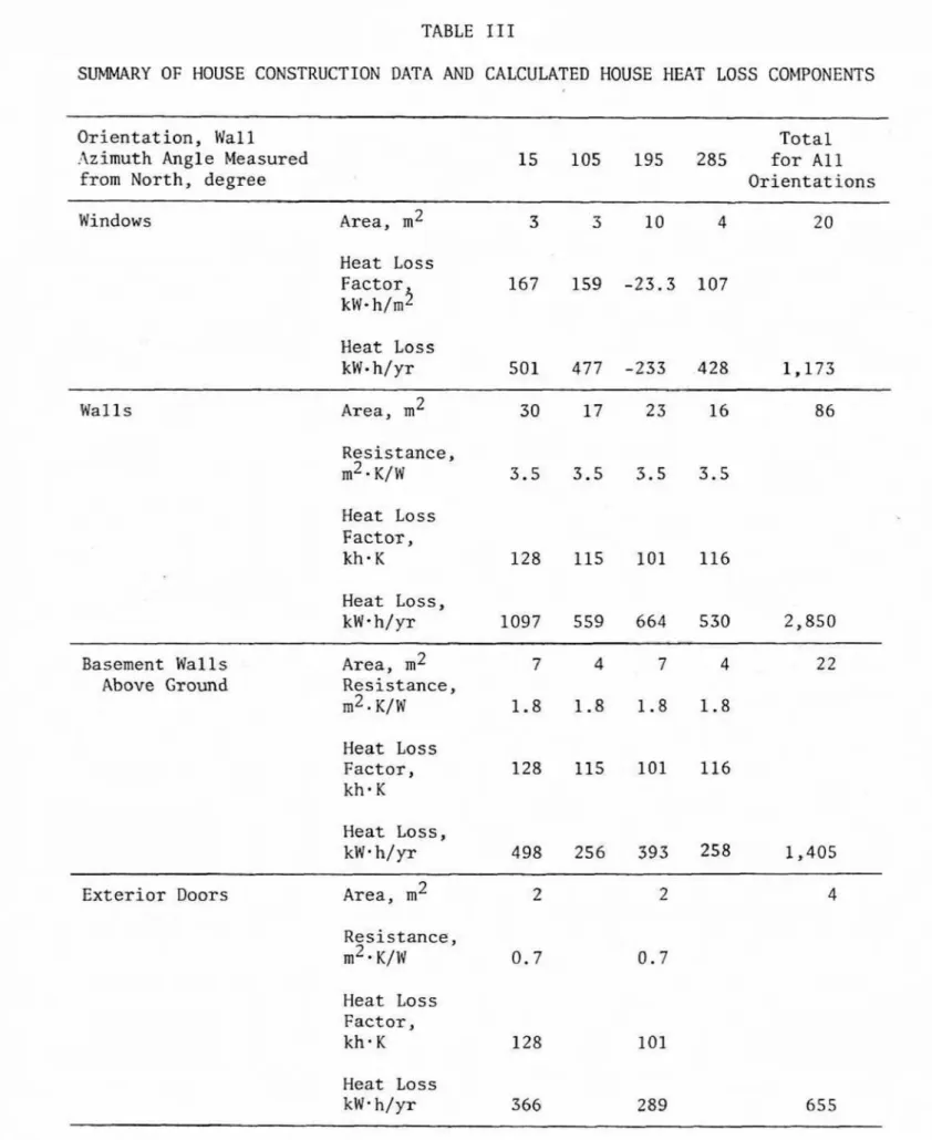
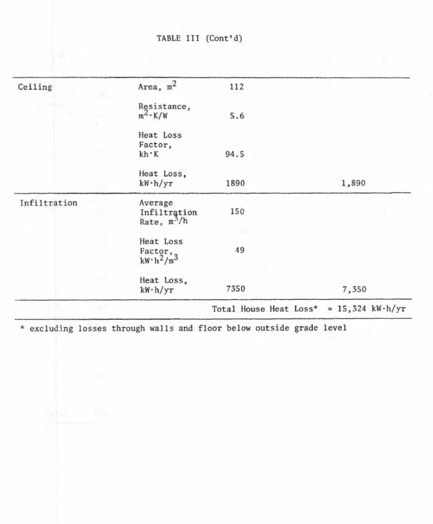
Calculation of Mouse Heat Loss
Window, wall, c e i l i n g and i n f i l t r a t i o n heat losses a r e calculated by Equations (33 (43 and (5), r e s p e c t i v e l y . The summary o f data and results are given in Table 111.
DISCUSSION
T o t a l house heat loss (except f o r basement below g r a d e )
calculated by the ASHRAE degree-day method [i.e., Equation (I]) is 1 4 , 8 8 0 kWmh/yr
w h e r e
3
H L / A t = 178 W/K (based on infiltration r a t e of 170 m J h
at design temperature of - 3 3 O C and 4 m / s wind speed*, i , e . , 0 . 3 3 air changes per hour]
CD = 0.57 (see Reference 1 : Table 11, p . 43.8)
C F , 0 and V = 1.0 (since f u e l fired equipment is not considered
in this sample problem).
3
* T h i s 170 m /h infiltration r a t e at d e s i g n c o n d i t i o n s of - 3 3 " ~ and 4 m / s wind speed is consistent with the average infiltration r a t e
This compares well with the t o t a l heat l o s s calculated by t h e Heat 1,oss Factor method. The agreement of house h e a t loss components
calculated by the t w o methods, however, is not so good as the comparison of the total losses (Table IV] where t h e highest
d i f f e r e n c e is in window and infiltration components, Thus, the good agreement of the total house heat loss values calculated by the two methods is due to compensating error in window and
i n f i l t r a t i o n h e a t loss components calculated by t h e ASHRAE degree-day method,
REFERENCES
1. A S H W Handbook; 1976 Systems Volume. American S o c i e t y of Heating, Refrigerating and Air-Conditioning Engineers.
2. Larsen, B.T. D i g i t a l Simulation of Energy Consamption in Residential Buildings. Presented at I n t e r n a t i o n a l C I B
Symposium on Energy Conservation in t h e Built Environment. Building Research Station, Garston, 6-8 A p r i l 1976.
3. Boyd, D. Procedure for Selecting a T e s t Year of Weather Data.
Private communicati~n.
4. Climatic Information f o ~ Building Design
in Canada,
1975. Supplement No. 1 to the National Building Code of Canada. 5. Boyd, D. Converting Heating Degree-Days from Below 6 5 O ~ toBelow 18'~. National Research Council of Canada, Division o f
Building Research, Building Research Note 98, 1975. 6 Tamura, G.T. and A.G. Wilson. A i r Leakage and Pressure
Measurements on Two Occupied Houses. ASHRAE Journal, V01. 5 , No. 12, Dec. 1963.
7 . Shirtliffe, C.J. and W.C. Brown. Basement Heat Loss.
TABLE
T
EXAMPLE PROBLEM: HOUSE CONSTRUCTTON DATA
rom North, degree
Opaque Exterior Walls
* M = ?qledium
TABLE 11
HEAT LOSS FACTORS FOR THE HOUSE OF EXAMPLE PROBLEM
Angle Measured
,
Wall Meat Loss Factor, kh- K Ceiling, kh- K 2 3 Infiltration,kW-h
$m Medium Colour Dark Colour 94.5 49 128 115 101 116TABLE IT1
SUMMARY OF HOUSE CONSTRUCTION DATA AND CALCULATED HOUSE HEAT LOSS COFIPONENTS
Orientation, Wall T o t a l
:lz imuth Angle Measured 15 105 195 285 f o r A 1 1
from North, degree Orientations
Windows - - - -Area, m 2 3 3 10 4 20 Heat Loss Factor k ~ . h/mZ Heat Loss k W - h J ~ x 501 477 -233 428 1 , 1 7 3 - - Walls -- Area, m 2 Resistance, m2
-
K/W Heat Loss Factor, kh.K Heat Loss, kW0h/yr 1097 559 664 530 2 , 8 5 0Basement Walls Area, m2 7 4 7 4 2 2
Above Ground Resistance,
m2 K/W 1 . 8 1.8 1 . 8 1.8 Heat Less F a c t o r , 128 115 101 116 kh* K Heat Loss, kW* h / y r 498 2 5 6 393 258 1,405 - - - E x t e r i o r Doors Area, m 2 Resistance, r n 2 v ~ / ~ 0.7 0.7 Heat Loss Fact or, kh- K 128 101 Heat Loss k W m h/yr 366 289
TABLE IIT (Cent' d) Ceiling Area, m 2 112 Resistance, m2 K/W Heat Loss Factor, kh'K 9 4 . 5 Heat Loss, kW . h / y r lg90 I n f f l t r a t i m Average Inf iltrqtion 150 Rate, m.'/h Heat Loss F a c t o r , 4 9 k~
-
h2/m3 Heat Loss, kW- hJyr 7350T o t a l House Heat Loss" = 15,324 kW-h/yr
TABLE
IV
HOUSE HEAT LOSS COMPONENTS CALCULATED BY
HEAT
LOSS FACTOR AND DEGREE-DAY METHODSHeat Loss Degree-Day
House Heat Factor Method Method Difference
Loss Component MW- h / p MW-h/yr MIV* h/ yr
Windows 1.17 E x t e r i o r Walls 2.85 Basement Walls Above Ground 1 . 4 1 Exterior Doors 0.65 0.48 - 0 . 1 7 Ceiling 1.89 1.67 - 0 . 2 2 Infiltration 7.35 4.73 -2.62 Total 15.32 1 4 -88 -0.44