HAL Id: inria-00099928
https://hal.inria.fr/inria-00099928
Submitted on 26 Sep 2006
HAL is a multi-disciplinary open access
archive for the deposit and dissemination of sci-entific research documents, whether they are pub-lished or not. The documents may come from teaching and research institutions in France or abroad, or from public or private research centers.
L’archive ouverte pluridisciplinaire HAL, est destinée au dépôt et à la diffusion de documents scientifiques de niveau recherche, publiés ou non, émanant des établissements d’enseignement et de recherche français ou étrangers, des laboratoires publics ou privés.
Instrumentation of the Jxta peer-to-peer framework
Rizi Mohanty
To cite this version:
Rizi Mohanty. Instrumentation of the Jxta peer-to-peer framework. [Internship report] A04-R-471 || mohanty04a, 2004, 45 p. �inria-00099928�
Instrumentation of the Jxta peer-to-peer framework
Summer Training Report (May’03 - July’03) Submitted in partial fulfillment of the requirements
for the degree of Bachelor of Technology
by
Rizi Mohanty Roll No: 01CS1036
under the guidance of Professor Olivier Festor
Department of Computer Science and Engineering Indian Institute of Technology
Kharagpur November 30, 2004
Abstract
Nowadays, Peer-to-Peer (P2P) networks and services are increasingly present in the networking world. Thus for this reason, management of such networks becomes important. In this summer training report, we will discuss our model for the management of JXTA which is a generic platform for the development of P2P applications. Our model is based on the generic management information model [4] already developed and adds new classes in order to instantiate the JXTA model absolutely. Then following the theoretical modeling is the part concerning the implementation of the model. This is to be achieved by deploying agents on each peer and then finally collecting the information data from each agent which would be done by a manager.
Acknowledgement
November 30, 2004
I would like to thank my guide, Prof. Olivier Festor for the consistent directions he has fed into my work. I am also thankful to Guillaume Doyen for all the help that he gave me. His constant motivation and encouragement proved to be extremely useful.
Rizi Mohanty 01CS1036
Contents
1 Introduction 7 2 Review of Literature 9 2.1 CIM . . . 9 2.2 The P2P Extension . . . 9 2.3 Instantiation on Chord . . . 10 2.4 Summary . . . 11 3 Project JXTA 13 3.1 JXTA . . . 13 3.2 JXTA Elements . . . 13 3.2.1 JXTA Peer . . . 13 3.2.2 JXTA PeerGroups . . . 14 3.2.3 Network Transport . . . 14 3.2.4 Services . . . 15 3.2.5 Advertisements . . . 16 3.2.6 JXTA Identifiers . . . 16 3.3 JXTA Protocols . . . 163.3.1 Core Specification Protocols . . . 16
3.3.2 Standard Service Protocols . . . 17
3.4 JXTA Monitor . . . 17
3.4.1 Overall Architecture . . . 18
3.4.2 Endpoint Service Metering . . . 19
3.4.3 Rendezvous Service Metering . . . 19
3.4.4 Resolver Service Metering . . . 20
3.4.5 Transport Metering . . . 20
4 JXTA modeling 23 4.1 JXTA peer, JXTA PeerGroup and virtual topology model . . . 23
4.2 JXTA communication model . . . 24
4.3 JXTA services model . . . 25
4.3.1 JXTA transport service model . . . 26
4.3.2 JXTA endpoint service model . . . 27
4.3.3 JXTA resolver service . . . 29
4.3.4 JXTA Rendezvous Service . . . 30 3
5 Implementation of the JXTA management information model 35
5.1 Deployment of an Agent . . . 35
5.1.1 JMX - Java Management Extensions . . . 35
5.1.2 Agent Implementation . . . 36
5.2 Prototype implementation . . . 39
5.3 Summary . . . 41
List of Figures
2.1 An overview of the CIM extension for P2P networks and services . . . 10
3.1 The Overall Architecture of the Monitor Project . . . 18
3.2 Endpoint Service Monitor Architecture . . . 19
3.3 Rendezvous Service Monitor Architecture . . . 19
3.4 Resolver Service Monitor Architecture . . . 20
3.5 Transport Service Monitor Architecture . . . 21
4.1 The peer and PeerGroup model . . . 24
4.2 The communication model . . . 25
4.3 The service handler model . . . 26
4.4 The transport service model . . . 27
4.5 The detailed transport service classes . . . 28
4.6 The endpoint service model . . . 29
4.7 The Detailed Endpoint Service Classes . . . 30
4.8 The resolver service model . . . 30
4.9 The detailed resolver service classes . . . 31
4.10 The rendezvous service model . . . 32
4.11 The detailed rendezvous service classes . . . 32
4.12 The dependency relationships . . . 33
4.13 The composition-aggregation relationships . . . 34
5.1 RMI scheme for manager and client . . . 40
Chapter 1
Introduction
The term Peer-to-Peer refers to a class of systems and applications that employ distributed resources to perform a critical function in a decentralized manner [4]. In other words P2P networking is built on a distributed model where peers are software entities which play the role of both client and server. The resources encompass computing power, data (storage and content), network bandwidth, and pres-ence (computers, humans and other resources). The critical function can be distributed computing, data/content sharing, communication and collaboration, or platform services. Typical P2P systems reside on the edge of the Internet or in ad-hoc networks. Today, the most famous application domain for P2P is file sharing with applications like Napster, Kaaza among others. However, we also have applications covering many additional domains of the P2P model like distributed computing, instant messaging etc.
The P2P model enables valuable service usage by aggregating and orchestrating individual shared resources [4]. The use of existing infrastructures that belong to different owners reduces the costs of maintenance and ownership. The decentralized topology increases fault tolerance by suppressing any central point of failure, and improves both load balancing and scalability. Also, the distributed nature of algorithms and some embedded mechanisms allow participating peers to keep a great level of anonymity.
Due to the growth of the web in terms of the number of devices and content, P2P is becoming increasingly popular. The existing applications are already dividing the whole P2P domain into various sub-domains like file sharing, instant messaging and so on. Even though all these applications perform different tasks, they all share many of the same properties, such as discovery of peers, resources, and content transfer. Currently, application development is redundant, with developers solving the same problems and duplicating similar infrastructure implementations. Most applications are specific to a single platform and are unable to communicate and share content with other applications. In order to
overcome these problems JXTA1
provides a generic platform with the basic functionalities necessary for a P2P network. JXTA is a set of open, generalized P2P protocols that allow any connected device on the network to communicate and collaborate as peers. JXTA seeks to overcome the potential shortcomings in many of the existing P2P systems:
Interoperability: the JXTA technology is designed to enable peers providing various P2P services
to locate each other and communicate with each other.
Platform Independence: the JXTA technology is designed to be independent of programming
1
www.jxta.org
languages, transport protocols, and deployment platforms.
Ubiquity: the JXTA technology is designed to be accessible by any device with a digital heartbeat.
While some P2P applications use built-in incentives as a minimal self management feature, ad-vanced management services are required for enterprise oriented P2P environments. The generic P2P
management information model [4] already existing is basically an extension of CIM2
[1, 6] classes and its upon this generic model that a information model dedicated for a P2P application can be developed. CIM has been used for the design of the model as it uses the object oriented model and presents a large set of classes covering several domains of computing that can be easily reused and extended.
JXTA, in order to be used more widely and also in enterprise domains, needs to provide perfor-mance service level agreements and some way to manage the P2P domain. Without any management of the JXTA P2P network, there is no way to evaluation in a fine grained way the performance of the peers and the network. In this report we present the information model dedicated to JXTA. This model is a sepcialization of the generic management information model [4]. With the theoretical model in place the next step that is described is the model implementation and integration along with the
JXTA platform. The implementation was done using JMX3
agents. These agents are to be used by the manager to obtain the values of management data from the client peers.
This report contains the description of the information model developed and also implementation of the agents on each peer. Finally the report discusses a very small managing application that can be used to manage just a single peer being run on the JXTA platform with the manager also being a JXTA peer. This small application defines the prototype which when extended would enable all the peers in a domain to be managed. So the information model and management architecture part of the management model are completed and discussed here. The prototype gives an idea about the protocol being used.
2
Common Information Model
3
Chapter 2
Review of Literature
The management model developed for JXTA is based on the generic management information model defined in [4]. This in turn is derived from the CIM classes. In this chapter, the CIM classes of this model and its extension are discussed with a small section on the Chord instantiation.
2.1
CIM
The DMTF Common Information Model [1, 6] is an approach to the management of systems and networks that applies the basic structuring and conceptualization techniques of the object-oriented paradigm. The approach uses a uniform modeling formalism that, together with the basic directory of object-oriented constructs, supports the cooperative development of an object-oriented schema across multiple organizations. A management schema is provided to establish a common conceptual framework at the level of a fundamental typology both with respect to classification and association, and with respect to a basic set of classes intended to establish a common framework for a description of the managed environment. The management schema is divided into these conceptual layers: Core Model: Its an information model [7] that captures notions that are applicable to all areas of
management.
Common Model: Its an information model [7] that captures notions that are common to particular management areas, but independent of a particular technology or implementation. The common areas are systems, applications, databases, networks and devices. The information model is specific enough to provide a basis for the development of management applications. This model provides a set of base classes for extension into the area of technology-specific schemes. The core and common models together are expressed as the CIM schema.
Extension Schemes: represent technology-specific extensions of the Common model. These schemes are specific to environments, such as operating systems.
2.2
The P2P Extension
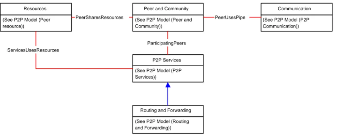
This section presents the CIM extension for P2P networks and services [4] and an overview of the design is represented in Figure 2.1. The CIM extension for the P2P networks and services aims at providing a general management information model, that is topology-oriented, for such a type of application. This way, it allows any P2P application to subclass it in order to provide dedicated
(See P2P Model (P2P Services))
P2P Services (See P2P Model (Peer and Community))
Peer and Community (See P2P Model (Peer
resource)) Resources
(See P2P Model (Routing and Forwarding))
Routing and Forwarding ParticipatingPeers ServicesUsesResources
PeerSharesResources (See P2P Model (P2P Communication))
Communication PeerUsesPipe
Figure 2.1: An overview of the CIM extension for P2P networks and services
classes that will represent the specific application features best. Instances of these classes will provide
a distributed MIB1
that a management application will use to administrate the application. The Model is composed of five main parts that are:
The peer and community model: models the notion of peers, community, virtual topology and
links this abstraction to the current Core classes.
The communication model provides information about the way peers communicate in terms of protocols and communication medias.
The resource model: informs about the resources a peer shares with another in order to contribute
to the smooth running of a service.
The service model: represents the services that can be provided and consumed in the context of
P2P networking.
The routing model: models the routing and forwarding services and the routing tables hosted by
peers.
2.3
Instantiation on Chord
The Chord framework is a P2P infrastructure for resource discovery. Its core principles confer good and stable properties to it, in terms of average path length, load balance, information consistency and resources distribution. Nonetheless, there is a need to monitor the performance of Chord systems on a real network. This section gives a very brief idea about the P2P information model [5], dedicated for the Chord framework.
Chord lies on a ring topology, a chord knows its predecessor and its successor. A consistent hash method generates a key for each node from its IP address. Then, each node is located in a ring in order to arrange keys in an increasing order. Each chord node is responsible for a particular range of keys. The metrics defined in the context to evaluate the performance of the chord network are incorporated into the model. The metrics are values like the total number of nodes, number of keys
1
in the ring and many more like that.
The management model for chord is performance-oriented and lies on the generic model for P2P networks and services discussed in the previous section. The models are divided into the following categories:
• The Chord Peer and Community Model • The Chord Resources Model
• The Chord Service Model
• The Chord Routing Table Model
Each of these model consists of classes that are dedicated for Chord but in turn are subclasses of the generic framework. The metrics are added in the proper classes so that the instantiation of these classes would correctly represent the Chord topology. Thus these models all taken together enable the evaluation of the global health state of a Chord community and to act consequently.
The goal of this instantiation on Chord are as follows:
• This instantiation proves that the model is valid by applying it on a real infrastructure.
• It provides an instrumentation model for Chord. There exist theoretical models, simulations but no real models that allow the performance evaluation of Chord in a real deployment.
2.4
Summary
In this chapter, we discussed the background that would be necessary in order to proceed further with the actual work discussed in this report. The section on CIM presents the core and common model in brief. The next section gives an overview of the generic management information model on which the Chord instantiation is done. Finally the instantiation on Chord proves that the model is not just correct on pen and paper but serves its purpose in a real infrastructure.
Chapter 3
Project JXTA
Even though most of the P2P solutions overlap in some shape or form, the current P2P applications tend to use protocols that are proprietary and incompatible in nature, reducing the advantage offered by gathering devices into P2P networks [2]. Each network forms a closed community, completely independent of the other networks and incapable of leveraging their services. To evolve P2P into a mature solution platform, developers need to create applications on a solid, well-defined base. JXTA provides the solution in form of a platform to develop P2P applications. JXTA is simply a set of protocol specifications, which is what makes it powerful. JXTA spares the developers of properly designing protocols to handle the core functions of P2P communication.
JXTA as a platform needs monitoring in order to find out about the performance of the various services under different network conditions. The theoretical model of JXTA does not provide any performance guarantees since it is only a platform on top of which the P2P applications are to be developed. Due to this reason it becomes even more important to monitor the services and the implementation of the JXTA protocols.
3.1
JXTA
JXTA protocols establish a virtual network overlay on top of the Internet and non-IP networks, allow-ing peers to directly interact and self-organize independent of their network connectivity [10]. These protocols define the minimum required network semantic for peers to form and join a virtual network. JXTA acts as a generic network substrate usable to build a wide variety of P2P networks. JXTA is also designed to be independent of programming languages, system platforms, service definitions and network protocols.
3.2
JXTA Elements
All P2P networks build upon fundamental elements and so does JXTA. The various core elements of JXTA are discussed in brief in this section.
3.2.1 JXTA Peer
A JXTA peer is a node on a P2P network that forms the fundamental processing unit of any P2P solution. JXTA defines the existence of three possible types of peers in any P2P network:
• Simple Peers
• Rendezvous Peers • Router Peers
Also each peer on the network can act as one or more types of peer, with each type defining a different set of responsibilities for the peer to the P2P network as a whole.
Simple Peers
A simple peer or edge peer is designed to serve a single end user, allowing the user to provide services from his device and consuming services provided by other peers on the network. Because of their limited network accessibility, simple peers have the least amount of responsibility in any P2P network and are not responsible for handling communication on behalf of other peers.
Rendezvous Peers
In JXTA, a rendezvous peer provides other peers with a network location in order to discover other peers and peer resources. A rendezvous peer can improve its performance by caching information and also by forwarding the discovery requests to other rendezvous peers. In JXTA 2.0 implementation,
rendezvous peers form a super peer network. Thus it introduces the concept of a RPV1
to propagate
resolver queries and SRDI2
to index advertisements on the RPV for efficient advertisement query lookups. Thus the rendezvous super peers organize themselves into a loosely-coupled network. The
above idea is based on the concept of DHT3
. Router Peers
A router peer provides a mechanism for peers to communicate with other peers separated from the
network by firewall or NAT4
equipment. A router peer provides a go-between that peers outside the firewall use to communicate with a peer behind the firewall and vice-versa. Routing a message through multiple router peers might be necessary to allow two peers to communicate by using the router peers to translate between two different and incompatible network transports.
3.2.2 JXTA PeerGroups
In JXTA since all the peers use the same protocols, the concept of peergroup becomes necessary to subdivide the network space. Hence in JXTA a peergroup is defined as a set of peers, formed in order to serve a common interest or goal dictated by the peers involved. Peergroups can provide services to their member peers that aren’t accessible by other peers in the P2P network. Each peergroup is uniquely identified by a unique peergroup ID. A peer can belong to multiple peergroups at the same time but at boot time, every peer joins the NetPeerGroup. The NetPeergroup acts as a root peergroup every peer initially belongs.
3.2.3 Network Transport
In order to exchange data, peers must employ some kind of mechanism to handle the transmission of data over the network. This layer, called the network transport, is responsible for all aspects of data
1
Rendezvous Peer View
2
Shared Resource Distributed Index
3
Distributed Hash Table
4
transmission. The concept of network transport can be divided into three parts that are discussed in this section.
EndPoints
Endpoints are the initial source or final destination of any piece of data being transmitted over the network. An endpoint corresponds to the network interface used to send and receive data. This helps the peer to send and receive data independent of the type of network transport being employed. A peer endpoint is associated with each peer encapsulating all available physical network addresses for the peer.
Pipes
Pipes are virtual communication channels used to send and receive messages between services and applications. Pipes provide a virtual abstraction over the peer endpoints to provide the illusion of virtual in and out mailboxes that are not physically bound to a specific peer location. Pipes can connect to one or more peer endpoints. JXTA core pipes provide communication in only one direction. The pipe ends are referred as the input pipe for receiving data and the output pipe for sending data. Pipes are uniquely identified in pipe advertisements by a pipe ID. JXTA core pipes offer two modes of communication:
A point-to-point pipe connects exactly two pipe ends with a unidirectional and asynchronous chan-nel, an input pipe end that receives messages sent from the output end of the pipe. It can be secure if desired.
A propagate pipe connects one output pipe to multiple input pipes. Message via this pipe is sent to all listening input pipe ends in the current peergroup context.
Messages
Messages are the basic unit of data exchange between the peers and peers interact by sending and receiving messages. A message is an ordered sequence of named and typed contents called elements. In short we can define them to be containers for data to be transmitted over a pipe from one endpoint to another.
3.2.4 Services
Services provide functionality that peers can engage to perform useful work on a remote peer [11].
This work might include transferring a file, providing status information, performing a calculation or anything else. JXTA services can be broadly divided into two categories:
Peer Services: These services are the functionality offered by a particular peer on the network to
other peers. This service is available only when the peer is connected to the network.
Peergroup Services: These services are the functionality offered by a peergroup to member peers
of the group. The functionality could be provided by several members of the peergroup and hence as long as one of these members is connected, the service is available.
Most of the functionality required to create and maintain a P2P network, such as the underlying protocols to discover peers, could be considered as services. These core services provide the basic P2P foundation used to build other, more complex services.
3.2.5 Advertisements
All network resources in the JXTA network, such as peers, peergroups, pipes and services are rep-resented by advertisements. Advertisements are language neutral metadata structures resource de-scriptors represented as XML documents. JXTA standardizes advertisements for the following core JXTA resource: peer, peergroup, pipe, service, metering, route, content, rendezvous, peer endpoint, transport.
3.2.6 JXTA Identifiers
Most items in JXTA P2P network need some piece of information that uniquely identifies them on the network. This is turn leads to the JXTA addressing model and JXTA IDs. JXTA provides IDs for the following: peers, peergroups, pipes and contents. IDs make the resources independent of their physical locations.
3.3
JXTA Protocols
Every data exchange relies on a protocol to dictate what data is sent and in what order it is sent. Its a way of structuring the exchange information between two or more parties using rules that have previously been agreed upon. The JXTA protocols are six in number divided into two categories:
• Core Specification Protocols • Standard Service Protocols
3.3.1 Core Specification Protocols
The functionality of all implementations is defined by the JXTA Core Specification protocols. These are essential for all implementations of JXTA and cannot be done without. The Core Specification consists of two protocols.
Endpoint Routing Protocol (ERP)
ERP is the protocol by which a peer can discover a route 5
used to send a message to another peer. If a peer A wants to send a message to peer C, and there is no direct route between A and C, then peer A needs to find the intermediary peer(s) to route the message to C. So ERP is used to manage and determine the routing information.
Peer Resolver Protocol (PRP)
PRP is the protocol by which a peer can send a generic resolver query to one or more peers, and receive responses for the query. The PRP protocol permits the dissemination of generic queries to one or more handlers within the group and to match them with responses. Each query is addressed to a specific handler name.
5
3.3.2 Standard Service Protocols
The JXTA Core Specification defines the required components and behaviors for all JXTA implemen-tations. In order to create a complete JXTA implementation there are some additional components which should be provided. The JXTA Standard services are optional JXTA protocols and behav-iors. Implementing these services will provide greater interoperability with other implementations and broader functionality.The Standard Services protocols specification defines four protocols: Rendezvous Protocol (RVP)
RVP is the protocol by which peers can subscribe or be a subscriber to a propagation service. Within a peergroup, peers can be rendezvous peers, or peers that are listening to rendezvous peers. RVP allows messages to be sent to all of the listeners of the service. RVP is used by the Peer Resolver Protocol in order to propagate messages.
Peer Discovery Protocol (PDP)
PDP is the protocol by which a peer publishes its own advertisements, and discovers advertisements6
from other peers. PDP uses the Peer Resolver Protocol for sending and propagating discovery requests. Peer Information Protocol (PIP)
PIP is the protocol by which a peer may obtain status information about other peers, such as state, uptime, traffic load etc. PIP uses the Peer Resolver Protocol for sending and propagating peer information requests.
Pipe Binding Protocol (PBP)
PBP is the protocol by which a peer can establish a virtual communication channel or pipe between
one or more peers. The PBP is used by a peer to bind the two or more pipe ends7
of the connection to a physical peer endpoint. PBP also uses Peer Resolver Protocol for sending and propagating pipe binding requests.
3.4
JXTA Monitor
JXTA is an extensible framework of services available to a peer within a peergroup. Many of these services will cause loads on the underlying systems. For standard JXTA services such a endpoint, transport, rendezvous etc., the service load will correlate to overall memory utilization, overall thread utilization and network connections and bandwidth. Also there is a need to determine the effects and efficiencies of new service implementations for inclusion in peergroups. Thus the JXTA Metering and Monitoring Project [3] creates and provides metrics for core JXTA services. The project also address the following and many more issues:
• Increased productivity of JXTA Core development
• Provide metrics to tune and configure the JXTA networks • Provide data to measure and prove scalability of JXTA
6
peer, peergroup, pipe and content advertisements
7
The goal of the JXTA MMP8
is to provide a simple, dynamic and extensible framework for gath-ering and reporting metrics about JXTA services running within peergroups. The types of metrics maintained for a service will be defined per service implementation. The PIP is a conduit for obtaining these metrics from remote peers. MMP includes the JXTA Monitor, which is a GUI for collecting and rendering metered data. This provides a framework for displaying metrics in a tabular or graphical manner.
3.4.1 Overall Architecture
The MMP consists of an architecture that allows aggregation and dissemination of metrics from JXTA services or any other type of monitor [3]. For services that provide metrics, publication of the metric format will become part of the service definitions. Metrics for all the standard services are already defined and will be discussed in the following part. A monitor is available for every local peer in a peergroup that provides an API for obtaining either runtime metric totals for one or more JXTA service or for registering listeners that will receive periodic updates of metric data. The peer information service needs to be extended to provide mechanisms to request metrics from remote peers.
PeerInfoService
MonitorManager
ServiceMonitor Meterable JXTA Service
Monitor report
Request for (Monitor filter)
ServiceMonitor ServiceMonitor
Meterable JXTA Service Meterable JXTA Service
API view
SPI view
Figure 3.1: The Overall Architecture of the Monitor Project
The important terms with respect to the MMP are: Monitor Point
A monitor point is a source of data that is established on a local or remote peer for providing metered data of a specified type at specified intervals.
Service Monitor
In order to collect a specific type of metric data from a service on a peer, there must be a dedicated service monitor for running. This information about which service monitors are running is obtained via the PIP.
Service Filter
The type of metrics received from a specific service monitor on a peer is determined by a service-specific service filter corresponding to that type of service monitor.
8
Monitor Filter
Since metric clients9
may not be interested in all metrics for a peergroup, any request for metrics must be accompanied by a monitor filter that specifies which service metrics are desired. Monitor filter is a collection of service specific service filters.
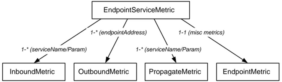
3.4.2 Endpoint Service Metering
The endpoint service provides the following functionality:
• Receives messages and redirects them to registered listeners based upon a service name and parameter pair.
• Provides messengers based upon endpoint address for sending messages.
• Provides a mechanism to propagate messages based upon a service name and parameter pair. The architecture for the endpoint service monitor is shown in Figure 3.2.
EndpointServiceMetric
InboundMetric OutboundMetric PropagateMetric EndpointMetric
1-* (endpointAddress)
1-* (serviceName/Param) 1-1 (misc metrics)
1-* (serviceName/Param)
Figure 3.2: Endpoint Service Monitor Architecture
3.4.3 Rendezvous Service Metering
The rendezvous service maintains the propagation-web for the peergroup. While every peer provides all the functionality of the rendezvous service, they interact with other peers in one of two roles -client or rendezvous. Clients are connected to zero or one rendezvous, while a rendezvous will have zero or more clients connected to them.
The architecture for the rendezvous service monitor is shown in Figure 3.3. RendezvousServiceMetric
RendezvousConnectionMetric ClientConnectionMetric RendezvousMetric
1-* (ClientConnection)
1-1 (misc metrics) 1-* (RendezvousConnection)
Figure 3.3: Rendezvous Service Monitor Architecture
9
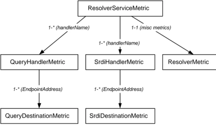
3.4.4 Resolver Service Metering
The resolver service provides a query and response framework. Within the resolver service there are registered handlers for sending and receiving both queries and responses. The resolver service utilizes the rendezvous service for the propagation of queries. In order to optimize the search of resources, the concept of SRDI comes up and there are handlers for this also. Detailed metrics about specific interactions with unicast endpoints are also maintained.
The architecture for the resolver service monitor is shown in Figure 3.4. ResolverServiceMetric
QueryHandlerMetric SrdiHandlerMetric ResolverMetric
1-* (handlerName) 1-1 (misc metrics) 1-* (handlerName) QueryDestinationMetric SrdiDestinationMetric 1-* (EndpointAddress) 1-* (EndpointAddress)
Figure 3.4: Resolver Service Monitor Architecture
3.4.5 Transport Metering
Transport metering does not correspond to any specific standard JXTA service or module. It provides a framework for monitoring any type of transport layer that:
• Establishes and maintains transport-layer connections • Sends and receives messages
• Broadcasts messages
Transport information in JXTA is kept per binding, where a binding corresponds to a transport layer endpoint address. At any point of time, there can be at most one peer associated with the peergroup that is managing the transport. The transport metric corresponds to a particular type of
transport10
and contains a list of binding metrics to actual peers.
Its possible due to the dynamic nature of JXTA that there can be more than one connection
between two peers at one point of time. One can be locally initiated 11
and the other can be
re-motely initiated 12
. The transport metrics are maintained separately for both the connections. The architecture for the transport service monitor is shown in Figure 3.5.
The service monitors for pipe service and discovery service have not yet been implemented in the JXTA MMP and hence their metrics are yet to be defined.
10 Like TCP, HTTP and so on 11 Initiator connection 12 Acceptor connection
TransportServiceMetric
TransportMetric
1-* (TCP-Unicast, Multicast, ServletHTTP, ...)
TransportBindingMetric
1-* (one per destination peer)
Chapter 4
JXTA modeling
Given the objective of managing the JXTA platform, we propose a management information model for JXTA that is based upon the generic model for P2P networks and services already described in section 2.2. But one of the points that needs to be stressed here is that the metrics used in the model designed are the ones that already exist in the JXTA MMP [3] and were discussed in the previous chapter. Since JXTA already has the metrics defined for each of the services, so instead of creating another set of similar metrics, I decided to use the same ones in the management framework. This provides following advantages:
• With the metrics are already incorporated inside the JXTA platform and instrumentation code done, implementation of the JXTA management information model would become easier. • In defining another set of metrics, we would need to change and update the whole JXTA
frame-work which is not our aim. Our goal is simply to manage the platform and provide performance guarantees.
The model also depicts a similar architecture to that of the JXTA MMP so as to fit in the existing metrics properly. The following sections present the JXTA model and the way the metrics have been applied to it.
4.1
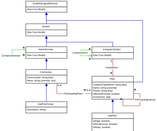
JXTA peer, JXTA PeerGroup and virtual topology model
The model is represented in Figure 4.1. In order to model a peer from a management point of view in JXTA, we have designed the JXTAPeer class that inherits from the Peer class of the P2P model as an extension of CIM classes. A peer in JXTA can be of one or more of the following types:
• Simple or Edge Peer • Rendezvous Peer • Relay Peer
The first attribute of the JXTAPeer class gives the time at which the peer started operation or came up and hence gives an estimate of the time for which it has been in the network. Then the second set of attributes give the basic idea about the type of peer it is. As described earlier, JXTA peer can act as one or more type even though most commonly the peers are of edge type. So when there is a transition from edge to rendezvous, it is indicated by the state of the attributes. These attributes are best placed in this class as they give the idea about the peer and help the class in representing the
(See Core Model)
EnabledLogicalElement
System
(See Core Model)
ComponentCS
*
*
CommunityId: string {key} Name: string {override, key}
Community
CreationClassName: string {key} Name: string {override} PeerId: string {key} IsBehindFirewall: boolean ArrivalTime: date Peer HostedPeer
*
1 ParticipatingPeers 1..n W 1..n(See Core Model) AdminDomain ContainedDomain
*
*
P2PTopologicalLink*
*
ComputerSystem (See Core Model)Description: string JxtaPeerGroup IsEdge: boolean IsRendezvous: boolean IsRelay: boolean JxtaPeer
Figure 4.1: The peer and PeerGroup model
JXTA peer properly. A JXTA peer also has attributes like name, ID which are inherited from the superclass and hence do not require to be defined in the subclass again. Another possibility was to model each type of peer differently such as EdgePeer, RendezvousPeer and RelayPeer but then the model would not correctly represent a peer, the reason being that a peer can transit between different types. The JXTAP2PTopologicalLink association class which is represented in Figure 4.1 gives the type of topological link between any two peers with the description of the link. This link establishes the virtual topology of a JXTA network representing all the types of connections between peers. The Description attribute in the class describes the type of link between the peers.
As for a peergroup in JXTA, the JXTAPeerGroup class is used to model it. It inherits from the
Communityclass of the P2P model. The only attribute in this class is the description of the peergroup
which is a part of the advertisement for a peergroup in JXTA. Also peers can belong to different peergroups which is already modeled in the P2P model.
4.2
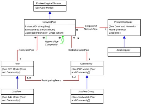
JXTA communication model
In JXTA, all the communications take place through endpoints. Pipes are abstractions over these endpoints. The proposed model is represented in Figure 4.2. The endpoints are modeled by the
JXTAEndpoint class. This class is inherited from the CIM class of ProtocolEndpoint. The attributes
of the class consist of all the metrics defined in JXTA for the state of the endpoint. So it was logical to put the endpoint state metrics in this class. These metrics are shown in Figure 4.7 under the same class name as JXTAEndpoint. The metrics give an idea about the overall number of messages
received by the particular endpoint and other similar details. The EndpointStartTime attribute tells the amount of time the endpoint has been running and when it started.
(See Core Model)
EnabledLogicalElement
InstanceID: string {key} Directionality: uint16 {enum} AggregationBehavior: uint16 {enum}
NetworkPipe
HostedNetworkPipe
ProtocolEndpoint (See Core and Networks Model (Protocol Endpoints)) EndpointOf NetworkPipe NetworkPipe Composition
(See P2P Model (Peer and Community))
Community (See P2P Model (Peer
and Community)) Peer ParticipatingPeers 1
*
2*
*
*
1..n 1..n PeerUsesPipe*
2 w(See Jxta Model (Peer and Community))
JxtaPeer
(See Jxta Model (Peer and Community))
JxtaPeerGroup
JxtaEndpoint
Figure 4.2: The communication model
The other class that is defined in the context of communication is the JXTAPipe class. This class is used to model JXTA pipes which already have been presented in the previous chapter. One important point that needs to be stressed here is the way we have modeled propagate pipes. It is done by the attribute AggregationBehavior which describes the way the NetworkPipeComposition relation acts. Propagate pipes are treated as a collection of unicast pipes with all having one common end to push data but different ends to receive data. Another problem in the model is its inability to represent the fact that in JXTA, pipes need not always be bound to two endpoints. Since pipe is a virtual entity, it is identified by an advertisement and binding a pipe to a endpoint is necessary to transmit data. But once the advertisement is created it needs not be bound to two endpoints immediately. This problem though cannot be solved since the CIM classes are defined in a way as to bind a pipe to two endpoints. So the changes in order to accommodate this need to be done in the generic information model. The other features are basically similar to that of the generic model and hence need not be elaborated.
4.3
JXTA services model
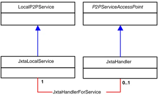
JXTA services are the ones for which the MMP defines the metrics. Hence the models for services become very important in the context of management. Services are implementations of the protocols by which the entire JXTA platform and network operate. Thus, monitoring of services becomes important in order to understand the amount of load handled by each peer and the network. As detailed earlier, we have used the same metrics for the services as defined in the metering project. Before going on to describe the model for each of the services we would like to discuss the overall service model for JXTA. The model for transport services gives a good idea about the whole picture and is represented in Figure 4.4. In case of JXTA we discuss all the services from a local view and
hence we inherit the JXTALocalService from the LocalP2PService of the P2P model. All the other features remain the same and hence need not be discussed here.
LocalP2PService JxtaLocalService P2PServiceAccessPoint JxtaHandlerForService 0..1 1 JxtaHandler
Figure 4.3: The service handler model
The class JXTAHandlers which is shown in Figure 4.3 is designed to help in modeling the handlers for certain services. Handlers in JXTA perform the job of listeners and do the processing accordingly. Say for example, the resolver service is used to send queries and responses also. When the discovery service for a particular peer runs it uses the resolver service in order to send the discovery query and also get the responses. So now there is a handler for discovery service registered with the resolver service. The messages directed for this discovery service are received by the resolver service and then processed by the handler for discovery. So this is how the handlers perform in JXTA. The JXTAHandler class is inherited from the ServiceAccessPoint class of the core model of CIM as a handler functions to
a SAP1
. There are no attributes defined for this class which acts as a superclass from where handler for specific services are inherited. Now we will discuss the model for each service in details.
4.3.1 JXTA transport service model
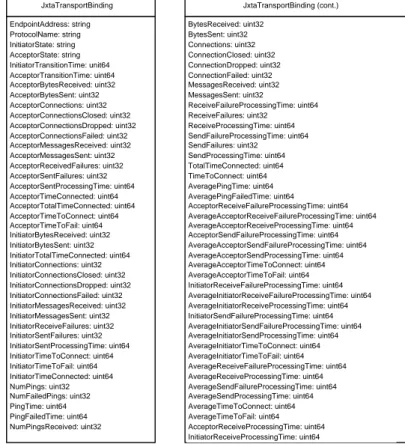
The proposed model for transport service is shown in Figure 4.4. Even though JXTA does not define transport as a service, it behaves in much the same way and hence is best modeled as a service along with its metrics. Transport service is defined for the whole group and is the same in all the peers of that group. The JXTALocalTransportService class inherits from the JXTALocalService class which already has been discussed. Nevertheless the class does not contain the metrics for the service because in the metering project, metrics are defined for each binding with an endpoint. So one can visualize the transport service as being an aggregation of many such bindings in the whole group. The class
JXTATransportBinding models each binding and hence can inherit from ProtocolEndpoint class to get
the endpoint address to which it is bound and the protocol being used.
The metrics defined for transport service are defined in the way of attributes in the
JXTATrans-portBindingclass. These metrics are shown in Figure 4.5. The attributes define things like the number
of bytes received, connections made and so on. The metrics can be separated into acceptor met-rics and receiver metmet-rics. Finally as a combination of both the metmet-rics are also defined. This class is responsible for making up the transport service. Another important modeling detail is that the transport service uses JXTA endpoint in order to transmit data and which is modeled by the relation TransportUsesEndpoint.
1
TransportUsesEndpoint
1
LocalP2PService
JxtaLocalService
JxtaLocalTransportService
(See Jxta model (Communication))
JxtaEndpoint
1
JxtaTransportBinding ProtocolEndpoint (See Core and Networks Model (Protocol Endpoints))
TransportServiceComponent
*
1
Figure 4.4: The transport service model
4.3.2 JXTA endpoint service model
The endpoint service in JXTA is one of the core services in the sense that it implements the endpoint protocol which is a must for any peer running on JXTA. So an evaluation of the endpoint service becomes very important and the model to do that is represented in Figure 4.6. As already discussed, each peer binds to a particular endpoint and so does the endpoint service running on a particular peer. For each endpoint service we can link it to a particular endpoint. So the metrics that monitor the state of the endpoint are put in the JXTAEndpoint class of the communication model. These metrics could have also been a part of the endpoint service model but it would imply the same thing, so it was better to define them in the endpoint class itself.
In the endpoint service model, the JXTALocalEndpointService class is the one that models the endpoint service running on a peer. Since each peer runs the endpoint service locally, we can inherit from the JXTALocalService superclass. The endpoint service from the model has three types of metrics:
• inbound metrics; • outbound metrics; • propagation metrics.
Based on this already existing classification of metrics, we have defined the classes separately to make up the whole endpoint service. It is also important to note the fact about JXTAHandlers in the context of endpoint service. As shown in Figure 4.6, two types of metric classes are inherited from the JXTAHandler class which we will discuss in brief. The description of the classes is what follows in this section.
JXTAInbound class
The JXTAInbound class defines attributes to represent the inbound metrics for the endpoint service. The detailed class diagram with all the attributes is represented in Figure 4.7. In the endpoint service, this class represents the handlers for services that are registered to receive messages through the particular endpoint service. So the JXTAInbound class is inherited from the JXTAHandler class of the service model. It is dynamically instantiated for each service that receives messages via this endpoint service. The class has attributes that give the service name for which it acts as the handler and also the other details about messages received. By inheriting from the JXTAHandler class, we were able to properly model the metrics as a part of the endpoint service but related to the services that receive the message.
EndpointAddress: string ProtocolName: string InitiatorState: string AcceptorState: string InitiatorTransitionTime: unit64 AcceptorTransitionTime: uint64 AcceptorBytesReceived: uint32 AcceptorBytesSent: uint32 AcceptorConnections: uint32 AcceptorConnectionsClosed: uint32 AcceptorConnectionsDropped: uint32 AcceptorConnectionsFailed: uint32 AcceptorMessagesReceived: uint32 AcceptorMessagesSent: uint32 AcceptorReceivedFailures: uint32 AcceptorSentFailures: uint32 AcceptorSentProcessingTime: uint64 AcceptorTimeConnected: uint64 AcceptorTotalTimeConnected: uint64 AcceptorTimeToConnect: uint64 AcceptorTimeToFail: uint64 InitiatorBytesReceived: uint32 InitiatorBytesSent: uint32 InitiatorTotalTimeConnected: uint64 InitiatorConnections: uint32 InitiatorConnectionsClosed: uint32 InitiatorConnectionsDropped: uint32 InitiatorConnectionsFailed: uint32 InitiatorMessagesReceived: uint32 InitiatorMessagesSent: uint32 InitiatorReceiveFailures: uint32 InitiatorSentFailures: uint32 InitiatorSentProcessingTime: uint64 InitiatorTimeToConnect: uint64 InitiatorTimeToFail: uint64 InitiatorTimeConnected: uint64 NumPings: uint32 NumFailedPings: uint32 PingTime: uint64 PingFailedTime: uint64 NumPingsReceived: uint32 JxtaTransportBinding BytesReceived: uint32 BytesSent: uint32 Connections: uint32 ConnectionClosed: uint32 ConnectionDropped: uint32 ConnectionFailed: uint32 MessagesReceived: uint32 MessagesSent: uint32 ReceiveFailureProcessingTime: uint64 ReceiveFailures: uint32 ReceiveProcessingTime: uint64 SendFailureProcessingTime: uint64 SendFailures: uint32 SendProcessingTime: uint64 TotalTimeConnected: uint64 TimeToConnect: uint64 AveragePingTime: uint64 AveragePingFailedTime: uint64 AcceptorReceiveFailureProcessingTime: uint64 AverageAcceptorReceiveFailureProcessingTime: uint64 AverageAcceptorReceiveProcessingTime: uint64 AcceptorSendFailureProcessingTime: uint64 AverageAcceptorSendFailureProcessingTime: uint64 AverageAcceptorSendProcessingTime: uint64 AverageAcceptorTimeToConnect: uint64 AverageAcceptorTimeToFail: uint64 InitiatorReceiveFailureProcessingTime: uint64 AverageInitiatorReceiveFailureProcessingTime: uint64 AverageInitiatorReceiveProcessingTime: uint64 InitiatorSendFailureProcessingTime: uint64 AverageInitiatorSendFailureProcessingTime: uint64 AverageInitiatorSendProcessingTime: uint64 AverageInitiatorTimeToConnect: uint64 AverageInitiatorTimeToFail: uint64 AverageReceiveFailureProcessingTime: uint64 AverageReceiveProcessingTime: uint64 AverageSendFailureProcessingTime: uint64 AverageSendProcessingTime: uint64 AverageTimeToConnect: uint64 AverageTimeToFail: uint64 AcceptorReceiveProcessingTime: uint64 InitiatorReceiveProcessingTime: uint64 JxtaTransportBinding (cont.)
Figure 4.5: The detailed transport service classes
JXTAPropagate class
The JXTAPropagate class is very similar to the JXTAInbound class. It is also instantiated for each service that needs to propagate messages. In this case the attributes represent the way messages are not received but propagated. This is the only difference between the two classes else the way they are modeled is almost similar. This class also inherits from the JXTAHandler superclass. The detailed class diagram presenting all the attributes is shown in Figure 4.7.
The endpoint service is made up of many such JXTAInbound and JXTAPropagate objects for each of the different services that rely on the endpoint service. An example of such a service is the pipe service. The JXTAEPInboundDependency class and the JXTAEPPropagateDependency are shown in Figure 4.12. These classes relate the way endpoint service is formed or composed of the handlers. JXTAOutbound class
In JXTA endpoint service, messages are sent to particular destination addresses using an endpoint. So the outbound metrics are defined per destination endpoint address. The JXTAOutbound class is used to model the outbound metrics. The class inherits from the ProtocolEndpoint class of the core CIM model. This is done in order to represent the fact that the outbound metrics are for a particular destination endpoint. So a composition of many instances of the JXTAOutbound class makes up the outbound part of the endpoint service. The detailed class diagram with all the attributes is shown in Figure 4.7. The attributes in the class represent the metrics related to messages that are being sent
(See Jxta Model (Service Handler model))
JxtaLocalService
JxtaEPInboundDependency
1
(See Jxta Model (Service Handler model))
JxtaHandler
JxtaLocalEndpointService JxtaInbound JxtaPropagate
ProtocolEndpoint (See Core and Networks Model (Protocol Endpoints))
JxtaOutbound JxtaEPOutboundComponent
*
1 JxtaEPPropagateDependency 1 1*
*
Figure 4.6: The endpoint service model
to the destination endpoint using the endpoint service under discussion.
So the endpoint service is composed of three kinds of metrics which all have been modeled and proper relationships were established between these classes and the endpoint service as a whole.
4.3.3 JXTA resolver service
Resolver service, one of the two core services of the JXTA, implements the Peer Resolver Protocol. The model that we propose for the resolver service is represented in Figure 4.8. As discussed in the previous chapter, the resolver service is used to handle queries and responses. It also handles
the SRDI2
queries and responses for rendezvous peers. The JXTALocalResolverService class models the resolver service of JXTA and is inherited from JXTALocalService class since resolver service runs for each peer locally. The attributes defined in this class are shown in Figure 4.9. These attributes represent the overall view of the resolver service in a sense that it gives the total number of queries that were not processed and so on. The finer metrics for the resolver service can be classified into two types:
• Query Handler Metrics • SRDI Handler Metrics
The resolver service is used to propagate or send queries and receive responses on behalf of other services like the discovery service, pipe service etc. So in order to model the metrics properly, we used the same approach as in endpoint service being that of handlers.
JXTAQueryHandler class
The JXTAQueryHandler class inherits from the JXTAHandler class so as to represent the fact that query metrics are defined for each service that uses the resolver to send queries and receive responses. The detailed class diagram with its attributes is shown in Figure 4.9. The attribute HandlerName gives the service name for which this class is instantiated since it uses the resolver service. Another point
2
EndpointStartTime: Date EndpointUpTime: uint64 InvalidIncomingMessage: uint32 NoListenerForIncomingMessage: uint32 ErrorProcessingIncomingMessage: uint32 NoDestinationAddressForIncomingMessage: uint32 NoSourceForDemuxMessage: uint32 DiscardedLoopbackDemuxMessage: uint32 IncomingMessageFilteredOut: uint32 IncomingMessageSentToEndpointListener: uint32 DemuxMessageProcessed: uint32 JxtaEndpoint NumOutboundQueued: uint32 NumOutboundDropped: uint32 TimeToDropOutbound: uint64 NumOutboundDeQueued: uint32 TimeInOutboundQueue: uint64 NumOutboundProcessed: uint32 TimeToProcessOutbound: uint64 NumOutboundFailed: uint32 TimeOutboundToFail: uint64 AverageTimeInOutboundQueue: uint64 AverageOutboundDropTime: uint64 AverageOutboundProcessTime: uint64 JxtaOutbound ServiceName: string ServiceParameter: string NumInboundQueued: uint32 NumInboundDropped: uint32 TimeToDropInbound: uint64 NumInboundDeQueued: uint32 TimeInInboundQueue: uint64 NumInboundProcessed: uint32 TimeToProcessInbound: uint64 AverageTimeInInboundQueue: uint64 AverageInboundDropTime: uint64 AverageInboundProcessTime: uint64 JxtaInbound ServiceName: string ServiceParameter: string NumPropagations: uint32 NumPropagatedTo: uint32 AverageNumTransports: uint32 NumFilteredOut: uint32 NumErrorsPropagated: uint32 PropagationTime: uint64 AveragePropagationTime: uint64 JxtaPropagate
Figure 4.7: The Detailed Endpoint Service Classes
(See Jxta Model (Service Handler model))
JxtaLocalService
JxtaQueryHandlerDependency
(See Jxta Model (Service Handler model))
JxtaHandler
JxtaLocalResolverService JxtaQueryHandler JxtaSrdiHandler
JxtaSrdiHandlerDependency
1
1
*
*
Figure 4.8: The resolver service model
is that many such handlers can be registered in the resolver service for each service that needs the resolver. This is indicated by the JXTAQueryHandlerDependency relation class. Finally we can say that query metrics are defined per handler and also modeled in the same way with handlers being interfaces for higher level services.
JXTASrdiHandler Class
The JXTASrdiHandler class also inherits from the JXTAHandler class of the service model. This class is very much similar to the JXTAQueryHandler class. The only difference is that this class contains metrics related to SRDI and not general queries. SRDI is an algorithm by which JXTA makes the discovery of resources faster by using a rendezvous super peer network. The detailed class diagram and attributes are shown in Figure 4.9. In this figure also the HandlerName attribute behaves the same way giving the service that uses resolver to send and receive SRDI messages.
4.3.4 JXTA Rendezvous Service
The model that we propose for the rendezvous service is shown in Figure 4.10. The
HandlerName: string Registered: boolean Numresponses: uint32 ResponseProcessingTime: uint64 AverageResponseProcessingTime: uint64 ResponseTime: uint64 AverageResponseTime: uint64 NumResponsesErrors: uint32 NumQueries: uint32 NumQueriesRepropagated: uint32 QueryProcessingTime: uint64 AverageQueryProcessingTime: uint64 NumQueryErrors: uint32 NumQueriesSentInGroup: uint32 NumQueriesSentViaWalker: uint32 NumQueriesSentViaUnicast: uint32 NumErrorsSendingQueries: uint32 NumErrorsPropagatingQueries: uint32 NumResponsesSentInGroup: uint32 NumResponsesSentViaWalker: uint32 NumResponsesSentViaUnicast: uint32 NumErrorsSendingResponses: uint32 NumErrorsPropagatingResponses: uint32 NumQueriesSent: uint32 NumQuerySendErrors: uint32 NumResponsesSent: uint32 NumResponsesSendErrors: uint32 JxtaQueryHandler NumInvalidSrdiMessages: uint32 NumSrdiMessagesToUnknownHandler: uint32 NumberInvalidResponses: uint32 NumberResponsesToUnknownHandler: uint32 NumberInvalidQueries: uint32 NumberQueriesToUnknownHandler: uint32 JxtaLocalResolverService HandlerName: string Registered: boolean NumProcessed: uint32 NumberErrorsWhileProcessing: uint32 NumToUnregisteredHandler: uint32 TotalProcessTime: uint32 NumMessagesSentViaWalker: uint32 NumMessagesSentViaUnicast: uint32 NumErrorsSendingMessages: uint32 NumErrorsPropagatingMessages: uint32 JxtaSrdiHandler
Figure 4.9: The detailed resolver service classes
class as it runs on each peer that uses the service. The detailed class diagram and its attributes are shown in Figure 4.11. This class gives an overall idea about the state of the service running on the peer. It has attributes which give the state in which the peer is currently (edge or rendezvous). Then there are attributes to give the number of transitions between states and counters about the number of messages that are propagated. Thus this class gives an overview of the service.
The rendezvous service is active is two cases: • When the peer acts as a rendezvous
• When the peer behaves as a client to another rendezvous peer
Thus for this reason, we designed the model in such a way so as to separate the model to have the client side metrics as well as the rendezvous side metrics. It is clear from the metering model that metrics of the two types are maintained by the service. The metrics of the first kind are represented in Figure 4.10 by the JXTARendezvous class. This represents the rendezvous side metrics for a connection between the rendezvous and a client. It has the attributes like the peer ID of the client and the state of the peer. Then also the metrics like number of connections established between them is noted down by some attributes. So in all it represents the information that is maintained by the client about the rendezvous. The detailed class diagram and attributes are shown in Figure 4.11. Another important point that needs to be stressed is the super class from which the class it is inherited. As designed in the model it inherits from the EnabledLogicalElement class of the CIM core model. This is done because there were no other subclasses of the EnabledLogicalElement class that could have been used to satisfy the purpose. Thus is was best suited to inherit it from the EnabledLogicalElement class.
The other class JXTARendezvousClient, is similar to the previous class discussed but only different in the sense that it gives the client side metrics. It can be better explained in the following manner that this class contains attributes that give information about the particular connection of the client to the rendezvous. These attributes are defined per client connection to the rendezvous. These are the metrics defining the connection by the particular client to the rendezvous. Metrics define various things like the lease time, number of connections made and so on. This architecture is based on the
(See Jxta Model (Service Handler model))
JxtaLocalService
1
JxtaLocalRendezvousService JxtaRendezvous JxtaRendezvousClient
JxtaRendezvousComponent
1
1
*
*
(See Core Model)
EnabledLogicalElement
JxtaRendezvousClientComponent
Figure 4.10: The rendezvous service model
metering model itself. So the overall model depicts the rendezvous service quite satisfactorily. The attributes of the JXTARendezvousClient and shown in Figure 4.11.
State: string TransitionTime: Date Egde: boolean Rendezvous: boolean EdgeStartTime: Date TotalEdgeTime: uint64 NumEdgesTransitions: uint32 RendezvouStartTime: Date TotalRendezvousTime: uint64 NumRendezvousTransitions: : uint32 NumReceivedProcessedLocally: uint32 NumReceivedRepropagatedInGroup: uint32 NumReceivedInvalid: uint32 NumReceivedDead: uint32 NumReceivedLoopback: uint32 NumReceivedDuplicate: uint32 TotalReceivedUndelivered: uint32 TotalReceived: uint32 NumPropagated: uint32 NumFailedPropagating: uint32 NumRepropagated: uint32 NumFailedRepropagating: uint32 NumPropagatedToPeers: uint32 NumFailedPropagatingToPeers: uint32 NumPeersPropagatedTo: uint32 NumPropagatedInGroup: uint32 NumPropagatedToNeighbors: uint32 NumWalks: uint32 NumFailedWalks: uint32 NumWalkedToPeers: uint32 NumFailedWalkedToPeers: uint32 NumPeersWalkedTo: uint32 TimeAsEdge: uint64 TimeAsRendezvous: uint64 JxtaLocalRendezvousService PeerId: string State: string TransitionTime: Date Lease: uint64 BeginConnectionTime: uint64 Connected: boolean Connecting: boolean TimeConnected: uint64 Disconnected: boolean DisconnectTime: uint64 NumConnectionsBeguns: uint32 NumConnectionsEstablished: uint32 NumConnectionsRefused: uint32 TotalTimesToConnect: uint64 LastLeaseRenewalTime: uint64 NumLeaseRenewals: uint32 NumDisconnects: uint32 TotalTimeConnected: uint64 TimeConnectionEstablished: Date JxtaRendezvous PeerId: string State: string TransitionTime: Date Connected: boolean TimeConnected: uint64 TimeConnectionEstablished: Date Disconnected: boolean DisconnectTime: uint64 Lease: uint64 LastLeaseRenewalTime: uint64 NumConnects: uint32 NumLeaseRenewals: uint32 NumDisconnects: uint32 NumConnectionsRefused: uint32 NumErrorsAddingClient: uint32 NumUnableToRespond: uint32 TotalTimeConnected: uint64 JxtaRendezvousClient
Figure 4.11: The detailed rendezvous service classes
The dependency relational classes used in the models and not previously defined are shown in Figure 4.12. Similarly the composition relational classes used are represented in Figure 4.13.
Finally we need to mention that only these four services have been modeled by us because the JXTA MMP defines metrics for these four only till date. When the metrics for the other services would be defined then one can easily incorporate that in the existing model. This would just require to model the other services as they would be defined in due time by the JXTA community. So in this chapter, we gave the description of all the models and their classes with justification as to why they are modeled in the way they are. So at the end of it, we are now ready with a satisfactory information
Dependency
Antecedent: ref ManagedElement {key, *} Dependent: ref ManagedElement {key, *}
Antecedent: ref ServiceAccessPoint {*} Dependent: ref ServiceAccessPoint {*} SAPSAPDependency
Antecedent: ref Service {*} Dependent: ref ServiceAccessPoint {*}
ServiceAccessBySAP
Antecedent: ref P2PService {1} Dependent: ref P2PServiceAccessPoint {1..*}
P2PServiceAccessBySAP
Antecedent: ref JxtaLocalService {1} Dependent: ref JxtaHandlers {1}
JxtaHandlerForService Antecedent: ref JxtaInbound {*}
Dependent: ref JxtaLocalEndpointService {1} JxtaEPInboundDependency
Antecedent: ref JxtaPropagate {*} Dependent: ref JxtaLocalEndpointService {1}
JxtaEPPropagateDependency
Antecedent: ref JxtaQueryHandler {*} Dependent: ref JxtaLocalResolverService {1}
JxtaQueryHandlerDependency
Antecedent: ref JxtaSrdiHandler {*} Dependent: ref JxtaLocalResolverService {1}
JxtaSrdiHandlerDependency
ProvidesEndpoint (See Core Model)
Antecedent: ref JxtaLocalTransportService {1} Dependent: ref JxtaEndpoint {1}
TransportUsesEndpoint
Figure 4.12: The dependency relationships
model to proceed with. The result is quite satisfactory because all the options were tried out before coming down the final solution of each separate model. Thus we can now move on to the architecture and protocol part of the management model.
Component
GroupComponent: ref ManagedElement {key, *} PartComponent: ref ManagedElement {key, *}
TransportServiceComponent GroupComponent: ref JxtaLocalTransportService {1} PartComponent: ref JxtaTransportBinding {*}
JxtaEPOutboundComponent GroupComponent: ref JxtaLocalEndpointService {1} PartComponent: ref JxtaOutbound {*}
JxtaRendezvousComponent GroupComponent: ref JxtaLocalRendezvousService {1} PartComponent: ref JxtaRendezvous {*}
JxtaRendezvousClientComponent GroupComponent: ref JxtaLocalRendezvousService {1} PartComponent: ref JxtaRendezvousClient {*}
Chapter 5
Implementation of the JXTA
management information model
In the previous chapter, we discussed the information model that was designed for managing the JXTA P2P network. The model handled the various domains such as peers, peergroups, topology, pipes and all the services for which JXTA has metrics defined. After the design of the model the next part of the work was to implement the model.
Instead of implementing the whole architecture of a fully working manager and client peers, we developed a small application that enables one peer to access the metrics of another peer. Based on this prototype, the application can be enhanced to make a proper management application in order to monitor the JXTA P2P network and peers in it.
The implementation of the model can be basically divided into two parts:
• In the first part, it requires to deploy a management agent on each peer that will collect all the metrics defined for each of the services and other domains. This agent would be local to the peer and collect the monitor information from the JXTA platform with metering on.
• In the second part, it requires to develop a protocol and an application based on this protocol by which a manager can access all the data of a peer from the agent deployed on the peer. Hence by this way the manager can have an overall idea about the network and peers.
5.1
Deployment of an Agent
In this section, we present the agent that will run on each peer and its implementation. For the
implementation of the agent the middleware selected was JMX1
of Sun Microsystems2
. This is due to the simple reason that JMX is one of the standard available solutions for the management of Java objects. Thus it becomes easier and also more powerful to use JMX for the implementation of the agent to be run on each peer.
5.1.1 JMX - Java Management Extensions
JMX defines architecture for software and network management in Java programming language. The important terms that are used in the context are:
1
Java Management Extensions
2
www.java.sun.com
MBean Interface: This interface needs to be first defined for the Java object that wants to be managed and then the class implements this interface [9]. The interface defines which attributes and operations are to be exposed for management. The naming convention of the methods and attributes is very important as it is from where the JMX agent will realize which attributes to expose and which not.
JMX Agent: The agent is via which the objects are managed. The MBeans which are registered with the agent can be managed through JMX. There are also adaptors like the HTML adaptor with which one can directly view the attributes of the objects being managed and their values. These adaptors need to be registered in the agent.
This was just a very brief idea of the important components that have been used in the implemen-tation and hence need to be looked into first.
5.1.2 Agent Implementation
In the context of JXTA and the model that we designed, the agent that runs on each peer needs to register the objects as soon as they are formed. For this purpose Standard MBeans [9] are sufficient. In order to dynamically register objects in the agent, the first thing would be to start the agent as soon as the peer boots and run it in the background. For this purpose, initially the idea was the start the agent by a new command in the shell. But this again had its drawbacks in the sense that shell is not a part of the platform and may not be used at all by some peers. So to start running the agent for all kinds of peers it was important to integrate the agent with the platform itself. For this purpose, we put the code to start the agent in the class which starts the platform namely Boot. Another point that relates with the agent is that the Agent class is where the server attribute is defined and hence it was made static so that all the MBeans would be registered with the same server.
So with the agent running in the background from the beginning, the next step consists in register-ing the Java objects. The objects to be registered are the ones that are part of the model presented in the previous chapter. Once these objects are registered, one can view the metrics using a HTML adap-tor. So following are the details about all the objects defined in the model that would be registered with the agent.
JXTA Peer
JXTA does not define any specific class for a peer, rather a peer and its attributes are obtained from
PeerAdvertisementclass. This does not help the cause since a peer advertisement maybe created many
a times and will be registered that many times resulting in duplicate MBeans. Thus the name of the object becomes important in this case. So to help the manager, the peers are registered under the following domain name - [”peergroupID”:Type = Peer, PeerName = ”name”, PeerID = ”id”]. By this the domain becomes the peer group and hence all the peers are registered under the group. It gives an idea about the group as a whole. The new interface of PeerAdvMBean was added and changes were made in the PeerAdv class to implement the interface as well as register the peer advertisement. Since the name of the object remains the same, the peer advertisements are not registered many times but just once.
JXTA Peergroup
Similar to the peer, there are no concrete classes for defining a peergroup and so again to register groups we have used peergroup advertisements. Going along the same lines as for a peer, the duplicacy