HAL Id: inria-00171137
https://hal.inria.fr/inria-00171137v2
Submitted on 12 Sep 2007HAL is a multi-disciplinary open access archive for the deposit and dissemination of sci-entific research documents, whether they are pub-lished or not. The documents may come from teaching and research institutions in France or abroad, or from public or private research centers.
L’archive ouverte pluridisciplinaire HAL, est destinée au dépôt et à la diffusion de documents scientifiques de niveau recherche, publiés ou non, émanant des établissements d’enseignement et de recherche français ou étrangers, des laboratoires publics ou privés.
Antoine Honoré, Ouassila Labbani, Sébastien Le Beux, Philippe Marquet,
Eric Piel, Julien Taillard, et al.
To cite this version:
Rabie Ben Atitallah, Pierre Boulet, Arnaud Cuccuru, Jean-Luc Dekeyser, Antoine Honoré, et al.. Gaspard2 UML profile documentation. [Technical Report] RT-0342, INRIA. 2007, pp.45. �inria-00171137v2�
a p p o r t
t e c h n i q u e
0249-0803 ISRN INRIA/R T --0342--FR+ENG Thème COMGaspard2 UML profile documentation
Rabie Ben Atitallah — Pierre Boulet — Arnaud Cuccuru — Jean-Luc Dekeyser — Antoine Honoré — Ouassila Labbani — Sébastien Le Beux — Philippe Marquet — Éric Piel —
Julien Taillard — Huafeng Yu Email: [email protected]
N° 0342
Unité de recherche INRIA Futurs Parc Club Orsay Université, ZAC des Vignes, 4, rue Jacques Monod, 91893 ORSAY Cedex (France)
Téléphone : +33 1 72 92 59 00 — Télécopie : +33 1 60 19 66 08
Rabie Ben Atitallah , Pierre Boulet , Arnaud Cuccuru , Jean-Luc Dekeyser , Antoine Honoré , Ouassila Labbani , Sébastien Le Beux , Philippe Marquet , Éric Piel , Julien Taillard , Huafeng
Yu
Email: [email protected]
Thème COM — Systèmes communicants Projet DaRT
Rapport technique n° 0342 — September 2007 — 45 pages
Abstract: This document describes the current UML profile of Gaspard2. This profile extends the UML semantics to allow the user to describe a SoC (System-on-Chip) in three steps: the application (behavior of the Soc), the hardware architecture, and the association of the application to the hardware architecture. The application is represented following a data flow model, but additional mechanisms permit the usage of control flow on those applications. In addition to those notions, the profile contains a package introducing factorization mechanisms to enable the compact description of massively parallel and repetitive systems.
pour permettre à l’utilisateur de décrire un SoC (système-sur-puce) en trois étapes : l’application (le comportement du SoC), l’architecture matérielle, et l’association de l’application sur l’architecture. L’application est représentée selon un modèle de flux de données, mais des mécanismes supplémentaires permettent l’usage d’un flux de contrôle sur ces applications. En complément à ces notions, le profil contient un paquetage introduisant des mécanismes de factorisation rendant possible la description compacte de systèmes massivement parallèles répétitifs.
Mots-clés : Gaspard, UML, profil, système-sur-puce, parallélisme, parallélisme de données, co-modélisation
Introduction
This document describes the current UML2 profile of Gaspard2 [4]. This profile extends the UML2 semantics [3] to allow the user to describe a SoC (System-on-Chip) in three steps: the application (behavior of the Soc), the hardware architecture, and the association of the application to the hardware architecture. This is a refinement of the profile presented previously in the thesis of Arnaud Cuccuru [2].
Chapter 1
Packages overview
1.1
Overview
Figure 1.1: Packages overview
1.2
Description
Here is a short description of the seven packages that compose the Gaspard2 profile. Each one will be explained in details in the following chapters.
multiDimMultiplicity
The multiDimMultiplicity package introduces the concept of multi-dimensional multiplicity explained in [2]. This is an extension of the UML2 multiplicity attribute of the metaclass MultiplicityElement.
In place of just putting one integer, we insert a vector of integers that gives the size of each dimension. This package is not directly written in the profile because we use the multiplicity of UML2 as a string value to simplify Gaspard2 models writing.
component
The component package gives the basis of Gaspard2 component behaviour and their interconnections. This package introduces the elementary component (view as a black box), the hierarchical component and the repetitive component. UML2 metaclasses are specialized and rules are given. Most of Gaspard2 elements are based on the UML2 Component metaclass with its ports.
factorization
The factorization package represents Array-OL concepts that perform array computing and model factorization.
hardwareArchitecture
This package contains all the components that describe a hardware architecture in Gaspard2. According to the factorization package, the hardwareArchitecture package allows powerful and compact modeling of regular and repetitive architectures, such as a multiprocessor architecture. This package is still under development.
application
The application package allows the expression of intensive signal processing tasks, and powerful expressions of data dependences between tasks.
control
The control package introduces the concept of automaton in Gaspard2. For now, it is only used with application components.
association
The association package defines relations between application and hardware components. In particular, it allows to specify the way to associate data and task components with hardware components.
Chapter 2
Package Component
2.1
Overview
The Component package provides some basic extensions to the UML2 component model. It also provides strong guidelines and shortcuts in order to make it more user friendly to handle:
• Systematic identification of interaction points trough the definition of ports,
• Components internal structure descriptions through the use of composite structure diagrams, • Systematic use of delegation connectors to relate the externally visible boundary of a component
to its internal parts,
• Simplification of the ports typing mechanism, with an explicit direction information.
• A specific parameter model, more suited to our needs than the classical UML template mechanism. The extensions are displayed on Figure 2.1. The main extension introduced is the GaspardComponent abstract stereotype. It does not carry any particular semantics, but only provides a context for the definition of common mechanisms and constraints related to the Gaspard component model. This stereotype will be refined in the application and hardwareArchitecture packages. The GaspardPort abstract stereotype (and its In, Out refinements) is introduced to simplify the way to type ports, and specify its direction. We will see in the corresponding sections that there is a systematic way to translate models expressed with this “syntaxic sugar” to more academic UML models. Finally, the
Parameter stereotype is introduced to provide a more flexible way to define parameterized components
than the classical UML template mechanism.
The name of every component in a Gaspard model must conform to the UML convention, that is begin with an uppercase letter (english only) and then any alpha-numerical character. This is mainly to facilitate the transformation of name into conformant names in the transformation target languages.
2.2
Description
2.2.1 GaspardComponent
The GaspardComponent stereotype is the main extension introduced in this package. It is abstract and does not carry any particular semantics, but only provides a context for the definition of common mechanisms and constraints related to the Gaspard component model. All Gaspard models (either Application or Hardware Architecture models) are component based.
This stereotype applies to the UML2 Component metaclass. The introduction of this stereotype enables to specify clear construction rules and ways of using UML components to make them Gaspard
compatible. Among this constraint, the Gaspard component model imposes a systematic use of ports as interaction points. It means that all connections expressed between components (or more precisely between parts typed by components) will be done through their ports. Moreover, every
GaspardComponent is potentially hierarchical (except for the ElementaryComponent refinement), and
the Gaspard component model imposes that the topology of the internal structure is specified in an unambiguous way: the description of the internal structure of a component must be done through the use of composite structure diagrams. Finally, the internal parts of a component must be explicitly related to the ports on the boundary of the containing component. This implies the systematic use of delegation connectors expressed between the ports of the concerned internal parts, and the ports on the boundary of the containing component.
Note that this stereotype is abstract, and can not be applied directly. This stereotype will be refined in the application and hardwareArchitecture packages.
Extension
This stereotype applies to the Component metaclass. Attributes
No additional attributes are defined for this stereotype. Constraints
• A Component stereotyped GaspardComponent can only contain parts typed by a Component stereotyped GaspardComponent. This is expressed by this OCL constraint:
inv: self.part->exists(p|p.stereotype->exists(name=’GaspardComponent’))
• A Component stereotyped GaspardComponent can only have ports stereotyped GaspardPort. This is expressed by this OCL constraint:
inv: self.OwnedPort.stereotype->forAll(name=’GaspardPort’)
• Connections between parts of a Component stereotyped GaspardComponent can only be expressed between their ports.
• When connections are expressed between ports, the ports should have compatible types. • When connections are expressed between ports, then one of the port should be an In, and the
other an Out.
• When delegation connections are expressed between ports on the boundary of the Component and parts contained in its structure, the source and target ports should have the same direction. 2.2.2 MainInstance
This stereotype generalizes the InstanceSpecification metaclass. It is applied to an instance of component which is the root of the application or the architecture. This allows to indicate which is the starting point of execution of an application or the container of an architecture. This instance does not have any port.
Generalization
Constraints
One and only one InstanceSpecification must be specified for the application in a model, as well as for the architecture.
2.2.3 ElementaryComponent
This stereotype extends the GaspardComponent stereotype. It is applied to a component which is seen as black box. It means concretely that this component does not have an internal structure description, or at least that the internal structure description will not be specified in the UML model.
During the deployment, an “implementation” will have to be associated for Gaspard to be able to implement the model.
Generalization
This stereotype extends the GaspardComponent stereotype. Attributes
No additional attributes are defined for this stereotype. Constraints
A component stereotyped ElementaryComponent does not have any internal structure. This is expressed by the following OCL constraint:
inv: self.part->select(stereotype->exists(name=’GaspardComponent’))->size()=0
2.2.4 GaspardPort
The GaspardPort abstract stereotype applies to the Port metaclass. It is introduced to simplify the way to type ports, and specify their direction. In classical UML models, ports own provided and required interfaces, specifying the interactions that can occur between these ports and the environment of the component. These interactions are basically message oriented, though the emission/reception of operation calls or signals. The provided and required interfaces of a port describe these potential interactions. A required interface is usually seen as the set of services a component may require to its environment, whereas a provided interface represents the set of services a component is supposed to provide to its environment.
This message passing direction is not suited to the scope of Gaspard models (either application or hardware architecture), which are more data oriented. With the GaspardPort concept, we propose to avoid the use of interfaces. The type of data transmitted through a port is directly defined through the type property of the Port metaclass. This type must be defined in UML as a DataType (of UML). The multiplicity of the port specifies the shape of the arrays which pass though it. The direction of the port is explicitly specified via the use of the several refinements of GaspardPort (i.e. In, Out).
Note that this mechanism is only a “syntaxic” sugar. The same semantic could be obtained using interfaces carrying only one signal (with one parameter typed by the type of the transmitted data). The direction would be specified by the way the interface is related to the port: Required for an Out semantics (the component is able to emit signals to its environment through this port), Provided for an In semantics (the component is able to receive signals from its environment through this port).
Note also that this stereotype is abstract, and can not be applied directly.
When a port on a GaspardComponenent is not stereotyped, it gets the default meaning that data might flow in either direction. This semantic is not meaningful, and therefore forbidden, on an
ApplicationComponent. However, on a HardwareComponent, this can be to express the fact the a same
connection can be used either to send or receive data. Generalization
This stereotype applies to the Port metaclass. Attributes
No additional attributes defined. Constraints
• When connections are expressed between ports, the ports should have compatible types. • When connections are expressed between ports, then one of the port should be an In, and the
other an Out.
• When delegation connections are expressed between ports on the boundary of the Component and parts contained in its structure, the source and target ports should have the same direction. 2.2.5 Out
The Out stereotype extends the GaspardPort stereotype. It only specifies that the Gaspard port is an Out port. An ApplicationComponent with such a port will send one array of data which after each iteration through this port. Such a port on a HardwareComponent means that on the connection linked to this port, the component will always be an “initiator”, that is will always start any transmition. Generalization
This stereotype extends the GaspardPort stereotype. Attributes
No additional attributes defined. Constraints
No additional constraints defined. 2.2.6 In
The In stereotype extends the GaspardPort stereotype. It only specifies that the Gaspard port is an In port. An ApplicationComponent with such a port will not be run until data has been received on this port. Such a port on a HardwareComponent means that on the connection linked to this port, the component will always be a “target”, that is will never initiate any transmition.
Generalization
This stereotype extends the GaspardPort stereotype. Attributes
Constraints
Chapter 3
Package Factorization
3.1
Overview
Figure 3.1: Concepts of the factorization package
3.2
Description
This package introduces mechanisms that enable to express in a compact way the topologies of relations expressed between multi-dimensional arrays of connectable elements. In this section, these mechanisms are introduced in a generic way. The defined extension set will be concretely used in the application, hardware architecture and association packages, where a particular semantic or interpretation will be given to them.
To see a collection of elements (i.e. an element with a multiplicity, called a MultiplicityElement in the UML2 specification) as a multidimensionnal array of elements, we introduce the Shaped stereotype, which enables to specify the shape (i.e. number of dimensions and size of each dimension) of the collection represented by the multiplicity of the element. In our proposal, this stereotype is concretely used with parts and ports.
A set of extensions is then introduced to enable a compact and non ambiguous specification of the topology of the relations between multidimensionnal arrays of elements. These extensions are based on the LinkTopology abstract stereotype. We basically differentiate two use cases (providing two refinements of the LinkTopology): Relations expressed between elements inside of two separate arrays (Reshape and Tiler), and relations expressed between elements inside of the same array (InterRepetition).
The first set of extensions is basically inspired by the Array-OL data parallel language, and concerns a relation expressed between elements contained in two separate arrays. The mechanism relies on a vector based formalisms, that enable to identify patterns of elements inside of each of the arrays (that we will call source and target pattern to ease explanations), and establish unambiguously relations between elements of a source pattern and elements of a corresponding target patterns. This mechanism will be described in the corresponding sections. The main difference between Reshape and Tiler is that
Tiler is used only with delegation connectors (i.e. connectors expressed between ports on the boundary
of a component, and ports of its internal parts), and can be seen as a Reshape partially specified (i.e. the remaining information could be deduced).
The second set of extensions enables to express relations between elements inside of the same multidimensional array, also using a vector based formalism, through the InterRepetition stereotype. For example, this mechanism enables to express a grid of elements, where each element is connected to neighbours located at south, north, east and west position. Several additional stereotypes (based on the DefaultLink abstract stereotype) are introduced to specify how the default mechanism behaves on the boundaries of the multidimensional array. For example, in the previously introduced grid example, the connections to elements located at north does not exist. The default links enables to specify the connections to take into account in this context.
3.2.1 Shaped
The multiplicity concept of UML enables to give directives concerning the instantiation of the element it is attached to. These directives concern the number of elements that can potentially be instantiated. The multiplicity concept is familiar to UML users. It is defined as an inclusive interval of positive integer values, starting with a lower bound and ending with an upper bound. It defines the set of valid cardinalities for the element it is attached to. In UML, an element with a multiplicity can be seen as monodimensionnal array of elements (in the case where the isOrdered property of the MultiplicityElement is equal to TRUE).
The Shaped stereotype we introduce enables to provide a multidimensionnal view of this collection. The shape : String tagged value enables to specify the shape of this collection (i.e. number of dimensions and size of each dimension). The String value of the shape tag represents a vector of positive integer values, where the number of elements determines the number of dimensions of the array, and where each integer value determines the size of the corresponding dimension.
We allow users of the profile to specify a value only for the shape tag of a Shaped MultiplicityElement, without specifying a value for the multiplicity property of the MultiplicityElement. If both are specified, then the product of the elements of the shape vector must be equal to the value of the multiplicity property.
Note that the use of this stereotype is optional. We allow users of the profile to directly use the multiplicity property of the MultiplicityElement metaclass to specify the shape of the collection.
Generalization
This stereotype applies to the MultiplicityElement metaclass. Attributes
• +shape: String, a string representing a vector specifying the shape of the collection. Constraints
• The vector represented by the shape tag cannot be empty. This constraint can not be expressed in OCL.
• If both a vector is specified for the shape tag and a value is specified for the multiplicity property, the product of the elements of the vector must be equal to the value of the upper bound of the multiplicity. This constraint can not be expressed in OCL.
Optional notation
We allow users to directly specify the shape of a collection using the multiplicity property of the MultiplicityElement, without using the Shaped stereotype.
3.2.2 LinkTopology
In order to take into account modeling of link topologies, we introduce the LinkTopology abstract stereotype. LinkTopology is an optional set of information that can be associated to a connector, between Shaped parts and ports. The LinkTopology does not carry any particular semantics. Semantics will be specified in the context of its three refinements: Reshape, Tiler and InterRepetition. The modulo tagged value is common to the three refinements, and a particular interpretation will be given for this tag according to each refinement.
Note that this stereotype is abstract, and can not be applied directly. Generalization
This stereotype applies to the Connector metaclass. This stereotype is abstract. Attributes
• +modulo: Boolean = false, a common property for each of the refinements of the LinkTopology stereotype. A particular interpretation will be given for each of the refinement.
Constraints
No additional constraints. 3.2.3 Tiler
The Tiler stereotype extends the LinkTopology abstract stereotype. As a consequence it applies to the
Connector metaclass. It also applies to the ConnectorEnd metaclass, in order to use it with Reshape
connectors, as illustrated in the next section.
The Tiler stereotype can be applied directly to connectors only if the connectors are “delegation” connectors, i.e. the connectors relate ports on the boundary of component, and port of an internal part. See section 3.3.1 for more details.
A Tiler is always associated to a repetitionSpace, which is usually the Shape of the inner component linked with it. For each repetition within this repetitionSpace the Tiler links a tile in the array, which is of the size the outer port to the pattern, which is of the size of the inner port. The
Tiler stereotype enables to express in a compact way all the correspondences existing between ends
contained inside the array and the pattern arrays. As a consequence, all the links that will potentially exist at run-time (the term link is used here in its original UML meaning, that is to say an instance of a Connector). The idea is to identify tiles inside the array, and establish relations between points contained in this tile to the pattern (i.e. between potential link ends).
The paving tag of the Tiler stereotype is a String representing a set of vectors. It enables to identify the origin of a pattern inside of the corresponding multidimensionnal array. The number of patterns contained inside of each array is determined by the repetitionSpace. The paving process can be defined as follows: Identifying a pattern origin inside of an array can be seen as an iterative process, where iteration limits are given by the repetitionSpace vector. Each pattern origin is determined by multiplying each index of the repetitionSpace by the paving vectors, adding the origin vector. The origin tag of the Tiler stereotype is then used to define this vector.
From each pattern origin identified with the paving process, the fitting tag of the Tiler stereotype enables to identify the points that belong to this pattern. This set of points define the tile. The patternShape, the shape of the port of the inner component, determines the number of points that belong to a pattern. For the fitting process, each point that belongs to a pattern is determined by multiplying the fitting vectors by each index contained in the repetition space defined by the patternShape tag, adding the origin given by the paving process.
More formally, for a given repetitionSpace, i, 0 ≤ i < pavingLimit, the pattern is composed by the points indexed by the following set:
{origin + paving.i + fitting.j | 0 ≤ j < patternShape} (3.1) if the modulo attribute is equal to false, and by
{origin + paving.i + fitting.j mod shape | 0 ≤ j < patternShape} (3.2) if the modulo tag is equal to true.
One could note that the modulo is not necessary. It is just an simplification for the transformations. Knowing that it is meaning less to access the array outside its dimensions, if the attribute does not exist, it should be considered as always true. One can then detect when the simpler formula is sufficient: if all the value positions are within the array dimensions. As the function is monotonic, it is easily checked by computing the positions of the last point (patternShape − 1) of the last repetition (repetitionSpace − 1), if there are all within the array dimension, the modulo can be considered as false, and the optimized formula used.
Generalization
This stereotype extends the LinkTopology abstract stereotype. It also applies to the ConnectorEnd metaclass.
Attributes
• +origin: String, a String representing a vector (cf Section 3.3.2), used as an origin for the paving process.
• +paving: String, a String representing a matrix (cf Section 3.3.2), used for the paving process (i.e. to identify the origin of each pattern inside of a given multidimensionnal array).
• +fitting: String, a String representing a matrix, used for the fitting process (i.e. to identify points that belong to a given pattern).
• +tiler: InstanceSpecification, related to the optional notation for tilers. Constraints
If the tiler tag is not equal to NULL, then origin, paving and fitting must not be specified. This is expressed by this OCL rule:
inv: (self.taggedValue->select(name=’tiler’ and value<>’NULL’)implies self.taggedValue->exclude(name=’origin’ or name=’paving’ or name=’fitting’)) and (self.taggedValue->select(name=’tiler’ and value=’NULL’)implies self.taggedValue->exclude(name=’tiler’))
Optional notation
The origin, paving and fitting tags can be left empty. The “tiling information” can be specified using the tiler tag, referencing an instance (with proper instance values) of the Tiler class.
3.2.4 Reshape
The Reshape stereotype extends the LinkTopology abstract stereotype. It enables to express complex topologies between parts and ports contained in two separate multidimensionnal arrays. More precisely, a Reshape connector is expressed between Shaped ports of two different Shaped parts. There are as many links as the multiplication of the multiplicity of the port by the multiplicity of its part. The shape of each multidimensional array is considered to be a concatenation of the shape of the ports and the shape of the part. For example, let us consider a port with a shape equal to (3,3), and a owning part with a shape equal to (10,5). Then the global shape of the multidimensionnal array is equal to (10,5,3,3). In fact, the arrays contains all the potential link ends corresponding to an instantiation of the model. See section 3.3.1 for more details.
When the Reshape stereotype is applied, the Tiler stereotype must be applied to each of the connector end. With those two Tilers, the Reshape stereotype enables to express in a compact way all the correspondences existing between ends contained inside the two multidimensionnal arrays. It is strictly equivalent to a component with two ports and a part linked by the two Tilers of the Reshape. The part is an identity elementary component, it outputs the same pattern as it takes in input. The
Shape of the inner part is the repetitionSpace tag of the Reshape, while the Shape of its ports is the
patternShape tag of the Reshape. The Shape of the ports of the component is the Shape of the ports to which the Reshape is connected.
Note that when two connector ends have the same shape, it is allowed to specify a connector between the two ends without using the Reshape stereotype. As described in section 3.3.1, the connector is then interpreted as a one to one connection between the potential link ends contained inside of the two multidimensionnal arrays.
Generalization
This stereotype extends the LinkTopology abstract stereotype. Attributes
• +repetitionSpace: String, a String representing a shape (cf Section 3.3.2), used as a limit for the paving process.
• +patternShape: String, a String representing a shape (cf Section 3.3.2), used as a limit for the fitting process.
Constraints
• For each Tiler connector ends related to a given Reshape connector, the number of vec-tors contained in the paving tag must be equal to the number of integers contained in the repetitionSpace tag. This constraint can not be expressed in OCL.
• For each Tiler connector end related to a given Reshape connector, the number of vectors contained in the fitting tag must be equal to the number of integers contained in the patternShape tag. This constraint can not be expressed in OCL.
• The number of elements contained in a given paving vector must be equal to the number of dimensions of the corresponding connector end (number of dimensions of the part + number of dimensions of the port). This constraint can not be expressed in OCL.
• The number of elements contained in a given fitting vector must be equal to the number of dimensions of the corresponding connector end (number of dimensions of the part + number of dimensions of the port). This constraint can not be expressed in OCL.
3.2.5 InterRepetition
The InterRepetition stereotype extends the LinkTopology abstract stereotype. It is used to describe topologies where relations are expressed in the context of a repetition of a single element, such as in a grid or a cube topology. Each potential instance of a part is connected to other potential instances of the same part. For example, in the context of a toroidal grid, each instance is connected to neighbours located at north, south, east and west position.
The InterRepetition stereotype enables to specify the position of the neighbours of each potential instance of a Shaped part. Each potential instance is implicitly associated to one point of the multidimensionnal array described by the shape of the Shaped MultiplicityElement.
Contrarily to the Reshape stereotype, the shape of the multidimensionnal array corresponds only to the shape of the part. The shape of the port is not taken into account. The repetitionSpaceDependence tag of the InterRepetition stereotype is a String representing a vec-tor of integer values. It describes a translation vecvec-tor on the space of the multidimensionnal array. It identifies the position of a given neighbour. The inherited modulo tag of the InterRepetition stereotype indicates if the translation is applied modulo the size of the multidimensionnal array. If modulo is set to false, some translations can not applied, and the corresponding links will not be created. In this case, it is possible to used DefaultLink connectors (described in the next section) to specify a “default behavior” for the creation of links.
Please note that in Gaspard with differentiate the words dependence, and dependency. While the first one is used in the context of data dependence, dependency is used in the context of object oriented programming and inheritance (used mainly in the association package).
Generalization
This stereotype extends the LinkTopology abstract stereotype. Attributes
• +repetitionSpaceDependence: String, a String representing a vector (cf Section 3.3.2). The
vector is a translation vector on the space of the multidimensionnal array specified by the shape
Constraints
The number of elements contained in the repetitionSpaceDependence vector must be equal to the number of elements contained in the shape of the Shaped part.
When applied on an ApplicationComponent, the modulo tag must be set to false. This is due to the semantic meaning: on an ApplicationComponent, the InterRepetition is considered as a dependence over the time, it is not possible to have the first executed instance dependent on the last executed one. 3.2.6 DefaultLink
The DefaultLink stereotype applies to the Connector metaclass. It is introduced to be used jointly with
InterRepetition connectors which have a modulo tag set to false. The DefaultLink connector is then
“selected” when a “default behavior” has to be defined for the link creation on the boundaries of the shape of the multi-dimensional array. This “default behavior” is needed when the InteRepetition link has one of its connector ends missing (because it is located on the “border” of the iteration space).
A DefaultLink connector is generally also stereotyped Tiler. In this case, the process for determining the topology of the connector is the same as the one described in the Tiler sections, except that the links that will be created are only the ones concerned by the “default behavior” for links creation. The Tiler is executed with the iteration of instance of the component for which the
InterRepetion link failed.
Generalization
This stereotype applies to the Connector metaclass. Attributes
No additional attributes defined. Constraints
At least one ConnectorEnd of a DefaultLink connector must be part of the ConnectorEnds of a
InterRepetition connector.
3.2.7 Tiler class
This class is introduced in order to provide an optional notation for tiling information, as explained in the Tiler section. The guideline to use this optional notation is to define instances of this Tiler class, with proper instance values. This instance can then be referenced by the tiler tag of the Tiler stereotype. If the same tiling information are reused many times, it avoids repeating the definition of the values of the origin, paving, and fitting tags of the Tiler stereotype.
3.3
Syntax and Semantic
3.3.1 Syntax and semantic of plain connectors, tilers, and reshapes
Tilers and reshape cannot be used everywhere. In particular, Tilers, which are a way to express address computation, can only have a meaning within the repetitionSpace of a component. On the opposite, the Reshape have their own repetitionSpace. In this section we will detail the various cases of topology within which connectors can be used and precise their semantics.
For each of the three types of connectors (plain, tiler, reshape), a connector can be either linking two components of the same level (assembly connector) or linking a component and its containing component (delegation connector). This leads to 6 basic topologies.
Plain connectors
A connector with no stereotype linking a part A of shape M from a port of shape N to a port of shape N0 of a part B of shape M0 is only allowed if the shapes M, N and M0, N0 are identical . By identical, it means that the string concatenation of M and N is exactly the same as M0 and N0. For instance a task with M = 4, and N null, could be connected with plain connectors to a task with M0 null and N0 = 4 but not to a task with M0 = 4 and N0= 1. This topology, schematized on Figure 3.2, means that each element of the array M, N is transmitted to the element having the same position in the array M0, N0.
Figure 3.2: Two components connected via a plain assembly connector
A connector with no stereotype linking a part A of shape M from a port of shape N to a port of
shape P of a containing component is only allowed if the shapes M, N and P are identical. This
topology, schematized on Figure 3.3, means that each element of the array M, N is transmitted to the element having the same position in the array P .
Figure 3.3: A part connected via a plain delegation connector to its container Tilers
A connector with the stereotype Tiler linking two parts through ports is not allowed. This construc-tion, schematized on Figure 3.4, would have no meaning, as a Tiler requires to be in the context of a repetitionSpace.
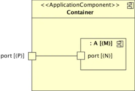
A connector with the stereotype Tiler linking a part A of shape M from a port of shape N to a port of shape P of a containing component is allowed . This topology, schematized on Figure 3.5, means that each element of the pattern N at the iteration M is transmitted to the element the array P according the origin, paving and fitting attributes of the Tiler following this formula (if the moduloattribute is set, otherwise, it is the same formula without modulo) :
Figure 3.4: An illegal syntax: Two components connected via a tiler assembly connector
Figure 3.5: A part connected via a tiler delegation connector to its container Reshapes
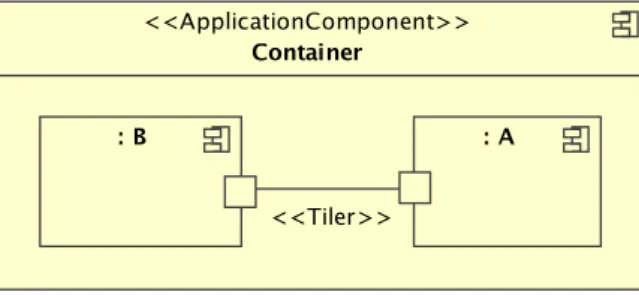
A connector with the stereotype Reshape linking a part A of shape M from a port of shape N to a port of shape N0 of a part B of shape M0 is allowed. This topology, schematized on Figure 3.6, is equivalent to linking them through a identity task (a task which output is identical to the input) with a its ports of shape patternShape in a repetition of repetitionSpace and linked with two tilers having the properties of the two tilers of the reshape.
Figure 3.6: Two components connected via a reshape assembly connector
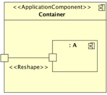
A connector with the stereotype Reshape linking a part A of shape M from a port of shape N to a port of shape P of a containing component is is not allowed. This construction, schematized on Figure 3.7, would have no meaning, as a Reshape has its own repetitionSpace.
Figure 3.8 demonstrates the use of the three types of connectors in various context, with the equivalence of the Reshapes as Tilers in an Application model.
Figure 3.7: An illegal syntax: A part connected via a reshape delegation connector to its container 3.3.2 Vector notations syntax and semantic
Gaspard uses three concepts of derived from the mathematical vectors:
1. The shapes which are an ordered (ordered has the UML meaning: the order is fixed and meaningful) list of non-negative integers, which can be unlimited (expressed by ∼). They are written as (a,b,c). They are used in the Shaped, Reshape, Distribution.
2. The vectors which are an ordered list of integers (positive or negative). They are written as (a,b,c). They are used for the origin of a Tiler, InterRepetition.
3. The matrices which are an ordered list of vectors, each vector representing one row of a math-ematical matrix. They are written as ((a1,a2),(b1,b2),(c1,c2)), equivalent to
a1 a2 b1 b2 c1 c2
They are used for the fitting and paving of a Tiler.
All these three types of vectors contain expressions, where an expression is an abstraction of an integer value. More precisely, these expressions are affine, and potentially reference a parameter defined at the level of the namespace component. For example, a Shaped port can reference a portSize parameter defined on the owning component, with a shape tag specified as follows: shape=(portSize,portSize). 3.3.3 Additional constants
This set of constants is used to simplify the notation of vectors for simple cases:
• ZERO A vector or a matrix with all values set to 0, with the correct size (as many elements as the array has dimensions or computed from array and pattern, or array and repetitionSpace) • ONE A vector with all its value set to 1, with the correct size (as many elements as the array has
dimensions)
• ALL A vector identical to the input and output arrays of a reshape. This is obviously valid only if the input and output arrays have the same shape.
• IDENTITY A square matrix with 1’s on the diagonal and 0’s everywhere else. The matrix dimension is computed according to the array and the pattern (or repetitionSpace). As it has to be square, therefore the number of dimensions of the array must be the same as the number of dimensions of the pattern (or repetitionSpace).
{repetitionSpace = (r), patternShape = (rs)}
Figure 3.8: Equivalence of Reshapes with more basic concepts in an Application model. The first model uses a Reshape to link two repeated components. The second models expresses the same application, in a different way.
Chapter 4
Package HardwareArchitecture
4.1
Overview
The hardwareArchitecture package main objective is to satisfy the growing need of embedded systems designers to model a high level modeling. Using this package, a designer shall be able to dimension material resources and to describe interconnection topology at a coarse grain level. The UML representation is available in the Figure 4.1.
4.2
Description
4.2.1 HardwareComponent
A HardwareComponent is an abstraction of a physical material resource. For such a component it is necessary to specify if it is an ElementaryComponent. A HardwareComponent can be refined as a
Processor, a Communication or a Memory, using stereotypes.
Generalization
This generalizes GaspardComponent. Constraints
A HardwareComponent can only contain HardwareComponent. 4.2.2 Communication
The Communication concept represents a material component describing interconnections between component. The Communication supports data and instruction transaction.
Generalization
This generalizes HardwareComponent. Constraints
A Communication component can only contain Communication components. 4.2.3 IO
IO gives the way the architecture communicates with its environment. Thus, it is allowed to model a
part of the architecture environment. Generalization
This generalizes HardwareComponent. 4.2.4 Sensor
A Sensor is a component which send data to the architecture. They are mainly an abstraction of a real sensor component, like an Analog to Digital Converter (ADC).
Generalization This generalizes IO. 4.2.5 Actuator
A Sensor is a component which send data to the architecture environment. They are mainly an abstraction of a real actuator component, like a Digital to Analog Converter (DAC).
Generalization This generalizes IO.
4.2.6 Memory
The Memory abstract concept express a component offering a data storage capabilities. A Memory can contain instruction or data. They are considered as a slave, since they are not able to initiate communications.
Generalization
This generalizes HardwareComponent. Constraints
A Memory component can only contain Memory components. 4.2.7 RAM
RAM memory only contain ports with the In interface. Thus a RAM component is a hardware resource than can only propose read/write services to its environment.
Generalization
This generalizes Memory. Constraints
A RAM can only contain RAM. 4.2.8 Cache
This concept defines a cache memory abstraction and its controller. A Cache material component has a port with the In interface, providing read/write services to a processor, and a port with the Out interface, offering read service to its environment while a cache miss occurs.
Generalization
This generalizes Memory. Constraints
A Cache can only contain Caches. Semantic
Even if a cache is not directly programmable by a programmer (in the association model, we can not directly place data on cache memory), it is useful to know their capabilities and their organization in order to optimized transferred data bloc.
4.2.9 Processor
The Processor material component represents a resource able to realize computation. They are also able to emit read/write request to their environment, event if it also depends on the associated interface and their orientation (In or Out). In the Gaspard association model, Processor are used to support execution of application component.
Generalization
This generalizes HardwareComponent. Constraints
A Processor can only contain Processor. 4.2.10 ProgrammableProcessor
ProgramableProcessor defines a kind of processor which manipulate one or several instruction set. A ProgramableProcessor can represent a General Purpose Processor (GPP) or a Digital Signal Processor
(DSP).
Generalization
This generalizes Processor. Constraints
A ProgrammableProcessor can only contain ProgrammableProcessor. 4.2.11 HardwareAccelerator
HardwareAccelerator represents an Application Specific Integrated Circuit (ASIC), corresponding to a
circuit specialized for a particular function. Generalization
This generalizes Processor. Constraints
Chapter 5
Package Application
5.1
Overview
Figure 5.1: Application components
5.2
Description
5.2.1 ApplicationComponent
An ApplicationComponent represents a computing component on the application side. For such a component it is necessary to also specify if it is an ElementaryComponent or not.
Generalization
This generalises GaspardComponent. Constraints
An ApplicationComponent can only contain ApplicationComponents. 5.2.2 ArrayProducer
A physical sensor is modeled as an ArrayProducer in the application level. In this level, only the characteristic of multidimensional array production of a sensor is considered, i.e. an ArrayProducer component produces infinite multidimensional arrays that could be processed by following applications without considering its frequency, its data structure, its data type, etc. This component is the first step of the data processing.
Generalization
This generalises ApplicationComponent. Constraints
This component has at least one output port, and does not have any input port. 5.2.3 ArrayConsumer
A physical actuator is modeled as an ArrayConsumer in the application level, which acts as a component consuming infinite multidimensional arrays computed by previous tasks. This component is the last step of the data processing. The frequency of the input multidimensional arrays and the constraints of the consumption of these arrays are not considered here.
Generalization
This generalises ApplicationComponent. Constraints
This component has at least one input port, and does not have any output port.
5.3
Semantic
Although the application package might look very simple at first sight, using the factorization concepts and the component concepts, it is possible to create complex applications with the data parallelization fully explicit. The execution model is based on the Array-OL model [1]. The model is data flow oriented. Data will flow from ArrayProducers to ArrayConsumers passing by ApplicationComponents through connectors. This representation targets systematic intensive signal processing applications.
A particular point to underline is that the model only specifies an algorithm with data dependences. No direct information about the execution model is specified, this is up to the implementation to decide, using the information brought by the association model.
The only type of transactions possible between ApplicationComponents are the signals. A signal emission can be interpreted as the non-blocking emission of a data. The structure of an application can be described as an directed acyclic graph. Communications between components are therefore
only mono-directional. The ports are stereotyped In or Out depending on the direction of the data. In ports can receive signals from outside the component, while Out ports only send signal to outside.
The connectors allow to pass arrays (or patterns when the connector is a Tiler) from a Component to another one. For each execution (an instance of the application in the time) an ElementaryComponent (a component which is not made of part assembly) will be run only once all its input signals have been entirely sent. In Gaspard2, this will be actually corresponding to the call to the function defined by the ElementaryComponent, receiving the data as arguments and providing the results via referenced arguments.
The time is not explicitly mentioned in the model. One or several dimensions of repetition can be computed along the time. When a dimension is infinite (represented by ∼), it will necessarily be computed along the time. No information about which dimension has to be implemented along the time is given by the model excepted in the ArrayConsumer and ArrayProducer.
ArrayProducers(resp. ArrayConsumers) carry special semantic concerning the time: the infinite
dimension (∼) of an array is produced (resp. consumed) along the time, while all the other dimensions are produced (resp. consumed) synchronously (all elements at once). If such stereotyped component have an array with no infinite dimension, it means this array can be accessed entirely at any time. If a component produces (or consumes) several infinite arrays, the time of each array may be different, i.e. they are not necessarily produced (or consumed) at the same rate.
Chapter 6
Package Control
6.1
Overview
The construction of the Gaspard2 UML profile is mainly made for systematic data parallel algorithms, and parallel architectures. It allows to describe the data dependences and all the potential parallelism present in the studied applications. In order to allow the designer to model applications containing control concepts and changing modes, the control concepts were introduced. This was done by giving a
reactive behavior to these applications which has been largely studied in the case of the synchronous
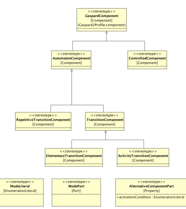
reactive systems. This package is summarized in the Figure 6.1.
6.2
Description
6.2.1 AutomatonComponent
An AutomatonComponent is a GaspardComponent which manipulates modes (in the meaning of a automaton state). From a previous mode, and possibly other inputs, it computes the new mode. Generalization
This generalizes GaspardComponent. Constraints
An AutomatonComponent has only one output port, through which signals about mode will go:
inv: self.ownedPort.required->size()=1 and self.ownedPort.required.stereotype->exists(name=’ModePort’)
6.2.2 RepetitiveTransitionComponent
A RepetitiveTransitionComponent is the way to express an automaton by following the Array-OL view. By repeating over time a TransitionComponent and using an inter-repetition dependence of +1 to report the current state of the automaton to the next instance, the execution of the automaton is indirectly described.
Generalization
Constraints
A RepetitiveTransitionComponent contains one and only one TransitionComponent, no other component. This is expressed by this OCL constraint:
inv: self.part->size()=1 and self.part.stereotype->exists(s| s.name=’ElementaryTransitionComponent’ or s.name=’ActivityTransitionComponent’)
6.2.3 TransitionComponent
The TransitionComponent is used to specify the transition function of an automaton. Generalization
This generalizes AutomatonComponent. Constraints
A TransitionComponent must have one and only one InterRepetition with a
repetitionSpaceDependence of [1] though which modes will flow. This is partially expressed by:
inv: self.connector->select(stereotype->exists(name=’InterRepetition’)->size()=1)
A TransitionComponent cannot be modeled alone, it has to be inside a
RepetitiveTransitionCompo-nent:
inv: self.owner.stereotype->exists(name=’RepetiveTransitionComponent’)
6.2.4 ElementaryTransitionComponent
This defines a transition function of an automaton which should be regarded as a black box from the Gaspard2 perspective (code is executed from the previous state and the result is the new state but nothing is none about the inner of the code).
Generalization
This generalizes TransitionComponent. Constraints
ElementaryTransitionComponent is an elementary component, it cannot contain any component, this
is expressed by this OCL constraint:
inv: self.part->select(stereotype->exists(name=’GaspardComponent’))->size()=0
6.2.5 ActivityTransitionComponent
This defines a transition function of an automaton which is specified by a UML activity diagram associated to this component.
Generalization
This generalizes TransitionComponent. Constraints
ActivityTransitionComponent is an elementary component, it cannot contain any component,
addition-ally it must be an Activity diagram. This is expressed by this OCL constraint:
6.2.6 ControlledComponent
This component is controlled: it is linked to an AutomatonComponent via a ModePort which will indicates in which mode it has to run. Depending on the mode, the ControlledComponent will run one and only one of the AlternativeComponentParts it is composed of. Internally, the ModePort is not linked to anything.
Generalization
ControlledComponent generalizes GaspardComponent.
Constraints
All the parts which composes this component must be AlternativeComponentPart. This is expressed by this OCL constraint:
inv:self.part->forAll(stereotype->exists(name=’AlternativeComponentPart’))
Each AlternativeComponentPart must have a different activationCondition, this prevent from two parts to be run at the same time. This is expressed by this OCL constraint:
inv: self.part->select(taggedValue.name=’activationCondition’ implies forAll(p1, p2 |p1.taggedValue.value<>p2.taggedValue.value))
A ControlledComponent must have one and only one ModePort . This is through this ModePort that signals about the current running mode will be passed. This is expressed by this OCL constraint:
inv: self.ownedPort.provided->select(stereotype->exists(name=’ModePort’)->size()=1)
All the AlternativeComponentParts must have the same interface, that is the same ports (same interface, same shape, and same direction) and each port must be linked to the same port of the
ControlledComponent . This is partially said by this OCL constraint:
inv: self.part->forAll(p1,p2| (p1.ownedPort.provided=p2.ownedPort.provided) and (p1.ownedPort.required=p2.ownedPort.required))
At runtime, only the parts which have their activationCondition set to the same value as the current ModePort value are activated.
inv:
self->includes(p:part|p.activationCondition.value=ownedPort.provided->select(stereotype->exists(name=’ModePort’)).value) and self->excludes(p:part|p.activationCondition.value<>ownedPort.provided->select(stereotype->exists(name=’ModePort’)).value)
6.2.7 AlternativeComponentPart
If a part (an instance of a component) has this stereotype, it will be selected or not depending on the current mode of the automaton linked to the containing ControlledComponent.
Extension
This extends Property. Attributes
• +activationCondition: EnumerationLiteral This Literal must be a ModeLiteral and it represent the mode into which the part will be executed.
6.2.8 ModePort
Extension
ModePort extends Port.
Constraints
It can only be of type ModeLiteral (ie: an automaton mode):
inv: self.feature->exists(f|f.oclIsTypeof(’ModeLiteral’))
6.2.9 ModeLiteral
A Literal in an Enumeration with the stereotype ModeLiteral defines a mode of an automaton. Extension
ModeLiteral extends EnumerationLiteral.
6.3
Semantic
So far the control semantic has been specified only when associated to the application package of the Gaspard2 profile.
The execution of the application mixed with the control is mostly straightforward for the control part: the TransitionComponents are executed as ElementaryComponents . A ControlledComponent is similar to a hierarchic GaspardComponent but instead of executing several tasks simultaneously, one task only is executed at a given time, depending on the value available on the ModePort.
One point which differs mainly from the rest of the application semantic is the information flow of the mode. The flow is asynchronous from the rest of the inputs and outputs. A task will never have to wait for a signal on a ModePort. It executes as if no ModePort was present, as soon as a new array is available on each of the ports. The value of the current mode is the last one effectively sent. Therefore, the granularity of a mode change is the array, once an instance of a ControlledComponent is executed, the mode will never change. This implies that an application will behave differently to a mode change depending on the platform execution speed, this is an inherent behaviour of reactive systems.
Chapter 7
Package Association
7.1
Overview
The previous chapters have presented the mechanisms used to model applications and hardware architectures using the Gaspard2 profile. The objective of the association is to provide tools that bind an application (describing the behavior of the SoC) to an architecture (describing the physical components available on the SoC). The following mechanisms are similar to the concept of Deployment in UML, but allow a finer specification and a wider flexibility. They mainly consist in mapping tasks to active components and mapping data to memories, while handling hierarchy and repetitions. A graphical summary of the concepts is available in Figure 7.1.
7.2
Description
7.2.1 AllocationAn Allocation is a dependency going from an ApplicationComponent and going to a HardwareComponent. This symbolises that all the ApplicationComponent executions (or instances) will be done on the
HardwareComponent.
Extension
Allocation extends Dependency. 7.2.2 DataAllocation
DataAllocation is used to specify onto which memory an array will be mapped. As arrays do not
appear in the Gaspard2 profile, the dependency starts from the ApplicationComponent and owns an attribute portName to indicate the array.
Generalization
This generalizes Allocation. Attributes
• +portName: String specifies the port which corresponds to the mapped array. Constraints
This can only connect an ApplicationComponent to a Memory. 7.2.3 TaskAllocation
TaskAllocation is used to specify on which Processor an ApplicationComponent will be mapped.
Generalization
This generalizes Allocation. Constraints
This can only connect an ApplicationComponent or a Reshape to a Processor. 7.2.4 CommunicationAllocation
CommunicationAllocation is used to specify how to synchronize two memories. It describes how to
copy an array available on a Memory to a different Memory when two tasks do not share the same
Memory for a array. This is only useful when a connector is linking two ApplicationComponents which
have mapped the array associated to this communication on different Memories. The copy of the array is then done following a Route which contains the Memories, the Processors used to read and write the arrays and the Communication paths through which it will be done. A CommunicationAllocation goes from the connector linking the two ApplicationComponents to a CollaborationUse.
Generalization
This generalizes Allocation. Constraints
This can only be applied from a connector linking two ApplicationComponents together to a
Communi-cation.
7.2.5 Route
A Route is used to specify through which HardwareComponents will flow a communication. Extension
This extends Collaboration. Attributes
• +route: property, the HardwareComponents through which the route is going, ordered from the first one, transmitting data, to the last one, receiving data.
Constraints
A collaboration must be defined in the same namespace as the HardwareComponents it refers to. 7.2.6 OrderDependency
This dependency allows to specify in which order should two tasks be executed when they are mapped on the same Processor but no data dependency permits to decide when to execute them. This dependency goes from the first TaskAllocation which will be executed to the second TaskAllocation.
Extension
OrderDependency extends Dependency.
Constraints
OrderDependency can only link an Allocation, this is expressed by this OCL rule:
inv: self.participant->size()=2 and self.participant.forAll(stereotype->exists(name=’Allocation’))
7.2.7 Distribution
Distributionbrings the concept of Reshapes (as described in the factorization package) to the association.
It is significant only when the target component (hardware architecture) is repeated. By specifying a distribution on an Allocation, complex associations between a regular repeated application and a regular repeated architecture can be described. The array of tasks (resp. data) is mapped (distributed) to the array of Processors (resp. Memories). The attributes have the same meaning has in a Reshape. Each instance of a task being a point of the source array and each instance of processor being a point in the target array.
If the source or the destination component do not have any multiplicity, it is regarded as a array of 1 element.
Extension
Distribution extends Dependency. Attributes
• +sourceTiler: InstanceSpecification This points to an instance of Tiler which defines the association from the array of ApplicationComponents (task, arrays. . . ) to the pattern.
• +targetTiler: InstanceSpecification This points to an instance of Tiler which defines the association from the pattern to the array of HardwareComponents (processors, memories. . . ). • +patternShape: String This shape defines the dimensions of the pattern.
• +repetitionSpace: String This shape defines the bounds of repetition for each dimension. Constraints
This can only be applied to an Allocation.
7.3
Semantic
Allocation represents the concept of associating an ApplicationComponent (either a task or an array) to a HardwareComponent (either a Processor or a Memory). Once associated, all the specified instances of the ApplicationComponent will be executed (or saved) on the HardwareComponent. If the component is hierarchic, all the sub-component are mapped on the same HardwareComponent. In the case an
ApplicationComponent is connect with Tilers (to ports of a containing component), the Tilers are
mapped on the same HardwareComponent than the ApplicationComponent.
If a multiple dependency is used, all the combinations of link between the ApplicationComponents and the HardwareComponents are expressed with the same stereotype and tagged values applied. 7.3.1 Illustrative example
As an example we will show how to use those mechanism to describe the usual “block” distribution pattern. The example is based on an application composed by 32×32 elementary tasks, and an architecture composed by 4 processors. The architecture pattern is made of only 1 processor, that is, 4 patterns. Only the distribution of task is shown in this example, but the usage of distribution of data is very similar.
7.3.2 Block distribution
A block distribution consists in identifying n blocks (n = number of processors) among a set of tasks (represented by an array). All the blocks have the same dimensions and are compact, in this example: 8×32. Following the rules presented in the factorization section, the pattern elements are set out according to the fitting matrix. A compact pattern is represented by an identity matrix: for each dimension, the next element is at the current position translated of 1. The fitting Matrix is therefore [1,0;0,1]. The bounds of the fitting are [8,32], the patternShape.
Identifying the origin of each block of task is fairly straightforward and consists in representing [c/n,0] (where c is the size of a line and n is the number of processors). Therefore the paving vector has to be defined to [8,0]. The bound of the paving being the amount of processors: [4], the repetitionSpace.
The hardwareArchitecture tiler has to express that each pattern will be associated to one processor. This is done by specifying a fitting matrix to null. That is, all the elements of the pattern
are set on the same point as the origin. The fitting matrix is therefore [0]. In order to associate each pattern to a different processor, the paving matrix has to be the identity: [1]. The result can be seen in the Figure 7.2.
Bibliography
[1] Abdelkader Amar, Pierre Boulet, and Philippe Dumont. Projection of the Array-OL specification language onto the Kahn process network computation model. Rapport de recherche RR-5515, INRIA, mars 2005. http://www.inria.fr/rrrt/rr-5515.html. 30
[2] Arnaud Cuccuru. Modélisation unifiée des aspects répétitifs dans la conception conjointe
logi-cielle/matérielle des systèmes sur puce à hautes performances. PhD thesis, Université des sciences
et technologies de Lille, Laboratoire d’informatique fondamentale de Lille, novembre 2005. 3, 5 [3] Object Management Group, Inc., editor. UML 2 Infrastructure (Final Adopted Specifcation).
http://www.omg.org/cgi-bin/doc?ptc/2003-09-15, septembre 2003. 3
[4] WEST Team LIFL, Lille, France. Graphical array specification for parallel and distributed computing (GASPARD-2). http://www.lifl.fr/west/gaspard/, 2005. 3
Unité de recherche INRIA Lorraine : LORIA, Technopôle de Nancy-Brabois - Campus scientifique 615, rue du Jardin Botanique - BP 101 - 54602 Villers-lès-Nancy Cedex (France)
Unité de recherche INRIA Rennes : IRISA, Campus universitaire de Beaulieu - 35042 Rennes Cedex (France) Unité de recherche INRIA Rhône-Alpes : 655, avenue de l’Europe - 38334 Montbonnot Saint-Ismier (France) Unité de recherche INRIA Rocquencourt : Domaine de Voluceau - Rocquencourt - BP 105 - 78153 Le Chesnay Cedex (France)
Unité de recherche INRIA Sophia Antipolis : 2004, route des Lucioles - BP 93 - 06902 Sophia Antipolis Cedex (France)
Éditeur
INRIA - Domaine de Voluceau - Rocquencourt, BP 105 - 78153 Le Chesnay Cedex (France) http://www.inria.fr