Computer Science and Artificial Intelligence Laboratory
Technical Report
m a s s a c h u s e t t s i n s t i t u t e o f t e c h n o l o g y, c a m b r i d g e , m a 0 213 9 u s a — w w w. c s a i l . m i t . e d u
MIT-CSAIL-TR-2012-012
May 22, 2012
A Case for Fine-Grain Adaptive Cache Coherence
George Kurian, Omer Khan, and Srinivas Devadas
A Case for Fine-Grain Adaptive Cache Coherence
George Kurian, Omer Khan and Srinivas Devadas
Abstract—As transistor density continues to grow geomet-rically, processor manufacturers are already able to place a hundred cores on a chip (e.g., Tilera TILE-Gx 100), with massive multicore chips on the horizon. Programmers now need to invest more effort in designing software capable of exploiting multicore parallelism. The shared memory paradigm provides a convenient layer of abstraction to the programmer, but will current memory architectures scale to hundreds of cores? This paper directly addresses the question of how to enable scalable memory systems for future multicores.
We develop a scalable, efficient shared memory architecture that enables seamless adaptation between private and logically shared caching at the fine granularity of cache lines. Our data-centric approach relies on in-hardware runtime profiling of the locality of each cache line and only allows private caching for data blocks with high spatio-temporal locality. This allows us to better exploit on-chip cache capacity and enable low-latency memory access in large-scale multicores.
I. INTRODUCTION
In large single-chip multicores, scalability is critically con-strained by memory access latency. A large, monolithic phys-ically shared on-chip cache does not scale beyond a small number of cores, and the only practical option is to physically distribute memory in pieces so that every core is near some portion of the cache. In theory this provides a large amount of aggregate cache capacity and fast private memory for each core. Unfortunately, it is difficult to manage distributed private memories effectively as they require architectural support for cache coherence and consistency. Popular directory-based pro-tocols are complex to implement and validate and scale poorly with increasing core counts. Although directories enable fast local caching to exploit data locality, they can also lead to inefficient utilization of on-chip cache capacity and increased protocol latencies. There are many proposals for scalable directory protocols (e.g., SPATL [1] and SCD [2]), but these are complex to implement and validate.
The other option is to organize on-chip memory as logically shared, leading to Non-Uniform Cache Access (NUCA) [3]. Although this configuration yields better on-chip memory uti-lization, exploiting spatio-temporal locality using low-latency private caching becomes more challenging. To address this problem, data placement schemes have been proposed (e.g., R-NUCA [4]); however, these data placement schemes typically assume private level-1 caches and still require directories.
In this paper we develop a scalable, efficient shared memory architecture that enables seamless adaptation between private and logically shared caching at the fine granularity of cache lines. Our data-centric approach relies on runtime profiling of the locality of each cache line and only allows private caching for data blocks with high spatio-temporal locality. This allows our protocol to (i) better exploit on-chip cache capacity by
limiting replication of data across private caches, (ii) enable low-latency private caching when most beneficial, (iii) enable efficient and scalable tracking of sharers, and (iv) lower energy consumption by better utilizing on-chip cache and network resources.
II. BACKGROUND ANDMOTIVATION
Previous proposals for last level cache (LLC) organizations in multicore processors have organized them as private, shared or a combination of both [5], [6], [4], [7] while all other cache levels have traditionally been organized as private to a core.
The benefits of having a private or shared LLC organization depend on the degree of sharing in an application as well as data access patterns. While private LLC organizations have a low hit latency, their off chip miss rate is high in applications that exhibit a high degree of sharing due to cache line replica-tion. Shared LLC organizations, on the other hand, have high hit latencies since each request has to complete a round-trip over the interconnection network. This hit latency increases as we add more cores since the diameter of most on-chip networks increases with the number of cores. However, their off-chip miss rates are low due to no cache line replication.
Private LLC organizations limit the cache capacity available to a thread to that of the private LLC slice. This has an adverse effect on multiprogrammed workloads that have uneven dis-tributions of working set sizes. This is because a private LLC organization cannot take advantage of the caches on adjacent cores to reduce the off-chip miss rate of a single workload. We note that some proposals such as cooperative caching have been put forward to address this issue [8]. Shared LLC organizations mitigate this issue since they have flexibility in storing the data of a thread in various locations throughout the LLC.
Both private and shared LLC organizations incur significant protocol latencies when a writer of a data block invalidates multiple readers; the impact being directly proportional to the degree of sharing of these data blocks. Previous research concerning last level cache (LLC) organizations proposed a hybrid organization that combined the benefits of private and shared organizations. Two such proposals are Reactive-NUCA [4] and Victim Replication [6].
Reactive-NUCA classifies data as private or shared using OS page tables at page granularity and manages LLC allocation according to the type of data. For a 16-core processor, R-NUCA places private data at the LLC slice of the requesting core, shared data at a single LLC slice whose location is determined by computing a hash function of the address, and replicates instructions at a single LLC slice for every cluster of 4 cores.
Invalida(ons by U(liza(on
0% 10% 20% 30% 40% 50% 60% 70% 80% 90% 100% Pe rc en ta ge In va lid a/ on s (%) 7 6 5 4 3 2 1 0 >= 7 >=8 7 6 5 4 3 2 1Fig. 1. Invalidations vs Locality.
Evic%ons by U%liza%on
0% 10% 20% 30% 40% 50% 60% 70% 80% 90% 100% Pe rc en ta ge E vi c-on s (%) >=7 6 5 4 3 2 1 0 >= 8 7 6 5 4 3 2 1
Fig. 2. Evictions vs Locality.
Victim replication starts out with a private L1 and shared L2 organization and uses the local L2 slice as a victim cache for data that is evicted from the L1 cache. By only replicating the L1 capacity victims, this scheme attempts to keep the low hit latency of private design and as much of the working set as possible on chip.
The above schemes suffer two major drawbacks: (1) They leave the private caches unmanaged. A request for data allo-cates a cache line in the private cache hierarchy even if the data has no spatial or temporal locality. This leads to cache pollution since such low locality cache lines can displace more frequently used data. (2) Management of the LLC is based on coarse-grain data classification heuristics and/or pays no attention to the locality of the cache lines. For example, victim replication places all L1 cache victims into the local L2 cache irrespective of whether they will be used in the future. R-NUCA has a fixed policy for managing shared data and does not allow less or more replication based on the usefulness of data. R-NUCA also does all management at the OS page granularity and is susceptible to false classifications.
In this paper we motivate the need for a locality-based coherence allocation scheme for cache lines. Figures 1 and 2 show the percentage of invalidated and evicted lines as a function of their locality. The locality of a cache line is the number of accesses that a core makes to the line after it is brought into its private cache hierarchy before being invalidated or evicted. To avoid the performance penalties of invalidations and evictions, we propose to only bring cache lines that have high spatio-temporal locality into the private
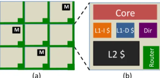
Core
L2 $
L1-‐I $ L1-‐D $ Dir Ro ut er (a) (b) M M MFig. 3. (a) The baseline system is a tiled multicore with an electrical mesh connecting the tiles. (b) Each tile consists of a processing core, L1-I cache, L1-D cache, L2 cache, directory, network router and connection to a memory controller (present only on some tiles).
caches and not replicate those with low locality. Adaptive Coherence is a protocol that accomplishes this by tracking vital statistics at the private caches and the directory to quantify the locality of data at the granularity of cache lines. This locality information is subsequently used to classify data as private or logically shared. In the next section, we describe the working of this protocol in detail, outline its advantages and compare it qualitatively with the protocols discussed in this section.
III. ADAPTIVECOHERENCE
A. Baseline System
The baseline system is a tiled multicore with an electrical 2-D mesh interconnection network as shown in Figure 3. Each tile consists of a compute core, private L1-I, L1-D and L2 caches, directory and a network router. Some tiles have a connection to a memory controller as well. The caches are kept coherent using a directory-based coherence protocol in which the directory is distributed across the entire processor, each tile containing a slice of it. The directory locations (/home-nodes) are cache-line interleaved across the entire processor.
We use a limited-directory [9] to store the list of sharers of a cache line since a full-map directory is not feasible for large scale multicores (∼1000 cores). In our limited-directory protocol, if the capacity of the sharer list is exceeded, a global
bit is set and the number of sharers is tracked1.
B. Adaptive Coherence Protocol Operation
Adaptive Coherence is a locality-based cache coherence protocol that ensures that a core gets a private copy of a cache line only if it has high spatio-temporal locality. In this paper, we add the Adaptive Coherence protocol on a Private-L1, Private-L2 cache organization and evaluate its benefits. However, the Adaptive Coherence protocol can also be added on top of other cache organizations like the Private-L1, Shared-L2 organization or the R-NUCA scheme to improve their performance and energy consumption.
We first define a few terms.
1On an exclusive request to such a cache line, an invalidation request
is broadcast to all the cores but acknowledgements are collected from just the actual list of sharers [10]. The electrical mesh in this system has native broadcast support and performs broadcasts by repeatedly duplicating messages on the output links of its network routers, forming a broadcast tree.
• Locality: Locality of a cache line is the number of times
it is used (read or written) by a core in its private cache before it gets invalidated or evicted.
• Private Caching Threshold (PCT): The cache line
locality for which a core is granted a private copy of a cache line.
• Private Sharer: A private sharer is a core whose cache
line locality is ≥ PCT.
• Remote Sharer: A core whose cache line locality is <
PCT.
• Private Cache-Line: A cache line is private to a core if
its locality for that core is ≥ PCT.
• Remote Cache-Line: A cache line is remote to a core if
its locality for that core is < PCT.
• Home-Node: The home-node for a cache line is the core
on which the directory entry for that cache line resides. Note that according to the above definitions, a cache line can be remote to one core and private to another. We will denote the Adaptive Coherence protocol added on top of a
Private-L1, Private-L2 organization as P-PPCT
adapt, where PCT is
a parameter to the protocol.
We first describe the operation of the protocol assuming that the directory is organized as full-map for each cache line. We
will later remove this assumption. The P-PPCT
adaptprotocol starts
out like a conventional directory-based protocol by marking all cache lines private with respect to all cores.
Consider read requests first. When a core makes a read request, the directory hands out a private read-only copy of the cache line if it is marked as a private sharer. The core then tracks the locality of the cache line in its private cache using a counter and increments it for every subsequent read. When the cache line is removed due to eviction (conflict or capacity miss) or invalidation (exclusive request by another core), the locality counter is communicated to the directory with the acknowledgement. The directory uses this information to determine if the core should be a marked as a private or remote sharer by comparing the counter with the PCT.
On the other hand, if the core is marked as a remote sharer, the directory replies with the requested word after reading it from its co-located L2 cache. If the cache line is not present in the L2 cache, it is brought in from external memory or from another L2 cache. This step is essential because even a small amount of locality suffices to eschew multiple expensive DRAM accesses. The directory also increments a sharer-specific locality counter. (Note that all sharer-sharer-specific locality counters are set to ‘0’ at start-up.) If the locality counter has reached PCT, the core is “promoted” and marked as a private sharer and a copy of the cache line is handed over to it.
Now consider write requests. When a core makes a write request, the directory performs the following actions if it is marked as a private sharer: (1) it invalidates all the private sharers of the cache line, (2) it sets the locality counters of all its remote sharers to ‘0’ and (3) it hands out a private read-write copy of the line to the requesting core. The core tracks the locality of the cache line in its private cache and sends this information to the directory when the line is removed. The
directory uses this information to classify the core as private or remote for future reference.
On the other hand, if the core is marked as a remote sharer, the directory performs the following actions: (1) it invalidates all the private sharers, (2) it sets the locality counters of
all sharers other than the requesting core to ‘0’2, and (3) it
increments the locality counter for the requesting core. If the locality counter has reached PCT, a read-write copy of the cache line is sent back to the requesting core. Otherwise, the word is stored in the home-node L2 cache.
Assume now that we have a limited directory, where we cannot keep track of all sharers, either private or remote. Before we address this problem, let us first classify private and remote sharers as active or inactive. A remote sharer is active if it has a non-zero locality counter and a private sharer is active if it contains a copy of the line in its private cache. An active private sharer can be indicated by storing a non-zero value in its locality counter in the directory at the time it is handed out a private cache line copy. The actual locality counter for an active private sharer is present in its private cache as described previously. An inactive private sharer is still marked as private in the directory for future reference. Only active private sharers need to be invalidated on a write request.
When a read request arrives at a limited-directory from a core, the directory looks up the sharer information and follows the following strategy:
• If the requesting core is already tracked, the directory
performs the functions outlined above, i.e., hands out a private copy or increments the locality counter.
• Else if the core is a new sharer that is not tracked,
the directory searches for an inactive remote sharer, an inactive private sharer and an active remote sharer with the least locality counter value, in that order. The first-found sharer is replaced with the new sharer. The directory treats the new sharer as a remote sharer and performs actions as described previously.
• Else, since the only sharers present are active private
sharers, the directory treats the new sharer as a private sharer as well and hands out a copy of the cache line. The directory entry switches to the broadcast mode and tracks the number of private sharers henceforth.
Write requests are very similar for full-map or limited directories. We summarize only the differences here. If the directory entry is in broadcast mode, an invalidation request is broadcasted and all active private sharers respond with an acknowledgement. If the requesting core is not already tracked (new sharer), the directory looks for an inactive remote sharer and replaces it, else it looks for an inactive private sharer and replaces it. An inactive sharer will always be found during a write request since all sharers are invalidated. In both cases, the new core is treated as a remote sharer and actions performed
2The locality counters of all the remote sharers other than that of the
requesting core need to be set to ‘0’ on a write because these sharers have been unable to show good locality for the line before getting invalidated.
accordingly.
The directory prioritizes tracking active private sharers. Remote sharers are tracked only in the absence of private sharers and are gradually phased out as more private sharers join. The number of hardware pointers in such a directory can be set below that in a conventional directory because the number of active private sharers decreases with increasing private caching threshold (PCT).
A new untracked core starts out as a remote sharer to ensure that it has good locality before being switched to private mode. The only exception to this rule is when only active private sharers exist in the directory. In this situation, the new core starts out as a private sharer because of the high likelihood that it also shows good locality for the cache line.
The cache tags and directory entries are similar to a limited directory protocol, except that additional counters for storing locality and private/remote mode information are required. C. Advantages
The Adaptive Coherence protocol has the following four advantages over conventional directory-based protocols.
1) By allocating cache lines only for private sharers, the protocol prevents the pollution of caches with low lo-cality data and makes better use of their capacity. Only a single-copy of the low-locality cache lines is maintained at the home node L2 cache to avoid off-chip memory accesses.
2) By prioritizing the tracking of private sharers over remote sharers, it reduces the number of hardware pointers needed per cache line in a limited directory-based protocol.
3) It reduces the amount of network traffic by removing in-validation, flush and eviction traffic for low locality data as well as by returning/storing only a word instead of an entire cache line when a request is made by a remote sharer. Reducing overall network traffic reduces network bandwidth requirements and more importantly, network energy consumption which is a growing concern since wires are not scaling at the same rate as transistors [11]. 4) Removing invalidation and flush messages and returning a word instead of a cache line also decreases the average memory latency, thereby improving processor performance.
D. Qualitative Differences with Existing Protocols
We now compare the P-PPCT
adapt protocol against a
conven-tional Private-L1, Private-L2 (P-P), a Private-L1, Shared-L2 (P-S), the R-NUCA protocol and the victim replication proto-col. The qualitative differences are summarized in Table I.
While all existing protocols bring a cache line into the L1 cache on every request irrespective of locality (indicated by
All in L1 Replication column), the P-PPCT
adapt protocol caches
only those lines with high spatio-temporal locality in its L1 and L2 caches (indicated by Selective in L1 and L2 Replication columns). The R-NUCA and victim replication protocols manage the L2 cache better but they use coarse-grain
Cache L1 L2 Tracked OS
Coherence Replication Replication Sharers Support
Protocol
P-P All All All No
P-S All One All No
R-NUCA All One1, All Yes
Cluster
Victim All One, All No
Replication Many2
P-PPCT
adapt Selective Selective Private No
TABLE I
QUALITATIVE DIFFERENCES BETWEEN CACHE COHERENCE PROTOCOLS.
1PLACED IN LOCAL/HOMEL2DEPENDING ON PRIVATE/SHARED DATA. 2ALL LINES PLACED IN HOMEL2AND VICTIM LINES REPLICATED IN
LOCALL2.
data classification and/or pay no attention to the locality of
cache lines. P-PPCT
adaptprotocol uses fine-grained cache line level
locality information for its operation. The R-NUCA protocol also needs OS page-table support for its operation whereas
the P-PPCT
adapt protocol works entirely at the hardware level.
The P-PPCT
adapt protocol prioritizes tracking private sharers and
hence, has lower directory size requirements than conventional directory-based protocols.
IV. EVALUATIONMETHODOLOGY
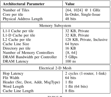
Architectural Parameter Value
Number of Tiles {64, 1024} @ 1 GHz
Core per tile In-Order, Single-Issue
Physical Address Length 48 bits
Memory Subsystem
L1-I Cache per tile 32 KB, Private
L1-D Cache per tile 32 KB, Private
L2 Cache per tile 128 KB, Private, Inclusive
Cache Line Size 64 bytes
Directory per tile 16 KB
Number of Memory Controllers {8, 64}
DRAM Bandwidth per Controller 5 GBps
DRAM Latency 100 ns
Electrical 2-D Mesh
Hop Latency 2 cycles (1-router, 1-link)
Flit Width 64 bits
Header (Src, Dest, Addr, MsgType) 1 flit
Word Length 1 flit (64 bits)
Cache Line Length 8 flits
TABLE II
ARCHITECTURAL PARAMETERS USED FOR EVALUATION.
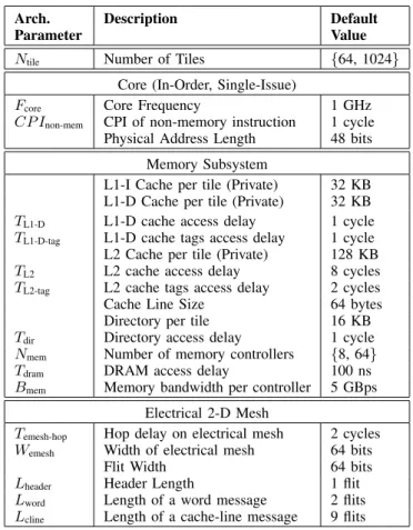
We evaluate both 64-tile and 1024-tile multicores. The important architectural parameters used for evaluation are shown in Table II. The directory is organized as full-map for the 64-tile processor, whereas for the 1024-tile processor, we use a limited directory with 6 hardware pointers in order to have the same storage as that for the tile processor. The 64-tile and 1024-64-tile processors use 8 and 64 memory controllers
respectively.
We develop an analytical model to evaluate the P-PPCT
adapt
protocol. The input statistics for the model are obtained by simulating fourteen SPLASH-2 [12] benchmarks, five PAR-SEC [13] benchmarks and a dynamic graph benchmark using the Graphite [14] multicore simulator. The dynamic graph benchmark models a social networking application that finds connected components in a graph [15]. Seven benchmarks (fft, barnes, radix, lu-contig, lu-noncontig, ocean-contig, ocean-noncontig) are evaluated at 1024-tiles. The remaining benchmarks are evaluated at 64-tiles due to limited scalability. We first run the benchmarks using the Private-L1, Private-L2 (P-P) organization in Graphite and collect a set of performance statistics. We then use the analytical model to turn these statistics into those for the
P-PPCT
adapt organization. For example, invalidation messages to
cache lines with low spatio-temporal locality are dropped and remote cache accesses to these lines are increased as the value of PCT is increased. A detailed description of this step and those to follow is presented in the Appendix.
Using four different analytical models, we quantitatively
evaluate the improvements obtained using the P-PPCT
adaptprotocol
along four dimensions, namely, directory size, network traffic, cache capacity and processor performance in order to explore the potential advantages mentioned in Section III-C. (i) The directory size model computes the average and maximum num-ber of hardware pointers needed in a limited directory protocol to service an exclusive request with minimal broadcasts. Since only private sharers need to be invalidated on an exclusive request, this value decreases with increasing PCT. (ii) The network traffic model computes the total number of messages injected into the network as a function of PCT. (iii) The cache capacity model computes the L1 and L2 cache capacity that could be saved by preventing private caching of lines with low spatio-temporal locality. (iv) The processor performance model computes CPI (Cycles per Instruction) as a function of PCT.
Our analytical models faithfully capture all delays in a shared memory system and an electrical mesh network, and uses M/D/1 queueing theory models to account for contention at the network router and memory controller [16].
V. RESULTS A. Directory Size
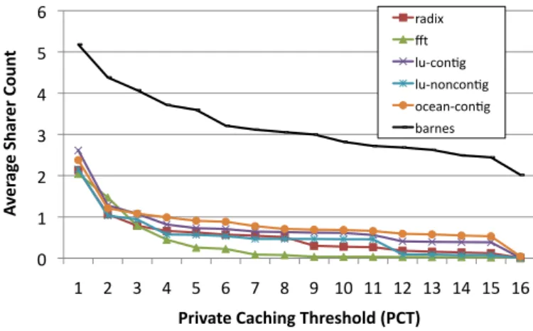
Figures 4 and 5 plot the average and maximum number of sharers that are invalidated on an exclusive request to the directory as a function of PCT. We only present the results for the 1024-tile processor since the scalability of directory size is not a major issue at 64 tiles. We observe that with increasing PCT, both the average and maximum sharer count drops. Although the exact number of hardware pointers needed in the limited directory can only be understood using detailed
simulations, these results indicate that the P-PPCT
adapt protocol
needs a fewer number of hardware pointers to match the performance of a conventional protocol. Since the directory size is proportional to the number of hardware pointers, the
0 1 2 3 4 5 6 1 2 3 4 5 6 7 8 9 10 11 12 13 14 15 16 Av er ag e Sh ar er C ou nt
Private Caching Threshold (PCT)
radix fft lu-‐con9g lu-‐noncon9g ocean-‐con9g barnes
Fig. 4. Average sharer count vs private-caching-threshold (PCT) for a 1024-tile architecture. 1 10 100 1000 10000 1 2 3 4 5 6 7 8 9 10 11 12 13 14 15 16 Ma xi m um S ha re r C ou nt (L og S ca le )
Private Caching Threshold (PCT)
radix fft lu-‐con9g lu-‐noncon9g ocean-‐con9g barnes
Fig. 5. Maximum sharer count (log scale) vs private-caching-threshold (PCT) for a 1024-tile architecture.
P-PPCT
adaptprotocol has the potential to make directory protocols
more scalable. B. Network Traffic
Figure 6 plots the network traffic of the P-PPCT
adapt protocol
as a function of private-caching-threshold (PCT). There are three factors working in different directions that affect network traffic.
(1) Remote requests and replies: The number of remote requests and replies for data increase with increasing PCT. Beyond a certain value of PCT, the communication overhead between the requester and directory is increased above that of a conventional protocol. This is due to the following reason.
In the P-PPCT
adaptprotocol, remote requests and replies together
occupy 3 flits in the network. Remote read requests are 1 flit wide and remote read replies are 2 flits wide since the replies contain the word that the core requested. On the other hand, remote write requests are 2 flits wide and remote write replies are 1 flit wide since the core supplies the word for the write. In conventional directory protocols, requests for a cache line are 1 flit wide while replies are 9 flits wide. This is because a cache line is 512 bits wide and occupies 8 flits on
0.8 0.85 0.9 0.95 1 1.05 1.1
water-‐nsquared water-‐spa4al radiosity dynamic-‐graph fluidanimate
CPI (N orma liz ed ) 1 3 5 7 9 11 13 15 0 0.2 0.4 0.6 0.8 1 1.2
lu-‐noncon4g dynamic-‐graph volrend radiosity fmm
N et w or k Tr affi c (Nor m aliz ed) 1 3 5 7 9 11 13 15
Fig. 6. Network traffic (normalized) vs PCT.
the network. Hence, four remote requests and replies exceed the communication in a conventional protocol between the requester and directory.
(2) Invalidation and flush messages: The number of invalidation and flush messages from the directory to service an exclusive request reduce with increasing PCT due to the decreasing number of private sharers (cf. Section V-A). Decreasing the number of invalidation and flush messages decreases the acknowledgement traffic as well. Acknowledge-ments may be more expensive since some of them contain data (e.g., response to a flush request).
(3) Evictions: The number of evictions decrease with in-creasing PCT since only data with high spatio-temporal local-ity is privately cached. Evictions of dirty data add significant network traffic since these cache lines need to be first routed to the directory to maintain consistent state and then to the memory controller to be written back to off-chip DRAM.
From Figure 6, we observe that the traffic decreases sud-denly at first, then saturates and finally, increases slowly as PCT reaches high values. The initial sudden decrease is because of the presence of cache lines with zero-locality that are brought into the cache and then evicted or invalidated before the core uses it a second time. The magnitude of the sudden decrease is proportional to the number of such zero-locality cache lines.
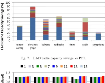
C. Cache Capacity
Figure 7 plots the percentage savings in the L1-D cache capacity as a function of PCT. Increasing PCT decreases the level of private caching, thereby increasing the savings in cache capacity. This graph is to be read in a cumulative manner, i.e., the cache capacity savings obtained by using a PCT of 7 include those obtained using a PCT of 6 and below. For example, the L1-D cache savings obtained in radix is 22% when PCT is 7 and 47% when PCT is 8. This implies that using a PCT of 8, radix can be run with 47% of the L1-D cache capacity of the baseline configuration (P-P) and still obtain the same number of cache misses for privately cached data. Of course, the data set that can be privately cached for
the P-P8
adapt configuration is smaller than that for the P-P
configuration.
The same plot for the L1-I cache is less promising because instructions have much higher locality than data. On average, a PCT of 8 can only save ∼8% of the cache capacity in the
0 10 20 30 40 50 60 70 80 90 100 lu non-‐
con2g dynamic graph volrend radiosity fmm radix swap2ons
L1 -‐D C ac he C ap ac ity S av in gs (%) 1 2 3 4 5 6 7 8 9 10 11 12 13 14 15 16
Fig. 7. L1-D cache capacity savings vs PCT.
0 0.2 0.4 0.6 0.8 1 1.2
water-‐nsquared water-‐spa5al radiosity dynamic-‐graph fluidanimate
CPI (N orma liz ed ) 1 3 5 7 9 11 13 15 0 0.2 0.4 0.6 0.8 1 1.2
lu-‐noncon5g dynamic-‐graph volrend radiosity fmm
N et w or k Tr affi c (Nor m aliz ed) 1 3 5 7 9 11 13 15
Fig. 8. CPI (normalized) vs PCT.
L1-I cache. For the L2 cache, however, the results are more promising since the low-locality cache lines that consume the capacity of L1-D cache affect the L2 as well. However, the savings in cache capacity are ∼2.5× smaller than that of the L1-D cache for similar values of PCT. The reasons for this are two-fold. Firstly, the savings in L2 cache capacity arise because the replication of low locality cache lines is prevented. However, these cache lines still need to be placed in a single L2 cache slice because off-chip accesses are expensive. On the other hand, low-locality cache lines are never placed in the L1 caches. Hence, the protocol yields greater savings in the L1-D cache capacity. Secondly, low-locality data resides almost as long in the L1-D cache as it does in the L2 cache.
Since the L1-D cache is only 1
4th the size of the L2 cache, the
cache pollution is felt to a greater extent in the L1-D cache. D. Processor Performance
Figure 8 plots the CPI as a function of PCT. The observed CPI is similar for low and medium values of PCT and slightly increases at high values. The only exception to this rule is the dynamic-graph benchmark. For this benchmark, initially the CPI decreases slightly due to the presence of a large number of privately cached lines that are evicted or invalidated before a second use.
The CPI does not decrease with increasing PCT because in this evaluation, we have measured the impact of the protocol on two important architectural components, the directory and the cache independent of CPI. In a full-system execution-driven simulation, managing the directory better would reduce the number of broadcasts for the same directory size and the cache capacity that is saved could be used to store more
useful data. These two positive attributes of the system would decrease the CPI as well.
In this paper, we do not attempt to provide a value for PCT. This needs to be derived through detailed simulations. Instead, we motivate the need for a protocol that considers the locality of a cache line as a first-order design parameter and evaluate its advantages.
VI. CONCLUSION
In this paper, we have proposed a scalable and efficient shared memory architecture that enables seamless adaptation between private and logically shared caching at the fine granularity of cache lines. Our data-centric approach relies on in-hardware runtime profiling of the locality of each cache line and only allows private caching for data blocks with high spatio-temporal locality. Using simulations and analytical models, we motivate the need for the proposed Adaptive Coherence protocol.
REFERENCES
[1] H. Zhao, A. Shriraman, S. Dwarkadas, and V. Srinivasan, “SPATL: Honey, I Shrunk the Coherence Directory,” in PACT, 2011.
[2] D. Sanchez and C. Kozyrakis, “SCD: A Scalable Coherence Directory with Flexible Sharer Set Encoding,” in HPCA, 2012.
[3] C. Kim, D. Burger, and S. W. Keckler, “An Adaptive, Non-Uniform Cache Structure for Wire-Delay Dominated On-Chip Caches,” in ASP-LOS, 2002.
[4] N. Hardavellas, M. Ferdman, B. Falsafi, and A. Ailamaki, “Reactive NUCA: Near-Optimal Block Placement and Replication in Distributed Caches,” in ISCA, 2009.
[5] P. Conway, N. Kalyanasundharam, G. Donley, K. Lepak, and B. Hughes, “Cache Hierarchy and Memory Subsystem of the AMD Opteron Pro-cessor,” IEEE Micro, vol. 30, no. 2, pp. 16–29, Mar. 2010.
[6] M. Zhang and K. Asanovi´c, “Victim Replication: Maximizing Capacity while Hiding Wire Delay in Tiled Chip Multiprocessors,” in ISCA, 2005. [7] C. Fensch and M. Cintra, “An OS-based Alternative to Full Hardware
Coherence on Tiled CMPs,” in HPCA, 2008.
[8] J. Chang and G. S. Sohi, “Cooperative Caching for Chip Multiproces-sors,” in ISCA, 2006.
[9] A. Agarwal, R. Simoni, J. L. Hennessy, and M. Horowitz, “An Evalu-ation of Directory Schemes for Cache Coherence,” in ISCA, 1988. [10] G. Kurian, J. Miller, J. Psota, J. Eastep, J. Liu, J. Michel, L. Kimerling,
and A. Agarwal, “ATAC: A 1000-Core Cache-Coherent Processor with On-Chip Optical Network,” in PACT, 2010.
[11] S. Borkar, “Panel on State-of-the-art Electronics,” NSF Workshop on Emerging Technologies for Interconnects http://weti.cs.ohiou.edu/, 2012. [12] S. C. Woo, M. Ohara, E. Torrie, J. P. Singh, and A. Gupta, “The SPLASH-2 Programs: Characterization and Methodological Consider-ations,” in ISCA, 1995.
[13] C. Bienia, S. Kumar, J. P. Singh, and K. Li, “The PARSEC Benchmark Suite: Characterization and Architectural Implications,” in PACT, 2008. [14] J. E. Miller, H. Kasture, G. Kurian, C. G. III, N. Beckmann, C. Celio, J. Eastep, and A. Agarwal, “Graphite: A Distributed Parallel Simulator for Multicores,” in HPCA, 2010.
[15] “DARPA UHPC Program BAA,” https://www.fbo.gov/spg/ODA/ DARPA/CMO/DARPA-BAA-10-37/listing.html, March 2010. [16] A. Agarwal, “Limits on Interconnection Network Performance,” IEEE
Transactions on Parallel and Distributed Systems, 1991. APPENDIX
We use an analytical model to evaluate the performance
impact of the P-PPCT
adaptcache organization. The input statistics
for the analytical model are obtained by simulating fourteen SPLASH-2 [12] benchmarks, five PARSEC [13] benchmarks and a dynamic graph benchmark [15] using the Graphite [14]
multicore simulator. We consider 64-tile and 1024-tile proces-sors. Each tile consists of a compute core, L1-I cache, L1-D cache, L2 cache, directory, network router and an optional connection to a memory controller. The detailed architectural parameters used for evaluation are shown in Table III. The first column in Table III (if specified) is the name used for the parameter in the analytical models that follow.
Arch. Description Default
Parameter Value
Ntile Number of Tiles {64, 1024}
Core (In-Order, Single-Issue)
Fcore Core Frequency 1 GHz
CP Inon-mem CPI of non-memory instruction 1 cycle
Physical Address Length 48 bits
Memory Subsystem
L1-I Cache per tile (Private) 32 KB
L1-D Cache per tile (Private) 32 KB
TL1-D L1-D cache access delay 1 cycle
TL1-D-tag L1-D cache tags access delay 1 cycle
L2 Cache per tile (Private) 128 KB
TL2 L2 cache access delay 8 cycles
TL2-tag L2 cache tags access delay 2 cycles
Cache Line Size 64 bytes
Directory per tile 16 KB
Tdir Directory access delay 1 cycle
Nmem Number of memory controllers {8, 64}
Tdram DRAM access delay 100 ns
Bmem Memory bandwidth per controller 5 GBps
Electrical 2-D Mesh
Temesh-hop Hop delay on electrical mesh 2 cycles
Wemesh Width of electrical mesh 64 bits
Flit Width 64 bits
Lheader Header Length 1 flit
Lword Length of a word message 2 flits
Lcline Length of a cache-line message 9 flits
TABLE III
DETAILED ARCHITECTURAL PARAMETERS
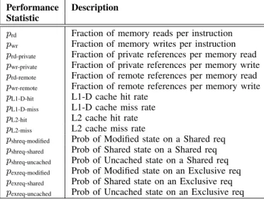
We first run the benchmarks using the P-P cache organiza-tion in Graphite [14] and collect a set of performance statistics (summarized in Table IV). We then use an analytical model (described in subsequent sections) to turn these statistics into
those for the P-PPCT
adapt organization. For example, invalidation
messages to cache lines with low spatio-temporal locality are dropped and remote cache accesses to these lines are increased as the value of PCT is increased. Sections A, B, C, D and E refer to Tables III and IV, so any parameters not explicitly described can be found in the tables.
We quantitatively evaluate the improvements obtained
us-ing the P-PPCT
adapt protocol along four axes, namely, processor
performance, network traffic, cache capacity and directory size. The processor performance model in Section B computes CPI as a function of PCT. This model faithfully captures all delays in a shared memory system and an electrical mesh network and uses M/D/1 queueing theory models to account for contention at the network router and memory controller.
Performance Description Statistic
prd Fraction of memory reads per instruction
pwr Fraction of memory writes per instruction
prd-private Fraction of private references per memory read
pwr-private Fraction of private references per memory write
prd-remote Fraction of remote references per memory read
pwr-remote Fraction of remote references per memory write
pL1-D-hit L1-D cache hit rate
pL1-D-miss L1-D cache miss rate
pL2-hit L2 cache hit rate
pL2-miss L2 cache miss rate
pshreq-modified Prob of Modified state on a Shared req
pshreq-shared Prob of Shared state on a Shared req
pshreq-uncached Prob of Uncached state on a Shared req
pexreq-modified Prob of Modified state on an Exclusive req
pexreq-shared Prob of Shared state on an Exclusive req
pexreq-uncached Prob of Uncached state on an Exclusive req
TABLE IV
PERFORMANCE STATISTICS OBTAINED BY SIMULATION
The network traffic model in Section C computes the total number of messages injected into the network as a function of PCT. The cache capacity model in Section D computes the L1 and L2 cache capacity that could be saved by preventing private caching of lines with low spatio-temporal locality. And finally, the directory size model in Section E computes the maximum and average number of hardware pointers needed in a limited-directory-based protocol to service an exclusive request with minimal broadcasts. It explains how this value decreases with increasing PCT.
A. Hybrid Protocol Statistics
Here, we describe how we turn the statistical data for the
P-P organization into those for the P-PPCT
adapt organization. The
value of PCT affects the number of private and remote sharers of a cache line. Increasing PCT decreases the number of private sharers and increases the number of remote sharers. This affects the memory latency as well as the communication patterns and traffic.
A high value of PCT leads to low traffic between the direc-tory and the private sharers of a cache line since invalidation and flush traffic is reduced. On one hand, it increases the number of requests to remote cache lines. Each such request is a round-trip that consists of two messages, with a combined length of 3 flits. On the other hand, fetching an entire cache line requires moving 10 flits over the network between the directory and requester. (1 flit for request, 9 flits (8+1) for reply). Hence, a locality of 4 or more implies that it is better to fetch the cache line on the first request as far as communication traffic between the requester and directory is concerned.
Converting event counters obtained from Graphite for the
P-P cache organization into that for the P-PPCT
adaptcache
organi-zation involves adding in new messages for remote read/write requests and subtracting out messages that are no longer needed due to the presence of the cache line at the home-node. For example, cache lines with locality < PCT are assumed
to always reside in the home-node L2 cache and not in the requester core; any invalidation or flush messages to them are removed. On the other hand, cache lines with locality ≥ PCT are handed out at the first request. Doing this at runtime requires the presence of a dynamic oracle that can predict the locality of a cache line when a core makes a request for it. On the other hand, the Adaptive Coherence protocol described in Section III uses the locality information in one turn to predict whether the sharer will be private or remote in the next. There might be a classification error associated with this method. We ignore this error in the evaluation and assume 100% accurate prediction.
B. Processor Performance Model
1) CPI: The performance of a processor is computed as a function of the CPI of each core, which is calculated using a simple in-order processor model. Because of the different actions taken in the cache coherence protocol, reads and writes are modeled separately. The basic equation for CPI is,
CPI = CPInon-mem+ prdtrd+ pwrtwr (1)
where prdand pwrare the fractions of memory reads and writes
per instruction and trdand twr are their latencies.
Now, since each cache line can be in either private or remote mode with respect to any given core, these two cases need to be modeled separately.
trd= prd-privatetrd-private+ prd-remotetrd-remote
twr= pwr-privatetwr-private+ pwr-remotetwr-remote
Memory Requests to Private Cache Lines: For a read request to a private cache line, the L1 cache is searched followed by the L2 cache. If a miss occurs in the L2, a request is sent to the directory to fetch a copy of the cache line.
trd-private= pL1-D-hit× TL1-D
+ pL1-D-miss× (TL1-D-tag+ TL2)
+ pL1-D-miss× pL2-miss× tshreq
where tshreqis the time taken to fetch a shared private copy of
the cache line.
The same basic equation is true for a write request as well. twr-private= pL1-D-hit× TL1-D
+ pL1-D-miss× (TL1-D-tag+ TL2)
+ pL1-D-miss× pL2-miss× texreq
where texreqis the time taken to fetch an exclusive private copy
of the cache line.
The directory handles a shared request for a private cache line copy depending on the state of the line. If the line is not present on-chip, it is fetched from off-chip memory by forwarding the request to the memory controller. If it is present on-chip (in either modified or shared state), it is fetched from a sharer. Once the cache line is brought to the directory, appropriate state changes are made and it is then forwarded
to the requesting core.
tshreq= temesh-header+ Tdir
+ (pshreq-modified+ pshreq-shared) × tsharer-fetch
+ pshreq-uncached× tmem-fetch
+ Tdir+ temesh-cline (2)
The directory handles an exclusive request for a private cache line copy in the same way. If the line is in modified state, it is fetched from its owner. If it is in shared state, it is fetched from a sharer and all sharers are invalidated. If it is not present on-chip, it is fetched from off-chip. Once the cache line is brought to the directory, it is forwarded to the requesting core.
texreq= temesh-word+ Tdir
+ pexreq-modified× tsharer-fetch
+ pexreq-shared× (tsharer-fetch+ Lheader-emesh× navg-sharers)
+ pexreq-uncached× tmem-fetch
+ Tdir+ temesh-cline (3)
where navg-sharers is the average number of sharers of a cache
line on an exclusive request to it.
Note that for an exclusive request, the word to be written is sent along with the request since it is the directory that determines whether a core is a private or remote sharer. In
equations (2) and (3), temesh-header, temesh-word and temesh-cline
denote the network latencies of a simple coherence message, a message containing a word that is read or written and a
message containing a cache line respectively. tsharer-fetch and
tmem-fetch denote the time taken to fetch a cache line from a
sharer on-chip and from off-chip memory respectively. The time to fetch a cache line from a sharer on-chip includes the network delay for sending a request, L2 cache access delay and the network delay for sending back the cache line.
tsharer-fetch= temesh-header+ TL2+ temesh-cline
The time to fetch a cache line from memory includes the network delay for sending a request to the memory controller, contention delay at the memory controller, DRAM access delay, off-chip serialization delay and the network delay for sending back a cache line.
tmem-fetch= temesh-header+ tdram-cline+ temesh-cline (4)
The term tdram-cline captures three of the above quantities.
Memory Requests to Remote Cache Lines: Remote read and write memory requests are handled by forwarding them over to the directory. The directory reads or writes the data in its associated L2 cache. If the line is not present on-chip, it is fetched from off-chip memory.
trd-remote = TL1-D-tag+ TL2-tag
+ temesh-header+ Tdir
+ pshreq-uncached× tmem-fetch
+ TL2+ temesh-word (5)
twr-remote= TL1-D-tag+ TL2-tag
+ temesh-word+ Tdir
+ pshreq-uncached× tmem-fetch
+ TL2+ temesh-header (6)
For remote write requests, the word is included within the request to the directory whereas for remote read requests, the word is returned back in the reply. Note that the L1-D and L2 tags need to be still accessed since it is at the directory where it is determined that the core making the read/write request is a remote sharer.
Electrical Mesh Latency: The electrical mesh latency of a
message of length ` flits is given by tflit+ (` − 1), where tflit
is the latency of a single flit through the network, assuming uniformly distributed senders and receivers and (` − 1) is the serialization delay. Hence,
temesh-header= tflit+ `header-emesh− 1
temesh-word= tflit+ `word-emesh− 1
temesh-cline= tflit+ `cline-emesh− 1 (7)
where `header-emesh, `word-emesh and `cline-emesh are the number
of flits in a header, word and cache-line network message respectively.
By the model given in [16],
tflit= dp2p(Temesh-hop+ Qemesh-router)
where dp2p is the mean number of hops between sender and
receiver and Qemesh-router is the contention delay at a router.
For an electrical mesh network on Ntile nodes, dp2p =
2√Ntile
3 .
DRAM Access Latency: The DRAM access latency con-sists of three components, namely, the off-chip contention
delay at the memory controller (Qmem), the fixed DRAM
access cost (Tdram) and the off-chip serialization delay which
is dependent on message size and DRAM bandwidth. tdram-cline= Qmem+ (Tdram+BLcline
mem)Fcore (8)
2) Queueing Delay: There are two queueing delays of
interest: the queueing delay off-chip (Qmem) and the queueing
delay in the on-chip network (Qemesh-router). In either case,
delay is modeled by an M/D/1 queueing model with infinite queues. In this model, queueing delay is given by
Q = λ
2µ(λ − µ) (9)
where λ is the arrival rate and µ is the service rate.
Off-Chip Queueing Delay: The off-chip queuing delay is slightly simpler, so that is derived first. To get the delay in terms of cycles, we must express the off-chip bandwidth in cache lines per cycle.
µmem= FBmem
where Lcline is the width of a cache line (in bytes).
The arrival rate is the off-chip memory miss rate per cycle per memory controller. Miss rates are given per instruction, so the arrival rate is inversely proportional to CPI. The per-core arrival rate is given by
λmem,core= βCPImem
where βmem is the off-chip memory traffic in cache lines per
instruction per tile.
It is assumed that addresses use separate off-chip control lines and do not contend with data traffic. Therefore queueing delay is dominated by the much larger data packets. This gives an overall off-chip arrival rate of
λmem=NcoreNλmem,core
mem (11)
Qmem is given by substituting equations (10) and (11) into
equation (9).
Electrical Mesh Queueing Delay: Qemesh-routeris the
queue-ing delay at each router. By the model in [16], Qemesh-router= 1 − ρ3ρ dp2pd − 2
p2p (12)
dp2p is the average distance between two tiles. ρ is the
utilization of the mesh, which is given by λemesh-router
µemesh-router. Now,
µemesh-router = 1 since the link width of the electrical mesh
network is 1 flit.
λemesh-router= β4 CPIemesh (13)
Where βemeshis the electrical mesh traffic in flits per
instruc-tion per tile. This is computed in Secinstruc-tion C.
3) Solving for CPI: A complication with this model is that the CPI as given by equation (1) is dependent on several queueing delays that themselves depend on the CPI. Finding a consistent solution algebraically seems hopeless due to the nonlinearity of the queueing models and the large number of parameters.
Numerical methods address this. Iteration to a fixed point is ineffective because of the extreme instability of the CPI. But an equally simple solution works since the right side of equation (1), when viewed as a function of CPI, is monotonically decreasing. Therefore one can use binary search to find the fixed point. We used this method to find solutions to within 0.001 accuracy.
4) Sources of Error: There are a few known sources of error in the model:
• Queueing delay at the directory itself is not modeled.
With high utilization, there could be multiple outstand-ing requests that force delay in the processoutstand-ing of later requests.
• Flow control in the networks is not modeled. We assume
infinite queues in our queueing model, but in reality under high loads the networks will engage in some form of congestion control that limits performance.
C. Network Traffic Model
The overall network traffic (β = βemesh) is computed in
a similar way to CPI by modeling read and write requests separately.
β = prdβrd+ pwrβwr
Contributions from memory requests to private and remote cache lines are modeled separately as well.
βrd= prd-privateβrd-private+ prd-remoteβrd-remote
βwr= pwr-privateβwr-private+ pwr-remoteβwr-remote
For memory requests to private cache lines, a request is sent off the tile only in the event of an L2 miss.
βrd-private= pL1-D-miss× pL2-miss× βshreq
βwr-private= pL1-D-miss× pL2-miss× βexreq
For shared requests to private cache lines, βshreq= βheader+ βcline
+ (pshreq-modified+ pshreq-shared) × βsharer-fetch
+ pshreq-uncached× βdram-fetch
+ pclean-eviction× βclean-eviction+ pdirty-eviction× βdirty-eviction
Similarly, for exclusive requests to private cache lines, βexreq= βheader+ βcline
+ pexreq-modified× βsharer-fetch
+ pexreq-shared× (βsharer-fetch+ βinvalidation)
+ pexreq-uncached× βdram-fetch
+ pclean-eviction× βclean-eviction+ pdirty-eviction× βdirty-eviction
An invalidation message includes both a request for invali-dation and an acknowledgement and is sent to all the sharers on an exclusive request.
βinvalidation = 2 × navg-sharers× Lheader
For remote memory requests, βrd-remote = βheader+ βword
+ βshreq-uncached× βdram-fetch
+ βdirty-eviction× βdirty-eviction
βwr-remote = βword+ βheader
+ βexreq-uncached× βdram-fetch
+ βdirty-eviction× βdirty-eviction
For fetching a cache line from the memory controller, βdram-fetch= βheader+ βcline
The above equation holds true for fetching cache line from
D. Cache Capacity Model
Savings in L1 and L2 cache capacity for the Adaptive Coherence protocol is obtained because private caching is enabled for only those lines whose locality ≥ PCT (PCT being the private-caching-threshold). To compute the savings in capacity, counters are added in the Graphite simulator to track the lifetime of each cache line. Whenever a cache line is removed due to invalidation or eviction, its lifetime is added to a global counter that tracks the total lifetime of low-locality cache lines. This global counter is then divided by the product of the cache size, the total number of tiles and the completion time of the benchmark to obtain the fractional savings in capacity.
Denote the lifetime of cache line c as Lifetime(c), the cache
size (expressed in terms of number of cache lines) as Scache,
the total number of tiles as Ntile and the completion time as
Tbench. Then
Saved-CapacityPCT=
X
c∈C
Lifetime(c) if Locality(c) < PCT Scache Ntile Tbench
(14) However, it has to be ensured that there is at least one copy of the cache line existing at any point of time and this is not
accounted for in the calculation of Saved-CapacityPCT. For
example, while invalidating a cache line, if all sharers have a locality of 1 and P CT is 2, the sharer with the largest lifetime should not be considered in the calculation. This minor change is difficult to express analytically but is easy to keep track of in simulation.
E. Directory Size Model
The identity of sharers needs to be tracked in a directory-based cache coherence protocol to invalidate them on an exclusive request to a cache line. In massive multicore systems, the status of all possible cores cannot be tracked. Hence, architects have opted for limited-directory based protocols where only the identity of a limited number of sharers is tracked. The efficiency of this scheme is inversely proportional to how frequently a cache line has more sharers than the number of hardware pointers.
The Adaptive Coherence protocol reduces the number of private copies of cache lines, and thereby reduces the number of sharers that need to be tracked for invalidation in the limited directory. This number of sharers decreases as the value of private-caching-threshold (PCT) is increased. We track the average and maximum number of sharers for a cache line as a function of PCT when an exclusive request is made to it.
The average number of sharers is calculated by tracking the total number of invalidations as well as the total number of sharers (s) that are invalidated and subtracting out those sharers that have low spatio-temporal locality.
navg-sharers=
X
s∈S
1 if Locality(s) ≥ PCT
Total Invalidations (15)
The maximum number of sharers is calculated by tracking the number of sharers whose Locality(s) ≥ PCT on every exclusive request and taking the maximum value across the entire simulation.