Publisher’s version / Version de l'éditeur:
Canadian Geotechnical Journal, 38, February 1, pp. 161-174, 2001-02-01
READ THESE TERMS AND CONDITIONS CAREFULLY BEFORE USING THIS WEBSITE. https://nrc-publications.canada.ca/eng/copyright
Vous avez des questions? Nous pouvons vous aider. Pour communiquer directement avec un auteur, consultez la première page de la revue dans laquelle son article a été publié afin de trouver ses coordonnées. Si vous n’arrivez pas à les repérer, communiquez avec nous à PublicationsArchive-ArchivesPublications@nrc-cnrc.gc.ca.
Questions? Contact the NRC Publications Archive team at
PublicationsArchive-ArchivesPublications@nrc-cnrc.gc.ca. If you wish to email the authors directly, please see the first page of the publication for their contact information.
NRC Publications Archive
Archives des publications du CNRC
This publication could be one of several versions: author’s original, accepted manuscript or the publisher’s version. / La version de cette publication peut être l’une des suivantes : la version prépublication de l’auteur, la version acceptée du manuscrit ou la version de l’éditeur.
For the publisher’s version, please access the DOI link below./ Pour consulter la version de l’éditeur, utilisez le lien DOI ci-dessous.
https://doi.org/10.1139/cgj-38-1-161
Access and use of this website and the material on it are subject to the Terms and Conditions set forth at
Thermal performance of trench backfills used for frost protection of
water service lines
Zhao, J. Q.; Rajani, B. B.; Daigle, L.
https://publications-cnrc.canada.ca/fra/droits
L’accès à ce site Web et l’utilisation de son contenu sont assujettis aux conditions présentées dans le site LISEZ CES CONDITIONS ATTENTIVEMENT AVANT D’UTILISER CE SITE WEB.
NRC Publications Record / Notice d'Archives des publications de CNRC:
https://nrc-publications.canada.ca/eng/view/object/?id=96b1d423-5365-4ea2-8500-3bee86619a3c https://publications-cnrc.canada.ca/fra/voir/objet/?id=96b1d423-5365-4ea2-8500-3bee86619a3cThermal performance of trench backfills used for
frost protection of water service lines
Jack Q. Zhao, Balvant B. Rajani, and Lyne Daigle
Abstract: This paper describes the thermal performance of different configurations of trenches using various trench
geometries and backfill and insulation materials. A limited number of laboratory tests were conducted to confirm the thermal properties of the backfills reported in the literature. The frost protection of water service is measured in terms of the number of days it takes for the frost front to reach the depth of water service lines under sustained subzero surface temperatures. The study specifically included typical granular materials used within the City of Ottawa (for-merly the Region of Ottawa–Carleton), but the findings can be equally applied to other urban areas in Canada where the surficial terrain is rocky. The thermal analyses of the trenches were conducted using the finite element method that appropriately represents phase changes when the temperature falls below the freezing point of water. The analyses indi-cate that the use of sandwich insulation is ineffective, and that latent heat of backfill and native soils has a great im-pact on the frost protection of water service lines. A list of possible trench depths with different backfills and their thermal performance is provided.
Key words: backfill, thermal performance, frost penetration, water service, finite element analysis.
Résumé : Cet article décrit la performance thermique de différentes configurations de tranchées obtenues en variant les
géométries et les matériaux de remblai et d’isolation. Un nombre limité d’essais de laboratoire a été réalisé pour confirmer les propriétés thermiques des remblais rapportées dans la littérature. La protection contre le gel des conduits d’eau est mesurée en fonction du nombre de jours requis pour que le front de gel atteigne la profondeur des lignes de service d’eau à des températures de surface se maintenant sous zéro. L’étude a inclu spécifiquement des matériaux granulaires typiquement utilisés dans la région de Ottawa-Carleton, mais les résultats peuvent être appliqués également à d’autres régions urbaines au Canada où le terrain est rocheux à la surface. Les analyses thermiques des tranchées ont été réalisées par la méthode d’éléments finis qui représente de façon appropriée les changements de phase lorsque la température tombe sous le point de congélation de l’eau. Les analyses indiquent que l’utilisation d’isolant en sandwich est inefficace et que la chaleur latente du remblai et des sols locaux a un impact important sur la protection contre le gel des lignes de service d’eau. On fournit une liste de profondeurs possibles de tranchées avec différents remblais, et on fournit leur performance thermique.
Mots clés : remblai, performance thermique, pénétration du gel, services d’eau, analyse par éléments finis.
[Traduit par la Rédaction] Notes 174
Introduction
Water to residential and industrial customers is delivered from 150 mm (6 in.) to 200 mm (8 in.) diameter water mains usually buried under adjacent streets or sidewalks via 12 mm (1/2 in.) to 19 mm (3/4 in.) diameter copper or polyethylene (PE) tubing commonly referred to as water service lines. These service lines are typically laid at depths of 1.5–2.4 m in most urban areas within Canada and cross under asphalt concrete roads, concrete or asphalt concrete driveways, and lawns. Frost can penetrate to these burial depths during long Canadian winters and if the water does not flow in these ser-vice lines for an extended period of time, then the serser-vice lines can freeze and burst, with a resulting loss of water and
possible property damage. A recent example is when some residents in various municipalities across Canada experi-enced repeated freezing of their water service pipes in cold winters (McDonald et al. 1997; Raymond et al. 1999). The absence of residents from their properties can exacerbate the situation. The period of time for water to freeze can be as short as 12 h due to the relatively small quantity of water in the line, combined with a frost front that is at or deeper than the depth of pipe burial. In some circumstances it is not eco-nomical to lay water services below frost depth levels where surficial rock is present. Of course, snow cover can greatly reduce the risk of deeper frost penetration but it is not prac-tical to rely on it to protect water service lines from freezing. Several options are possible to remedy the freezing of ex-isting water service lines. One of these options is to request that customers open their taps to drip (referred to as the “Let-run”), which maintains water flow in the service lines (Raymond et al. 1999). In fact, this option can be automated so that an induction valve opens (most often in the laundry tub) automatically whenever the ground temperature near the water service lines reaches a specified level, say, 2°C. The
Received September 14, 1999. Accepted July 19, 2000. Published on the NRC Research Press Web site on February 20, 2001.
J.Q. Zhao, B.B. Rajani, and L. Daigle. Institute for
Research in Construction, National Research Council Canada, Ottawa, ON K1A 0R6, Canada.
extra costs associated with water loss which are still cheaper than thawing the service line are often picked up by the wa-ter utility. A second option is to lower the burial depth be-low expected frost depths. This option is not economical for most existing water service lines but is an important consid-eration for new installations.
Sepehr and Goodrich (1994) conducted a study where the primary focus was on the frost protection of water mains in clay when these are laid using a backfill with relatively high thermal conductivity such as controlled low strength materi-als (CLSM), which are mixtures of low cement content, sand, aggregates, and sometimes excavated soils (Adaska 1994). Thermal analysis was also conducted on the use of lightweight aggregate. Lightweight aggregate is produced in a rotary kiln from clay or shale with grain sizes varying in the range of 5–25 mm; however, this material is not always widely available. The focus of this paper is on the thermal protection of water service lines where different backfill ma-terials are used and where the native material is rock (lime-stone). The presence of rock is a worst-case scenario because rock can have very high thermal conductivity and therefore can lead to the earlier arrival of the frost front at the water service line than would be the case if the native material is sand or clay.
An ideal trench backfill is that which meets the require-ments of the buried pipes and the pavement structure. The general requirements for the backfill are as follows: easy to place with minimal or no compaction, low or no differential frost heave, cost effective, low strength to permit excava-tions with hand shovels, provide frost protection for the pipe, provide adequate lateral support for flexible pipes, and minimal long-term surface settlement under repeated traffic loads to maintain the integrity of the reinstated trench. All of these requirements are difficult to meet with any existing backfill and therefore efforts are required to design trenches that meet these conflicting requirements.
This paper reports on a recent study carried out for the City of Ottawa which was aimed at revising their current standards for burial depth of water service lines and on the use of trench backfill materials in different trench configura-tions. This study was preceded by a project (Kuraoka and Rajani 1996) where field measurements of soil temperatures were validated (Fig. 1) using thermal analysis. One-dimensional finite element analysis was conducted for a 1.4 m wide trench where the native and backfill soils were primarily granular. The field validation provided the impetus for a thorough revision of the current design standards used for the protection of water service lines by the City of Ot-tawa. The objective of this study was to develop recommen-dations to mitigate freezing potential of service lines. The study focused on two specific items: (i) evaluation of mal properties of native and backfill materials, and (ii) ther-mal analysis to determine ideal trench configurations with and without the use of insulation materials such as extruded or expanded polystyrene with particular emphasis on trenches in rock.
In this paper, the depth of the trench refers to the cover depth of the water service line as opposed to the depth to the bottom of the trench.
Thermal properties of native backfills, engineered backfills, and insulation materials
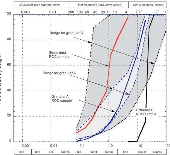
Water service lines are installed at the specific cover depth without the use of any particular bedding, which is not the case when water mains are laid. Water mains are usually laid underneath a street, and granular bedding and backfill are re-quired. For service lines, the native clay soil is commonly used as backfill material. Alternatively, materials referred to as granular C (Ontario Provincial Standard Specification 1993), granular A, and stone dust may be used for backfill-ing service lines in Ontario. Granular C and stone dust are Fig. 1. Comparison of measured and predicted temperatures at 2 m cover depth. Time 0 days = 24 Nov. 1994.
variations of granular materials used in Ottawa. These gran-ular materials consist of crushed rock or a mixture of crushed gravel, sand, and fines. The gradation characteristics of these materials are shown in Fig. 2; however, the thermal properties of these materials are not well established. There-fore, standard thermal conductivity measurements were conducted on samples in frozen and unfrozen conditions at different expected moisture levels.
The specified gradation of granular C materials covers a broad range of grain sizes and encompasses the range of granular A. Because the granular C specification is so wide, it was not surprising that one of the two samples of granular C material had a quite uniform grain size of 19 mm (3/4 in.) while the other had a gradation similar to that of granular A material. Thermal conductivity measurements were not con-ducted on the sample with uniform 19 mm particles because a proper test could not be conducted using the setup in our laboratory. The granular C sample with uniform 19 mm par-ticles resembles a soil reported by Farouki (1981). Thus, its saturated unfrozen and frozen thermal conductivities were inferred as 1.92 and 3 W/(m·K), respectively. These values were used for the thermal analyses reported in this paper. Specific heat values of these materials were obtained using the formulae given by Lunardini (1981).
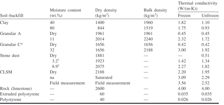
Thermal conductivities of clay, granular A, stone dust, and CLSM were measured in the laboratory using a desig-nated conductivity probe which was designed based on the transient line heat source method (Wechsler 1966; Goodrich
1977; Farouki 1981). The measured values are summarized in Table 1. CLSM is often used as a substitute for stone dust during winter repairs because of ease of placement and mini-mal long-term surface settlement of the trench. Thermini-mal properties of rock (limestone) are obtained from Johnston et al. (1981), and those for extruded and expanded polystyrene are from manufacturers’ catalogues. Extruded polystyrene and polyurethane insulation materials have thermal conduc-tivities of 0.035 and 0.026 W/(m·K), respectively.
Thermal analyses
Water service lines are usually 25–38 mm in diameter and, when stagnant, the heat from the water in these service lines can be practically neglected. Therefore, the water pipe has been excluded in the thermal analyses presented here. The thermal protection of water service lines is expressed in terms of days for the soil at the depth of the water service line to freeze after the date when the average air temperature falls below 0°C, shown as 13 November 1993 in Fig. 3. The aim of trench thermal design is to prevent the frost front from reaching the depth of the water service line. This is usually a period of approximately 130 days in Ottawa based on the weather records of Environment Canada. The simula-tions conducted herein used a period of 130 days of subzero air temperatures (Fig. 3).
Finite element discretization
All thermal analyses were conducted using the ABAQUS finite element software (Hibbitt, Karlsson & Sorensen 1996). ABAQUS is a powerful general purpose finite element pro-gram that can be used to solve a wide variety of field problems which includes the appropriate treatment of phase change of the water within the soil. It also permits the consideration of
trenches with different backfills, insulating materials, and boundary conditions. All finite element thermal analyses were conducted on a two-dimensional representation of the trench and the surrounding area. Furthermore, symmetry of the trench geometry permitted the solution of only half of the problem and thus led to a substantial reduction in com-putational effort. The finite element domain of corresponding Fig. 3. Air temperature – time history at ground surface.
discretization extended 15 m deep and 9 m across (half width) as shown in Fig. 4. Examples of the actual meshes used are shown with the results in Figs. 6 and 10.
The thermal and geotechnical engineering properties of the backfill and native materials are listed in Table 1. Differ-ent thermal properties were used for backfill and native soils depending on their frozen–unfrozen state. The latent-heat effect for the water in the soil was included in the analysis when appropriate. Latent heat is the amount of heat required to melt the ice (or released when water freezes) in a unit vol-ume of a mass without a change in temperature (Goodrich and Gold 1981).
Boundary conditions
The native rock at a depth of 15 m was assumed to be at a constant temperature of 12°C, which is representative of field measurements. The surface thermal boundary conditions were established using the average air temperatures for the most recent severe winter of 1993–1994 in Ottawa when a large number of frozen water service lines were experienced. As a first step, the ground temperatures of the trench and surrounding soil–rock were conditioned to the likely thermal ground regime by conducting thermal analyses with average monthly temperatures starting from 1 July to 31 October 1993. Then, the surface of the ground was subjected to a smoothed thermal loading curve that was estimated using the daily mean air temperatures for a period of 180 days starting on 1 November 1993 (Fig. 3). To verify if the use of the smoothed thermal loading curve is suitable, a 2.44 m trench (case 11-1) was analyzed using the actual daily mean air temperatures as shown in Fig. 3. The same trench was ana-lyzed again using the smoothed temperature curve (case 7-1). Analyses of these two cases yielded essentially the same results, i.e., in both cases the frost front reached the service line in 50 days. The temperature versus time plots (not shown) of the two cases were basically one on top of the other.
Therefore, the use of the smoothed thermal loading curve, which facilitated faster convergence during the executions of the transient finite element analysis models, is acceptable.
The ground surface temperatures were assumed to be the same as the air temperatures (n-factor = 1, Goodrich and Gold 1981; where the n-factor is defined as the ratio of the surface freezing index to the air freezing index) to represent locations where the service lines had to cross four-lane paved streets where snow was constantly cleared during win-ter (Raymond et al. 1999).
Once commenced, it was decided to conduct thermal anal-ysis of a trench in the rock formation in two stages. The first stage of the analysis considered trench depths of 0.92 and 2.44 m. The shallowest depth corresponds to the desired depth in rock to minimize rock excavations and corresponds to the requirements mandated by Ottawa. The cover depth of 2.44 m corresponds to the normal burial depth of water mains. The thermal analysis in the first stage clearly indi-cated that the water service line at 0.92 m had protection from frost for 33 days when the granular A backfill was sat-urated at a moisture content of 11%. A close look at the thermal analyses suggested that the high thermal conductiv-ity and lack of available latent heat in rock (limestone) play a dominant role in the heat transfer. Any changes to the de-sign of the trench would have to be de-significant to have an important impact on the thermal protection of water service lines. Furthermore, the analysis also demonstrated that a sur-face layer of 150 mm of granular A on top of 300 mm of granular C adjacent to the 2.44 m deep trench delays the ar-rival of the frost front at the water service line from 51 days to 109 days. These findings led to the second stage of the study where trench depths of 1.52, 1.83, and 2.13 m were analyzed. The 1.52 and 1.83 m depths were analyzed with a surface layer of 50 mm of lawn–sod, both with and without the use of extruded polystyrene insulation boards above or enclosing the service line.
Moisture content (wt.%) Dry density (kg/m3) Bulk density (kg/m3) Thermal conductivity (W/(m·K))
Soil–backfill Frozen Unfrozen
Clay 40 1400 1960 1.82 1.10 80 844 1519 1.75 0.93 Granular A Dry 1961 1961 0.45 0.45 11 2014 2240 2.32 1.72 Granular C* Dry 1656 1656 0.42 0.42 32 1656 2188 3.00 1.92
Stone dust Dry 1881 — — 0.51
3.2† 1923 — 1.42 1.34
8.9‡ 2075 — 2.27 1.82
CLSM Dry 2188 — 2.20 1.95
na Saturated — 3.09 2.29
Field measurement Field measurement 3.56 2.52
Rock (limestone) — 2600 — 4.00 4.00
Extruded polystyrene — 60 — 0.035 0.035
Polystyrene — 40 — 0.026 0.026
Note: na, not applicable.
*From Lunardini (1981).
†Dry of optimum moisture content. ‡At optimum moisture content.
The nonlinear analyses using temperature-dependent ther-mal properties were carried out with a minimum time step of 0.05 h and a maximum time step of 15 h. The finite element software can adjust time steps automatically to achieve faster convergence. The findings of these two stages of analyses are discussed in the following sections. The analysis of each trench configuration is designated a case number in Tables 2 and 3 with a suffix that refers to the stage of analysis, i.e., 1 and 2 representing the first and second stages of analyses, respectively.
Results and discussions of thermal analyses: first stage
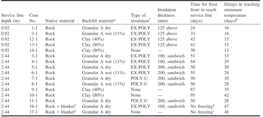
In this first stage of the analysis, two typical trench geom-etries were considered: a shallow trench (0.92 m) represent-ing a water service line crossrepresent-ing a ditch, and a deep trench (2.44 m) (Fig. 5). Backfill materials with two moisture con-tents, the use of different insulation thickness, type of insu-lation, and pavement subgrade were analyzed (cases 1-1 to 10-1). The results will be applicable to the most severe case of no surface granular layers. Surface granular layers, which is the normal case, were included in cases 13-1 and 14-1 with the 2.44 m deep trench.
The typical isotherm profile 25 days after commencement of below-zero surface temperatures for service line buried at a depth of 0.92 m is shown in Fig. 6 (case 1-1). Table 2 summarizes the number of days for the frost front to reach water service lines at depths of 0.92 and 2.44 m below the surface for various trench designs. The range of number of days for the frost to reach the water service line at the spe-cific depths in Table 2 is analyzed with respect to the effect of clay and granular A backfills with two moisture contents, the use of different insulation types and thicknesses, and the
presence of pavement subgrade adjacent to the trench. The analyses of the current design practice using native clay as backfill with no insulation around the water service lines (cases 9-1, 10-1, and 14-1) were also conducted for compar-ative purposes. The following key observations can be made regarding the results of the thermal analyses summarized in Table 2.
Cover depth 0.92 m (3 ft)
Cases 1-1 and 2-1 illustrate that saturated granular A re-tards the arrival of the frost front at the service line by 9 days, compared to the use of dry backfill, or as much as 1.4 times longer (Fig. 7). The use of clay backfill material in-stead of granular A can contribute considerably towards frost protection as indicated by comparing cases 12-1 and 13-1 with cases 1-1 and 2-1. However, the use of clay trench backfill is restricted to areas where settlement in reinstated trenches is not of major concern. The use of an insulation layer above the pipe (case 13-1) adds 4 days of thermal pro-tection to the pipe compared with the case without insulation (case 14-1) where clay backfill is used.
Cover depth 2.44 m (8 ft)
As expected, similar thermal behaviour with granular backfills (cases 3-1 and 4-1) is observed when the water ser-vice line is buried at a depth of 2.44 m (Fig. 8). The delay in the arrival of the frost front is 13 days, or approximately 1.2 times longer. A water service line in a clay-filled trench at a depth of 2.44 m (cases 9-1 and 10-1, moisture content 40% and 80%) and no insulation is protected from frost far longer than any other trench design analyzed, i.e., for 87 and 95 days, respectively (Table 2). This once again emphasizes Fig. 5. Trench geometry for 0.92 and 2.44 m cover depths.
that latent heat within the clay-filled trench does play a use-ful role in retarding frost penetration.
Thermal analyses in cases 3-1 and 5-1 suggest that a 200 mm (two 100 mm layers) layer of rigid extruded
poly-styrene insulation sandwiching the service line does not add more protection than a 100 mm (two 50 mm layers) layer for rock-filled trenches. This observation of “less protection with more insulation” was more evidenced in cases 4-1 and
Service line depth (m)
Case
No. Native material Backfill material*
Type of insulation†
Insulation thickness (mm)
Time for frost front to reach service line (days) Delays in reaching minimum temperature (days)¶
0.92 1-1 Rock Granular A dry EX-POLY 125 above 24 16
0.92 2-1 Rock Granular A wet (11%) EX-POLY 125 above 33 16
0.92 12-1 Rock Clay (40%) EX-POLY 125 above 42 15
0.92 13-1 Rock Clay (80%) EX-POLY 125 above 43 15
0.92 14-1 Rock Clay (80%) None — 39 13
2.44 3-1 Rock Granular A dry EX-POLY 100, sandwich 51 33
2.44 4-1 Rock Granular A wet (11%) EX-POLY 100, sandwich 64 29
2.44 5-1 Rock Granular A dry EX-POLY 200, sandwich 50 30
2.44 6-1 Rock Granular A wet (11%) EX-POLY 200, sandwich 55 28
2.44 7-1 Rock Granular A dry POLY-U 200, sandwich 50 30
2.44 8-1 Rock Granular A wet (11%) POLY-U 200, sandwich 56 28
2.44 9-1 Rock Clay (40%) None — 87 35
2.44 10-1 Rock Clay (80%) None — 95 42
2.44 11-1 Rock Granular A dry POLY-U 200, sandwich 50 28
2.44 16-1 Rock + blanket‡ Granular A dry EX-POLY 100, sandwich No freezing§ 47
2.44 17-1 Rock + blanket‡ Granular A dry None — No freezing2 46
*Moisture content is given in parentheses.
†EX-POLY, extruded polystyrene rigid insulation; POLY-U, polyurethane insulation.
‡Blanket consists of 150 mm of granular A (11% moisture content) underlain by 300 mm of granular C (32% moisture content). §Frost front did not reach water service line; maximum frost penetration was 2.41 m.
2
Frost front did not reach water service line; maximum frost penetration was 2.25 m.
¶Lag time between minimum surface temperature and minimum soil temperature at the pipe centreline.
Table 2. First stage analysis: water service line depths at 0.92 and 2.44 m.
6-1 where wet granular A backfills were used. This seem-ingly counterintuitive result indicates that the sandwiching method not only impedes the frost penetration downward to the pipe but also impedes the flow of heat up from below. This observation is investigated further in the second stage of the analyses. Comparison between the dry cases (cases 3-1, 5-3-1, and 7-1) and wet cases (cases 4-3-1, 6-3-1, and 8-1) shows that the latent heat effect adds 5–13 days of thermal protection.
Comparisons of the thermal analyses of cases 5-1 and 7-1 (dry granular A) and cases 6-1 and 8-1 indicate that rigid insulation (extruded polystyrene) and polyurethane insula-tion provide equal thermal protecinsula-tion to the water service line buried at a depth of 2.44 m. This result is not totally un-expected because the relative difference in thermal conduc-tivities of the polystyrene and polyurethane insulation materials is not as significant as that of the limestone rock or granular A.
All the trench designs discussed previously (cases 1-1 to 14-1) considered that the material adjacent to the trench is entirely native rock. However, a situation where the surficial materials consisting of subgrade (Fig. 4) such as granular A and C is more likely to exist under paved streets. Thermal analyses (cases 16-1 and 17-1) were conducted to reflect this situation, and it was found that the water service line was protected from freezing for the entire winter season for both
cases. Trenches with nonfrozen service lines are discussed later in the paper.
The effect of latent heat on frost penetration is demon-strated with the paired dry and wet analyses. Clay backfills with 80% moisture content show better protection than those with 40% moisture content. The results of all cases in the first stage show that time to the lowest temperature at the pipe location lags behind that of the minimum surface tem-perature (Table 2; Fig. 13). As expected, the deeper the ser-vice line, the longer the delay to reach the minimum temperature. Furthermore, when the frost front ceases to penetrate depends on the material properties of the surround-ing soils and the pipe burial depth.
Results and discussions of thermal analyses: second stage
Based on the results of the first stage analyses, it was de-cided not to vary the moisture content of the materials used in the second stage analyses. Moisture contents of 40 and 11% were used with clay and granular A materials, respec-tively. In situ moisture contents of these two materials at these levels can be expected.
Typical trench configurations analyzed for shallow and deep trenches with and without insulation are shown in Fig. 9. In the first stage of analysis it was found that a sur-face layer of granular material above the native rock and Fig. 7. Influence of different insulation materials and saturated clay on temperatures of water service line at 0.92 m (cases 1-1, 2-1,
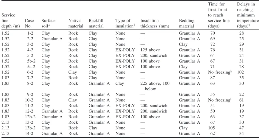
trench can significantly delay the arrival of the frost front at the depth of water service lines. Therefore, all trench config-urations in the second stage of analysis included a surface layer of clay, which is anticipated to have similar thermal properties to that of a lawn. The typical isotherm profile 48 days after commencement of below-zero surface tempera-tures for service line buried at a depth of 1.52 m is shown in Fig. 10 (case 4-2). Table 3 summarizes the number of days for the frost front to reach water services lines at depths of 1.52, 1.83, and 2.13 m for various trench designs. The range of days for the frost front to reach the water service line at the specific depths in Table 3 is analyzed with respect to the effect of different insulation types and thicknesses and a sur-face layer of lawn or sod.
Cover depth 1.52 m (5 ft)
The temperature histories with the cover depth of 1.52 m (cases 1-2 to 6-2) are shown in Fig. 11. The time for the ar-rival of the frost front at the service line varied from 64 days for case 5-2 to 76 days for case 4-2 for all rock trenches. The results indicate that 1.52 m rock trenches do not have enough thermal protection, even when insulation is used. Case 6-2 represents a clay trench with clay backfill, and the results show that the frost front did not reach the depth of the service line. In this case the temperature at the pipe depth did
not drop below the freezing point primarily because of the release of latent heat as the soil froze.
Case 5-2 represents a case where the service line is sandwiched between two 100 mm thick extruded polysty-rene insulation boards, whereas case 5b-2 represents a case where one 100 mm thick extruded polystyrene insulation board is placed directly above the service line. Case 5c-2 represents a case similar to that of case 3-2 except that one 100 mm thick extruded polystyrene insulation board was in-cluded above the service line. As shown in Table 3, the tem-perature at the pipe location for the 200 mm sandwich insulation case (case 5-2) reached the freezing point at 64 days, 3 days sooner than the case with only 100 mm of insu-lation at the top (case 5b-2). This analysis confirms that the bottom insulation impedes heat transfer from below. Com-parison of cases 3-2 and 5c-2 shows that addition of 100 mm of insulation directly above the service line in a clay-filled rock trench provides very little added thermal protection value. Thermal protection by adding one layer of 100 mm insulation was offset when the bedding was granular A ma-terial (case 5b-2) instead of clay (case 3-2). Latent heat in clay plays a more profound role than 100 mm of insulation in conjunction with 200 mm of granular A bedding.
Case 4-2 represents a case where the placement of a 125 mm thick insulation board is placed 120 mm above the Fig. 8. Influence of different insulation materials and saturated clay on temperatures of water service line at 2.44 m (cases 3-1, 5-1,
Fig. 9. Trench geometry for 1.52 and 1.83 m cover depths. Service line depth (m) Case No. Surface soil* Native material Backfill material Type of insulation† Insulation thickness (mm) Bedding material Time for frost front to reach service line (days) Delays in reaching minimum temperature (days)‡
1.52 1-2 Clay Rock Clay None — Granular A 70 28
1.52 2-2 Granular A Rock Clay None — Granular A 69 25
1.52 3-2 Clay Rock Clay None — Clay 72 29
1.52 4-2 Clay Rock Clay EX-POLY 125 above Granular A 76 31
1.52 5-2 Clay Rock Clay EX-POLY 200, sandwich Granular A 64 24
1.52 5b-2 Clay Rock Clay EX-POLY 100 above Granular A 67 31
1.52 5c-2 Clay Rock Clay EX-POLY 100 above Clay 71 28
1.52 6-2 Clay Clay Clay None — Granular A No freezing§ 102
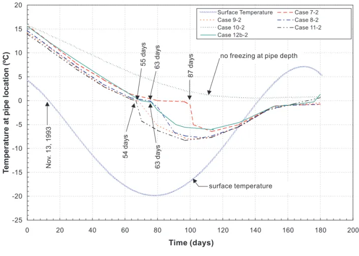
1.83 7-2 Clay Rock Clay None — Granular A 87 35
1.83 8-2 Clay Rock Granular A Clay 225 above, 100
below
Granular A 63 30
1.83 9-2 Clay Rock Granular A None — Granular A 55 22
1.83 10-2 Clay Clay Granular A None — Granular A No freezing2 61
1.83 11-2 Clay Rock Granular A EX-POLY 200, sandwich Granular A 54 19
1.83 12-2 Granular A Rock Granular A EX-POLY 200, sandwich Granular A 50 19
1.83 12b-2 Granular A Rock Granular A EX-POLY 100 above Granular A 63 37
2.13 13-2 Clay Rock Granular A None — Granular A 67 30
2.13 13b-2 Clay Rock Clay None — Clay 105 47
2.13 14-2 Granular A Rock Granular A None — Granular A 62 34
*Moisture content of clay = 40%; moisture content of granular A = 11%.
†EX-POLY, extruded polystyrene rigid insulation.
‡Lag time between minimum surface temperature and minimum soil temperature at the pipe centreline. §Frost front did not reach water service line; maximum frost penetration was 1.41 m.
2
Frost front did not reach water service line; maximum frost penetration was 1.70 m.
service line. In this case, the frost front took 9 days more to reach the pipe location than in case 5b-2 where the insulation is placed directly over the pipe. This result is in agreement with the recommendations by Sepehr and Goodrich (1994) that insulation should be placed as high as possible above the pipe.
Cover depth 1.83 m (6 ft)
The temperature histories at the cover depth of 1.83 m (cases 7-2 to 12-2) are shown in Fig. 12. The frost front reaches the service line after 87 days when the backfill is clay (case 7-2). Case 8-2 represents a special situation simu-lating a possible practice where a 325 mm layer of clay is used, sandwiching the service line, and the remaining trench is backfilled with granular A. The 325 mm clay layer is meant to protect the pipe from potential mechanical damage by fragmented rock if placed directly on the water service line. The time for the frost front to reach the water service line for case 8-2 is 63 days, approximately 8 days longer than in case 9-2 where only granular A backfill is used.
The placement of two 100 mm extruded polystyrene insu-lation boards sandwiching the water service line results in calculated frost front arrival times of 54 and 50 days when the surface layer is clay (case 11-2) and granular A (case 12-2), respectively. The frost front arrival time at the pipe loca-tion with insulaloca-tion (case 11-2) is 10 days less than that when insulation is not used (case 9-2). These analyses show that two 100 mm extruded polystyrene insulation boards did not add more thermal protection than granular A material. When the 100 mm insulation below the pipe was removed (case 12b-2), the top 100 mm of insulation does add more thermal protection than the case without insulation (case 9-2).
Cover depth 2.13 m (7 ft)
Cases 13-2 and 14-2 represent 2.13 m deep trenches in native rock with granular A backfill. No insulation materials were used. The difference between these two cases was the type of surface layer material, i.e., clay with 40% moisture content in case 13-2 and granular A with 11% moisture con-tent in case 14-2. The frost front reached the depth of the service line at 67 and 62 days with clay and granular surface material, respectively. The 5 day delay in the arrival time of the frost front is probably not practically significant, since a variation in surface layer depth or thermal properties can easily induce a similar change.
Water service lines will likely freeze towards the end of a long cold winter, i.e., after 105 days, when they are installed at 2.13 m below driveways in rocky areas and backfilled with clay (case 13b-2).
Trenches with nonfrozen service lines
Cases 16-1, 17-1, 6-2, and 10-2 are the trenches where the frost front did not reach the service line. Case 6-2 was a 1.52 m deep clay trench backfilled with clay, and case 10-2 was a 1.83 m clay trench backfilled with granular A mate-rial. These two cases show that to prevent the service pipe from freezing, an increase of 0.31 m in depth is required when the backfill material is changed from clay to granular A material.
Both cases 16-1 and 17-1 represent a 2.44 m rock trench backfilled with granular A material, except that case 16-1 also had a layer of polystyrene insulation. Therefore, the use of insulation is not necessary in this case. Since clay has a better thermal performance than dry granular A, one can conclude that under the same conditions but with clay Fig. 10. Partial plot of isotherms at 48 days after commencement of below-zero surface temperatures (case 4-2).
backfills the service line will not freeze either. This result confirms that the minimum design cover of 2.4 m for Ot-tawa is appropriate (Baker 1997), regardless of native and backfill material types.
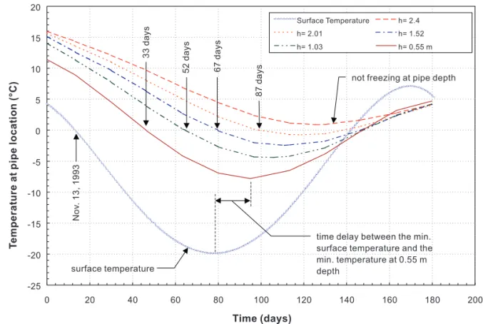
The temperature histories at five different depths along the centreline of the 2.44 m trench represented by case 17-1 are plotted in Fig. 13. The frost front reached depths of 0.55 m at 33 days, 1.03 m at 52 days, 1.52 m at 67 days, and 2.01 m at 87 days. The maximum depth reached was 2.23 m. There-fore, one can conclude that a service line buried deeper than 2.23 m, regardless of backfill material types, will not freeze. Summary and conclusions
The first stage of the analysis demonstrated that the ther-mal and geotechnical properties of backfill materials have an enormous influence on how fast the frost front pro-gresses through the backfill and native materials. The anal-ysis also verified that the use of a smoothed approximated temperature curve as thermal loading on the ground surface was appropriate. Thus, an analysis using this approach can be used in determining if a hazard exists for the water ser-vice to freeze. Backfill materials with high thermal
conduc-tivities and low moisture contents promote deeper frost penetration. Instances of this behaviour have been demon-strated with the use of controlled low strength material for backfills by Zhan et al. (1995), Rajani et al. (1995), and Baker (1997). It is prudent to consider both mechanical and thermal performance when selecting backfill materials for regions subjected to severe cold temperatures. A surface layer consisting of material with low thermal conductivity and (or) high moisture content significantly delays the pen-etration of the frost front. Use of granular C materials as trench backfill should be avoided, since its specification is so wide and it is possible to use a material that will not ad-equately reduce frost penetration.
The second stage of the analysis showed that the use of sandwich insulation in trenches is not effective due to the impedance of heat transfer from the soils below. Therefore, this practice should be discontinued. On the other hand, in-sulation placed on top of the water service line provides better thermal protection than the case without insulation. Clay backfill materials with a moisture content of 40% pro-vide more thermal protection than granular materials with a moisture content of 11%. Adding a layer of insulation in clay-backfilled trench does not add more thermal protection Fig. 11. Influence of different insulation materials and saturated clay on temperatures of water service line at 1.52 m cover depth
for the service line. Rather, latent heat in clay plays an im-portant role in delaying the arrival of the frost front at the depth of the water service line.
Based on the results presented, trenches of different depths with different backfills and their thermal performance are summarized in Table 4.
The study specifically included typical granular materials used within Ottawa, but the findings can be applied to other urban areas in Canada where the surficial terrain is rocky. The thermal analyses offer insight into the desirable combi-nations of material properties and trench geometries to in-crease frost protection for water service lines.
Fig. 12. Influence of different insulation materials and saturated clay on temperatures of water service line at 1.83 m cover depth
(cases 7-2 to 11-2 and 12b-2).
Characteristics Thermal performance
Shallow rock trenches of 0.92 m, granular backfill, 125 mm insulation above pipe Freezing in about 1 month Shallow rock trenches of 0.92 m, clay backfill, 125 mm insulation above pipe Freezing in about 1.5 months Rock trenches of 1.52 m, clay or granular backfill, no insulation Freezing between 1 and 2.5 months Rock trenches of 1.83 m, granular backfill, no insulation Freezing in about 1.8 months Rock trenches of 1.83 m, granular backfill, 100 mm insulation above pipe Freezing in about 2.1 months
Rock trenches of 1.83 m, clay backfill, no insulation Freezing in about 2.9 months
Rock trenches of 2.13 m, granular backfill, no insulation Freezing in about 2.1 months
Rock trenches of 2.13 m, clay backfill, no insulation Freezing in about 3.5 months
Clay trenches of 1.52 m and deeper, clay backfill, no insulation No freezing Clay trenches of 1.83 m and deeper, granular or clay backfill, no insulation No freezing Rock trenches of 2.23 m and deeper, granular or clay backfill, 450 mm granular surface
layer, no insulation
No freezing
Acknowledgements
The authors extend their appreciation to the staff at the Environment and Transportation Department of the City of Ottawa for their collaboration during the course of this study. The authors are grateful to Mr. Richard Desnoyers of the National Research Council of Canada for his review of and comments on this paper.
References
Adaska, W.S. (Editor). 1994. Controlled low-strength materials. American Concrete Institute, Publication SP-150.
Baker, T.H.W. 1997. Frost penetration in flowable fill used in pipe-line trench backfill. In The design and application of controlled low-strength materials (flowable fill). Edited by A.K. Howard and J.K. Hitch. American Society for Testing and Materials, Special Technical Publication STP 1331, pp. 275–282. Farouki, O.T. 1981. Thermal properties of soils. U.S. Army Corps
of Engineers, Cold Regions Research and Engineering Labora-tory, Hanover, N.H., Monograph 81-1.
Goodrich, L.E. 1977. Transient probe apparatus for soil thermal conductivity measurement. In Proceedings of the Symposium on Permafrost Field Methods, 3–4 Oct. 1977, Saskatoon, Sask., pp. 44–55.
Goodrich, L.E., and Gold, L.W. 1981. Ground thermal analysis. In Permafrost engineering design and construction. Edited by G.H. Johnston. John Wiley & Sons, New York, pp. 149–172. Hibbitt, Karlsson & Sorensen. 1996. ABAQUS. Hibbitt, Karlsson
& Sorensen, Pawtucket, R.I.
Johnston, G.H., Ladanyi, B., Morgenstern, N.R., and Penner, E. 1981. Engineering characteristics of frozen and thawing soils. In Permafrost engineering design and construction. Edited by G.H. Johnston. John Wiley & Sons, New York, pp. 73–147. Kuraoka, S., and Rajani, B. 1996. Insulation of water service lines:
heat transfer analysis of trench backfill with HDPE chips. Client
Report A-7014.2, Institute for Research in Construction, Na-tional Research Council of Canada, Ottawa.
Lunardini, V.J. 1981. Heat transfer in cold climates. Van Nostrand Reinhold Co., New York.
McDonald, S., Daigle, L., and Félio, G. 1997. Water distribution and sewage collection in Canada — assessing the condition of municipal infrastructure, results from questionnaires to Cana-dian municipalities. Client Report A-7016.1, Institute for Re-search in Construction, National ReRe-search Council of Canada, Ottawa.
Ontario Provincial Standard Specification. 1993. Material specifi-cation for aggregates — granular A, B, M and select subgrade material (OPSS 1010). In 1993 Ontario Provincial Standard Specifica-tion. Ontario Provincial Standard Specification (OPSS), Toronto. Rajani, B., Goodrich, L., and Cooke, B. 1995. Thermal
perfor-mance of trench backfills and mechanical perforperfor-mance of buried PVC water mains. Client Report A-7005.3, Institute for Research in Construction, National Research Council of Canada, Ottawa. Raymond, D., Zhao, J.Q., Scothorn, P., Rajani, B.B., and Daigle, L.
1999. A practical measure to prevent frozen water service lines — the Region of Ottawa-Carleton’s experience. In Proceedings of the 27th Canadian Society of Civil Engineering Annual Con-ference, Hydrotechnical Engineering Specialty ConCon-ference, 2–5 June 1999, Regina. Vol. II, pp. 421–430.
Sepehr, K., and Goodrich, L.E. 1994. Frost protection of buried PVC water mains in western Canada. Canadian Geotechnical Journal, 31: 491–501.
Wechsler, A.E. 1966. Development of thermal conductivity probe for soils and insulations. U.S. Army Corps of Engineers, Cold Regions Research and Engineering Laboratory, Hanover, N.H., Technical Report 192.
Zhan, C., Goodrich, L., and Rajani, B. 1995. Thermal performance of trench backfills for buried water mains. In Proceedings of the 2nd International Conference on Advances in Underground Pipeline Engineering, 25–28 June 1995, Bellevue, WA. Ameri-can Society of Civil Engineers, New York, pp. 650–661.