Captivates: A Smart Eyewear Platform
for
Ambulatory Physiological Measurement Capture
by
Patrick Chwalek
B.S., University of Illinois (2015)
M.S., Georgia Institute of Technology (2018)
Submitted to the Program in Media Arts and Sciences,
School of Architecture and Planning,
in partial fulfillment of the requirements for the degree of
Masters of Science in Media Arts and Sciences
at the
MASSACHUSETTS INSTITUTE OF TECHNOLOGY
September 2020
c
○ Massachusetts Institute of Technology 2020. All rights reserved.
Author . . . .
Program in Media Arts and Sciences,
School of Architecture and Planning,
September 1, 2020
Certified by . . . .
Joseph A. Paradiso
Associate Academic Head
Alexander W Dreyfoos (1954) Professor of Media Arts and Sciences
MIT Media Lab
Accepted by . . . .
Tod Machover
Academic Head
Professor of Media Arts and Sciences
MIT Media Lab
Captivates: A Smart Eyewear Platform
for
Ambulatory Physiological Measurement Capture
by
Patrick Chwalek
Submitted to the Program in Media Arts and Sciences, School of Architecture and Planning,
on September 1, 2020, in partial fulfillment of the requirements for the degree of
Masters of Science in Media Arts and Sciences
Abstract
Smart environments amplify the lived experience within a space by learning and adapting to the preferences of the users within them. Unfortunately, these preferences are dependent on internal cognitive states of users, a characteristic that is not available to be sensed robustly across contexts. In addition, many sensing systems that are designed to sense users within specific contexts but often fail to adequately address privacy concerns. Captivates are a wearable eyeglass platform that attempts to fill this gap in sensing, allowing for the capture of physiological signals that have shown correlation to specific cognitive states. The system was designed with a few diverse sensing technologies that as a whole, can create a robust cognitive sensing architecture that won’t impede a user’s experience. Captivates are designed to be used across contexts and throughout the day, collecting samples of your physiological responses that can better inform individualized models of a user’s internal states, leading to a more responsive environment that takes the human element into consideration.
Captivates are able to continuously sample and stream data through a wireless network that is mesh-capable, allowing for applications that require scale with limited infrastructure. The sensing modalities include face temperature, blink rate, head pose, and 3D location but can be extended or reduced for other applications. The system was built using recommendations from eyeglass manufacturers on how to create a robust smart eyewear system that shares the aesthetic of more traditional eyeglasses. The system was initially designed to aid in data collection for cognitive modelling efforts but is also a platform for others to use for similar or orthogonal researcher efforts. Apart from the sensing channels, several touch points and LEDs exist on the device to allow for applications that require user input or actuation. Thesis Supervisor: Joseph A. Paradiso
This thesis has been approved by the following committee members:
Reader . . . .
Cynthia Breazeal
Associate Director
Associate Professor of Media Arts and Sciences
MIT Media Lab
Reader . . . .
Sanjay Sarma
Vice President for Open Learning
Professor of Mechanical Engineering
MIT
Acknowledgments
First and foremost, I wish to thank my advisor, Professor Joseph A. Paradiso. With-out the liberties and breadth of sensor knowledge offered under his direction, this project could not have been completed to this degree. I am grateful for the opportu-nity of being part of his group and of the greater MIT Media Lab. I would also like to thank my readers, Professor Cynthia Breazeal and Professor Sanjay Sarma for all their advice as I progressed through this project.
A special acknowledgment goes to David Ramsay who I started this project with and have continued to work with ever since. His perspective on cognition modelling and his drive to push design constraints has shaped this project to what it is to-day. David primarily worked on the mechanical design of the glasses while offering insight into the electrical design and analysis. I could not have wished for a better collaborator to work with throughout this project.
I additionally like to thank the members of Responsive Environments for aiding me throughout this project. Specifically, thank you to Brian Mayton and Mark Feldmeier for tolerating all of my electronics-related questions and helping in debugging some of the hardware for this project. Additionally, most of the early stage work was done for and during the MIT Media Lab’s Research at Scale Program so I would like to thank the program’s organizers, Andrew "bunnie" Huang and Jie Qi. Both of them spent a considerable amount of time planning the entire trip and finding us relevant factories to tour and collaborate with.
I would like to thank my girlfriend, Beata Bednarczyk, who has been with me far longer than the duration of this project and has offered me support throughout. I cannot imagine being able to complete this project without her, especially through the pandemic crisis of 2020.
Lastly, but definitely not least, I thank my friends and family, who helped get me past all the stepping stones to become who I am today.
Contents
1 Introduction 15
2 Literature Overview 19
2.1 Non-contact Physiological Measurements related to Cognitive State . 19
2.1.1 Face Temperature . . . 20
2.1.2 Blink Rate and Eye Gaze . . . 21
2.1.3 Head Motion Dynamics . . . 21
2.2 Collecting Physiological Data for Cognitive Analysis in Non-Laboratory Settings . . . 22 2.2.1 Daily Life . . . 22 2.2.2 Education Market . . . 23 2.2.3 Data Privacy . . . 25 3 System 27 3.1 Design Considerations . . . 27 3.1.1 Form Factor . . . 27 3.1.2 Scalablity . . . 28 3.1.3 Extensibility . . . 28
3.1.4 Design for Comfort and Signal Robustness . . . 28
3.1.5 Manufacturability . . . 29
3.2 Design Exploration . . . 29
3.2.1 Plastic Injection Molding . . . 29
3.2.2 Circuit Board Design Iterations . . . 30
3.2.3 Smart Eyewear Design . . . 30
3.3 Sensor Selection . . . 35
3.4 Design . . . 36
3.4.1 Electrical System . . . 37
3.4.3 Firmware . . . 48
3.5 Calibration . . . 53
3.5.1 Radio Tuning . . . 54
3.5.2 Temperature . . . 56
3.5.3 Location Tracking System . . . 59
3.6 Network . . . 61 3.6.1 Server . . . 61 3.6.2 Server Protocol . . . 62 3.6.3 Captivate’s Dashboard . . . 62 4 System Validation 65 4.1 Experimental Design . . . 65 4.1.1 Data Collection . . . 65 4.1.2 Study Protocol . . . 65 4.2 Results . . . 68 4.2.1 Self-Assessment . . . 68
4.2.2 Sensor and Experiment Evaluation . . . 69
4.3 Discussion . . . 76
4.3.1 Is a generalized model possible? . . . 77
4.3.2 Improvements to Experimental Design . . . 78
5 Conclusion and Future Work 79 A Schematics 81 A.1 Front PCB Schematics and Bill of Materials . . . 81
A.2 Primary MCU Side PCB Schematics (Left-Side) and Bill of Materials 86
A.3 Secondary MCU Side PCB Schematics (Right-Side) and Bill of Materials 92
List of Figures
3-1 Initial Design of Glasses with Three Rigid PCBs . . . 31
3-2 Molex Hinged Connector . . . 32
3-3 Shenzhen Connector Shop . . . 32
3-4 Flexible Circuitry Running Through Hinge of a Common Smart Eye-glass Architecture . . . 33
3-5 Two Layer Flexible PCB Stackup [1] . . . 34
3-6 Compressive and Tensile Forces in Bent Flexible Circuit [2] . . . 34
3-7 Battery on One Side of Glasses . . . 35
3-8 Unpopulated Side PCBs . . . 37
3-9 Design of Flexible Circuit Board (Top is Front-facing, Bottom is Rear) 38 3-10 Curved Flex Circuit Rendering . . . 39
3-11 Manufactured Flexible Circuit . . . 39
3-12 System Diagram . . . 40 3-13 Power Architecture . . . 42 3-14 Nose Thermopile . . . 42 3-15 Temple Thermopile . . . 43 3-16 LED Locations . . . 45 3-17 Front View . . . 46 3-18 Angled View . . . 46
3-19 Pre-bent Flex Circuitry . . . 47
3-20 Inside of Front Housing . . . 48
3-21 Sealed Front Housing with Flex Circuit Integrated . . . 49
3-22 Adding a Side Leg . . . 49
3-23 PMMA Light Pipe Design for a Single Brow . . . 49
3-24 PMMA Light Pipe: Chrome-Plated (Top) and Non-Plated (Bottom) 50 3-25 Illuminated Brow of Glasses . . . 50
3-26 Battery Placement in One Arm of the Glasses . . . 51
3-28 2.4GHz Channels and Corresponding Frequencies with Common Wi-Fi
Frequencies Superimposed [3] . . . 54
3-29 Antenna Circuit . . . 55
3-30 Antenna Tuning Setup . . . 55
3-31 RF Reflectance Plot (Left) and Smith Chart (Right) Prior to Tuning 55 3-32 RF Reflectance Plot (Left) and Smith Chart (Right) After Tuning . . 56
3-33 Thermopile Architecture [4] . . . 57
3-34 Thermopile Calibration Test Setup Diagram . . . 58
3-35 Thermopile Nose Calibration Test Setup . . . 59
3-36 Example Localization Circuit [5] . . . 60
3-37 Shaved Off Lens of the BPV22NF Diode . . . 61
3-38 Graphical User Interface for our OpenThread Border Router . . . 63
4-1 Validation Experiment Timeline . . . 66
4-2 Self-Assessment Results (Z-normalized) . . . 70
4-3 Temperature Profile From Both Sensors of a Single Subject Across the Experiment . . . 71
4-4 Skin Conductance Throughout Experiment for Single Subject . . . . 72
4-5 Band-passed Temperature Differential between Temple and Nose of 6 Subjects . . . 73
4-6 Excerpt Blink Signal with OpenFace Blink Classification Overlaid . . 74
4-7 Excerpt of Blink Thresholding Compared to OpenFace Blink Detection 75 4-8 Head Pose as calculated by onboard IMU for Single Subject . . . 76
4-9 Head Pose calculated for Single Subject using Camera . . . 76
B-1 Self-Assessment Questions (1/3) . . . 98
B-2 Self-Assessment Questions (2/3) . . . 99
List of Tables
2.1 Overview of the Direction of Temperature Variation in the Considered
Regions of Interest Across Emotions [6] . . . 20
3.1 System Specifications and Comparison . . . 37
Chapter 1
Introduction
Environments are described as smart when there exists at least one device that ampli-fies the experience of being within them. This can take the form of a voice assistant that can respond to your queries, a thermostat that learns your average temperature preference on a minute-by-minute resolution, or even a lighting system that actu-ates to predefined settings. These systems learn things about you, e.g., your voice patterns, average work schedule, bedtime trends, and/or even some of your specific preferences. However, what they don’t learn is how your preferences might change depending on mood. The ideal preferred temperature in your house, lighting levels and colors across spaces, and maybe even actuated scents will all be recommended by these smart systems, perhaps knowing if you had a stressful day at work or spent the last hour enjoying a walk with friends. We need smart environments to not only have temporal resolution but also cognitive resolution. Now how do we go about building this resolution through sensing? The only robust way is for long term sensing across contexts which would allow for a preference model to be built that can expand the resolution of these smart environmental systems, making them more sensitive to the human element.
When browsing academic articles and consumer products that have the potential for this type of sensing, not many systems exist that can be procured, are transparent to how they work for simple system integration, and/or robust enough to be used throughout the day. What is needed is a device that can measure you and your lived experiences but does not impede your natural way of living. Take for instance SenseCam [7], a simple device made by Microsoft to aid in memory rehabilitation. The device takes snapshots through a neck worn device of dynamic events in front of a user that can later be reviewed as a summary of one’s day. Although large by today’s standards, the device was capable of being used throughout an entire day,
and the summary that it could provide is the type of data that would be useful for a system that is attempting to estimate your internal state. However, while it is true that a system like this, coupled with frequent emotion self-assessment questions, can inform and shape a preference model, it would be far less socially invasive to flip the sensing around— sense the user’s changing physiology instead of the stimulus and allow them to self-assess how their day is going.
Many academic studies exist that use single sensing modalities and controlled stimuli to measure physiological responses; you can find measurable responses in eye blink behavior, temperature across the body, body movement, and electric potentials across the skin. The way of measuring these signals isn’t novel but creating a platform that can do it robustly and comfortably is. We need to understand how these signals change out in the dynamic world, and the only way to do that is to have a sensing system with you at all times. And to do that, a device needs to be made to blend in with the user, so as to not impede on the lived experiences and become burdensome. As far as we know, no such device exists that is readily available for researchers to use. As mentioned in Section 2.2, many studies in academic journals are either using custom systems that are not able to be taken out of a lab setting or commercial systems that are just not tailored for long-term, across-context use. Of the systems that advertise they can be used throughout long days, the sensing modalities are just not robust enough to the dynamic motion that comes about from everyday life.
Smart eyeglasses are a popular place to put sensing technology and have become ubiquitous in the tech world, from wearable displays to heart monitors. They also have become popular in the research community, because they are an ideal place on the human body for continuous monitoring of environmental and physiological signals. Unfortunately many smart eyeglasses are designed with an engineering-first design, often leading to bulky implementations that most people would not find comfortable to wear for long durations. This limits a researcher’s ability to conduct naturalistic, long duration studies. Further, available smart eyeglasses do not allow researchers to connect their own devices (e.g., sensors) to the platform for data exfiltration and signal processing. Instead, researchers must create their own custom sets of glasses—– a large time investment for an artifact that may only last the duration of the experiment. It’s also important to consider a user’s privacy in the design of such wearable systems that are intended to be worn for long durations. These systems not only need to be physically comfortable but also transparent in what data is being recorded, how it is being stored, and who it is being shared with. For commercial systems, its fairly common for companies to use the stream of data from their current users to
improve their algorithms but this data can also be used for reasons that the users may be unaware of (e.g., targeted advertising). As described in Section 2.2.3, there are a few systems that currently exist that raise a few privacy concerns that erode the trust between the users and the devices that are intended to improve their overall day-to-day experiences. Without this trust, it’s impossible to create systems that have a symbiotic relationship with their users.
In this work, we seek to create a system designed for ambulatory physiological signal monitoring for use in creating better-informed responsive environments. We also seek to create a system that other researchers are able to tailor for their own applications. In chapter 3, we describe our design considerations in making a scalable, extensible, comfortable, and manufacturable system in a traditional eyeglass form factor that inconspicuously blends in‘to the user’s environment. In chapter 4, we discuss a preliminary sensor validation trial and potential promise of using this system to create an individualized model of a user’s cognitive state.
Chapter 2
Literature Overview
2.1
Non-contact Physiological Measurements related
to Cognitive State
Using physiological sensor data to estimate a user’s cognitive state is not a novel con-cept, but in research it is often done in very controlled research settings and rarely done in-the-wild. We seek to explore the space of sensor systems that do not re-quire direct contact to the skin, a physically less-invasive technique that results in a more natural user experience and a more robust system for measurements on-the-go. Contact-based sensor techniques are a popular method for measuring physiological signals but the use of these techniques is not ideal for measurements in dynamic environments. A few contact-based techniques for measuring internal electrical ac-tivity are electrocardiogram (ECG) for measuring the heart, electroencephalogram (EEG) for measuring the brain, electrooculography (EOG) for measuring eye move-ment, and electrodermal activity (EDA) sensing for measuring changes in skin con-ductance. All of these methods have been related in some way to cognitive state estimation [8, 9, 10, 11, 12] but in many of the papers, these measurements are taken in controlled settings and oftentimes, researchers struggle with noise artifacts from internal and external sources [13, 14, 15]. More importantly, because of the mechani-cal skin-electrode coupling, a large source of noise is that resulting from user motion, which makes this type of sensing technique non-ideal for measurements throughout a person’s dynamic day [16].
2.1.1
Face Temperature
As summarized in table 2.1, several studies have found that our face temperatures vary with internal state changes (e.g., fear, joy, anxiety, etc.). Specifically, in [17], it was observed that nose temperatures decrease with the increase of cognitive load due to blood flow restriction when autonomic nerve activity increases. In that study, cognitive load was controlled by a series of reading tasks of different difficulties and Stroop Tasks (i.e., matching color of a word with the word itself) at varying speeds. However, the apparatus in that study used to collect these measurements was an expensive thermal camera that required the user to be a fixed distance away from the screen. This is ideal if the stimulus will always be located in a single location but for mobile use, a fixed setup requires multiple thermal cameras, is prone to occlusion, and is cost prohibitive.
Table 2.1: Overview of the Direction of Temperature Variation in the Considered Regions of Interest Across Emotions [6]
An alternative is to fix a face temperature sensing device onto the user, similar to [18]. In [18], the researchers fixed a passive infrared radiation sensor (i.e., thermopile) to a pair of glasses and measured the nose and forehead temperatures— the forehead temperature was used as a ground truth since it was thought to remain stable to inter-nal temperature fluctuations. A ground truth is important because face temperature varies from internal and external events (e.g., convection due to wind). However, in [17], the forehead temperature was found to increase with increased cognitive load, so a more suitable reference point would need to be found that is robust to fluctuations during cognitive loading tasks. In [19], a patent is discussed on using a thermopile to measure the temple region on the face, since it was found to be a great estimate of a person’s internal body temperature due to the large superficial temporal artery. Such technology is used in hospitals since it was found to be close to the accuracy of, and far less invasive than, rectal thermometry: the most accurate method for measuring
internal temperature in a clinical setting [20].
2.1.2
Blink Rate and Eye Gaze
As described in [21], there are four types of eye blinks: reflex blinks, voluntary blinks, non-blink closures, and endogenous blinks. Reflex blinks are involuntary responses to potentially injurious stimuli while voluntary blinks are self-initiated. Non-blink closures are slow closures of the eye for events such as the onset of sleep. Endogenous blinks are different than the others due to the "absence of an identifiable eliciting stimulus." These types of blinks are theorized to relate more to "a broad spectrum of information processing variables and both general and momentary task demands and can reflect the effect of these during the performance of a cognitive task."
To support this theory, in [13], test subjects are placed in front of a computer and the visual and auditory stimuli are modulated with a quiet, visually-blank stimulus interleaved for a baseline. The findings of that study was that with a stimulus that increased cognitive load, a decrease in blink rate was observed. Furthermore in [22], users were given arithmetic tasks at varying difficulties while their blink rate and galvanic skin response (GSR) were measured; GSR has already been shown to relate to cognitive load [23]. It was found that eye blink rate over a task showed to be indicative of task difficulty, with blink rate decreasing as the difficulty of the task increased.
Given how changes in blink rate can be related to changes in cognitive load, it would be valuable to incorporate eye blink sensing into a wearable that can be used with other sensing modalities for robust load estimation. It’s not common to find blink rate sensors on existing wearables, but there are a few reported in research. In [24], the authors use a near infrared diode to illuminate the eye and a phototransistor sensitive in that spectrum to detect changes in reflectance when the wearer blinks. Interesting enough, you can also detect the severity of the blink (i.e., hard vs soft) to open a second feature dimension for exploration.
2.1.3
Head Motion Dynamics
One way to measure blink rate and face temperature robustly while the user is freely able to move is to design a wearable system that can be worn on the face. This conveniently also allows for adding an inertial sensor to measure head pose and for user activity prediction. In [25], a 20-participant study showed that head movement is "indicative of cognitive load and discriminative between different task types, as
well as exhibiting some sensitivity to the instant of task change." For that experi-ment, the tasks varied from watching a stimulus to physically writing on a piece of paper, requiring very different physical dynamics. The researchers found that higher cognitive loading tasks resulted in less movement which reflected "more unconscious movements related to thinking about the problem."
Apart from directly linking head dynamics to cognitive load, in [26], it is shown that gaze direction can be estimated by just knowing head pose. The researchers found that "head orientation was a sufficient indicator of the subjects’ focus target in 89% of the time". Given some a priori knowledge of the environment, it would be possible for a system to predict where a person’s gaze is fixated by just knowing their head pose and 3D location together with head movement dynamics; traditionally, this is usually done using higher computationally demanding systems, such as camera-based eye tracking.
2.2
Collecting Physiological Data for Cognitive
Anal-ysis in Non-Laboratory Settings
2.2.1
Daily Life
As mentioned before, contact-based measuring techniques for cognitive state estima-tion are a popular approach, especially for the consumer market. Several products exist that claim can help improve your attention, learning, and aid in relaxation. Muse [27] is an EEG device that is designed to help train in meditation, but claims it "makes it easy to access and use brainwave data, inside and outside the laboratory and in real world environments." Their device is a bit more practical for long-term use by using dry electrodes that do not require additional conductive gel for better coupling [28] but that still doesn’t solve the issue of motion artifacts. Regardless, MUSE no longer supports access to the raw data, and third party applications are required to record the raw signals [29]. There are more open source methods of col-lecting raw EEG signals, but the designs aren’t suitable for on-the-go applications [30].
There are several commercial smart eyewear devices that are packed with a suite of sensors for researchers to use. The Google Glass would have to be one of the earli-est smart eyeglasses that have been heavily used by researchers across the academic spectrum, from analyzing head motion and blink frequency for activity recognition [31] to augmented-reality based indoor navigation [32] to even surgical applications
[33]. They were popular because they were one of the first smart glasses that were released that could survive a user’s regular day while also providing an SDK for re-searchers to develop with. However, wide scale consumer adoption of Google Glass never really happened because the design was technology-first and not socially ac-ceptable to wear— they looked too much like smart eyeglasses. So, what’s needed is a pair of smart eyewear that enables physiological data collection over an entire day over multiple subjects while focusing more on a glasses-first design to create some-thing that’s socially acceptable to wear. A few recent examples exist in the consumer space that fall into a more glasses-first design direction. Vue [34] is a pair of glasses for activity tracking that offer wireless bone conduction audio for discrete listening. They are designed to look like your average pair of glasses with all the electronics densely embedded within the plastics. Focals by North [35] takes a similar approach by offering activity tracking but also offer a projected display onto one of the lenses for notifications and short information intake. Unlike Google Glass, the display is not visible from the outside since the projection is done on the internal face of the glasses, allowing the glasses to retain a traditional design aesthetic. Both of those systems are sensor-packed and follow a more consumer friendly design approach but, unfortunately, offer no ability for researcher’s to grab any of the raw sensor signals or to interface their own sensors.
There are various open-source hardware acquisition platforms in literature that exist. In [36], a device is presented that "contains an electrocardiography circuit, two electrodermal activity channels that implement a time-multiplexing technique to remove inter-channel coupling interference, and a skin temperature module." This design uses a non-contact radiation measurement for temperature and then electrode-based techniques for ECG and EDA. There results are promising with the caveat being that their system is a single circuit-board that isn’t designed to be worn and is tethered to the computer so its more of a tool to be used in the lab, similar to OpenBCI. This is often the case for most of these platforms that exist in literature— if they aren’t commercialized, there is little incentive to complete the design for a robust wearable for other researchers to use long-term.
2.2.2
Education Market
A popular application is collecting physiological data to measure attention and cog-nitive load in education settings to adapt content for more user-centric learning. For online education systems, only one such system currently exists but it is very much
in its infancy with little information on its effectiveness [37]. Nestor, the system in question, claims that its camera-based system can notify the user if they are being inattentive and trigger quizzes at that point so that students are incentivized to pay attention. However, what is less known is how the machine learning models of indi-viduals is formed, since they claim that "machine learning can use data from social network." This hits a privacy concern since Nestor, although unclear, can potentially be mining user’s personal data. What Nestor also doesn’t do but is valuable for an online learning system that can quickly adapt to the user is affect classification. In [38], it was shown that a child’s displayed affect was correlated to their vocabulary learning but the exact relationship varied by context and the type of interaction the child had. For an online education system, you currently have the ability to control the learning context as displayed on the screen, but it’s feasible to imagine a future system being able to tailor a user’s environment to create a more suitable learning environment. To get there, we first need to understand more internal metrics of the users to be able to adapt the content appropriately.
In live classrooms, there are a few examples of real-time user sensing systems. EduSense is a perfect example of a system that was successfully used in uncontrolled live classrooms [39]. The platform, created by Carnegie Mellon University, seeks to improve classroom instruction by giving the instructor real-time feedback on their performance and the aggregate classroom response. They achieve this by creating models of engagement in classrooms using two physically non-invasive sensing modal-ities: acoustic and visual. The data is pushed to a server where real-time classification is performed on the subjects in a classrooms, predicting various activities that relate to engaged classrooms (e.g., hand raised, sit vs. stand, smile detection, student vs. instructor speech, etc.). This data could then be fed via a dashboard to the instructor, giving valuable live statistics of the classroom without signaling any one student.
A similar system is being used in Chinese classrooms to analyze the behavior of students and for attendance keeping [40]. The camera in the classroom is designed to "log six types of behaviors by the students: reading, writing, hand raising, stand-ing up, listenstand-ing to the teacher, and leanstand-ing on the desk. It also records the facial expressions of the students and logs whether they look happy, upset, angry, fearful or disgusted." In regards to privacy, the principal of one of the schools that has the system said, "data collection and application focus on behavior management of the entire class rather than any individuals." Similar to EduSense, the metrics reported to the instructor are an aggregate of the classroom.
2.2.3
Data Privacy
For systems that analyze you pervasively in your own home and other settings, they have to address user privacy concerns to ensure the users are in full control of their own data and nothing about the users’ unique identity can be discovered. If proper safe-guards are not created, it becomes difficult to persuade wide user adoption and creates vulnerabilities that could be exploited by bad actors. For EduSense and the China-based system, the authors addressed privacy concerns head-on by not transferring the data off-site by using local servers, not storing any video data, and anonymizing the abstracted feature set [39, 40].
Currently, there is a another system that is being integrated into live classrooms that seeks to aid instructors on measuring teaching effectiveness and to find out which students are not engaged. BrainCo, a company that spun out of the Harvard Center for Brain Science, has created a wearable that uses EEG to find patterns in specific regions in a user’s brainwaves that relate to attention. This wearable has an externally visible on-board light that has its color mapped to the users attention level. This attention level is also transmitted to the teacher via an application that runs on a local PC. Their device is currently being used for various research applications but is also the subject of a large pilot study in China. As The Wall Street Journal reports, teachers do see a rise in engagement in the classroom but there is a fair amount of skepticism on how effective the science is (i.e., if the observed impact is just a placebo) and if and with whom the data is shared [41]. The increased criticism has caused the device to be retracted from at least one school in China [42].
Chapter 3
System
3.1
Design Considerations
In this section we describe the design considerations that guided the Captivates im-plementation. These were formed mainly by our experience in creating wearable sys-tems, but also by occupant feedback we obtained through multiple design iterations and visits with manufacturers, ranging from plastic injection to eyeglass assembly. We describe them here to illuminate on the factors that shaped our design.
3.1.1
Form Factor
When initially designing the system, we conceptualized a variety of on-body sensing form factors. We quickly converged to having a sensing system on the face, given the various sensing approaches for on-the-face physiological measurements and the amount of real estate that a device worn on the face would give us. Naturally, the most ideal form factor would be a pair of smart eyeglasses, since this offers us the space to add a comprehensive hardware suite while also giving us the ability to apply sensing anywhere along the footprint of the glasses. The drawback in trying to create a custom pair of glasses is that not all people would be able to wear them, including users that currently wear prescription glasses. We explored the feasibility of creating a clip-on device to existing eyeglasses, but found it to be non-ideal given the amount of hardware we wanted to integrate and the limited space that method offers. An alternative would be to allow for prescription lenses to be inserted into our eyeglass frame, similar to what Focals by North has done [35]. Therefore, we will try to design to allow for this adaptation, but it will not be a focus for this initial system construction.
3.1.2
Scalablity
Given the amount of work that has been put into designing this system, we want it to be able to join and cooperate with a wider network of existing or future sen-sor systems and actuators. To do this, the system needs to be fitted with a radio transceiver and support multiple radio protocols for easy integration into different network architectures. Another requirement is to have the system be able to join a network with other nodes and have enough resources on-board for it to serve as an active node in the system, allowing for it to mediate between nodes. We would like the system to be capable of joining mesh network architectures for a more dynamic experience as a user traverses through a space. The constraint of meshability is not a strict one, but one that we believe to be advantageous for future Internet-of-Things (IoT) applications in spaces without existing router infrastructures.
3.1.3
Extensibility
We want the system to be extensible for other researchers to use for their own direction without needing to redesign an entirely new pair of glasses. Therefore, we seek two add the functionality for a user to easily program the device without needing to electrically rework any of the system for this will allow for a wider breadth of individuals to be able to fully utilize this device. We also seek to add enough connectivity so that others can create and integrate their own sensing platforms as either an extension to our sensing suite and/or use our existing infrastructure for computation and networking.
3.1.4
Design for Comfort and Signal Robustness
Since this system is intended to be worn during static and dynamic activities (e.g., sitting, walking, etc.), we want to ensure the system is both comfortable to wear and uses sensing modalities that have a higher chance of performing well in most environments. Ultimately, this means using techniques that don’t require a signifi-cant amount of force or adhesion to couple to the user’s skin for sensing, since this won’t allow the system to be sustainable for long-term use. Further, electrode-based techniques that require this type of coupling often have reduced signal integrity in long-term, mobile applications. This is due to the dynamic stresses applied to the mechanical bond of the electrode-to-skin contact during movement and on the various internal noise sources, for instance, cardiac activity, ocular movements, eye blinks and muscular activity [43, 15, 44, 14, 45].
3.1.5
Manufacturability
We need to design the system to be easily produced and assembled while balancing the appearance and comfort of the glasses. This requires a design that balances the amount of individual pieces and overall assembly time (e.g., avoid soldering wires, using many fasteners, having fragile components that can break easily if assembled too forcefully, etc.) while not making it difficult to modify for other applications. Our goal is to have a system that is able to be made through processes geared for mass production, allowing us to cheaply produce batches of plastics and assembled printed circuit boards. In addition, we also want the design to be 3D-printable to allow for users to perform any modifications and print their own iteration while not being limited to minimum-order-quantities (MOQ) or tooling costs at an injection molding facility.
3.2
Design Exploration
As part of the MIT Media Lab’s Research at Scale Program, we travelled to a variety of manufacturing and assembly facilities in Shenzhen and Seoul during the summer of 2019. The goal of the trip was to see firsthand how products are manufactured and how far we can push design constraints. The capabilities we toured included plastic injection molding, die casting, printed circuit board (PCB) production and assembly, and eyeglass production and assembly.
3.2.1
Plastic Injection Molding
For plastic injection molding, we toured a few facilities in and around Shenzhen, China, that were geared for manufacturing at large quantities (10,000+). Injection molding was of interest to us, since if we wanted to make over 100 pairs of these glasses to use and distribute to other researchers, simply 3D printing the batch would be cost and time prohibitive. Therefore, it would be advantageous for us to design a pair of glasses that can be injection molded so that if we wanted to create a large batch, we can invest in a tool to then make the present batch and any future batches— a tool is the metal mold, usually aluminum for low volumes and steel for high volumes, that the liquid plastic flows into and solidifies in.
We consulted with a variety of injection molding facilities, including ones that specialize in eyeglass manufacturing, on the design of our glasses and on which type of plastic material to use. Interesting enough, we learned TR90 Nylon is a popular
plastic to use for eyeglass frames due to its low density, flexibility, and durability. To demonstrate, one of the manufacturers grabbed an eyeglass frame made out of TR90 and bent it 90-degrees for us to see that once released, it returned back to normal without any deformities in the shape, color, or texture. Another manufacturer told us that he imports his TR90 from Switzerland, since its known to be of the best quality, a fact we could not validate but have heard more than once. From these conversations with the manufacturers, it was clear that TR90 would be the most robust choice as a housing material for our electronics.
3.2.2
Circuit Board Design Iterations
When we first conceived the idea and settled on the form factor, we thought about making a pair of eyeglasses that was flat on all faces for a square-like design. This would allow us to use a traditional rigid circuit board for the entire front without any plastic housing in order to reduce costs and complexity— a prototype of this form factor is shown in Figure 3-1. However, after consulting with a few eyeglass designers in both Shenzhen and Seoul, they strongly recommended us to redesign the frames if we really wanted to make this system as a platform for others to use, especially for measurements in public settings. Their justification was that, although our original design was cheaper to manufacture, it wouldn’t be comfortable physically or socially to wear, making it difficult to collect data across a variety of users throughout their natural day.
After much deliberation, we decided to attempt a redesign where instead of making the front rigid, we would design a flexible circuit that runs across the curved face of the glasses, allowing for a traditional eyeglass aesthetic. This method would also reduce the weight of the glasses since FR-4, the traditional core of a rigid PCB, is denser than the TR90 that is required to support the flexible circuit and complete the front housing of the glasses. This method would increase the mechanical and assembly complexity since we would require more piece parts in our build, but this was a trade-off we thought was worth given the recommendations.
3.2.3
Smart Eyewear Design
From our time with a few eyeglass manufacturing facilities, we were able to pickup a few design strategies and pinpoint failure points of current smart eyeglass designs that we can try to solve for early on. Throughout this investigation, they walked us through several of their designs, and we disassembled a variety of glasses.
Figure 3-1: Initial Design of Glasses with Three Rigid PCBs
Hinged Design
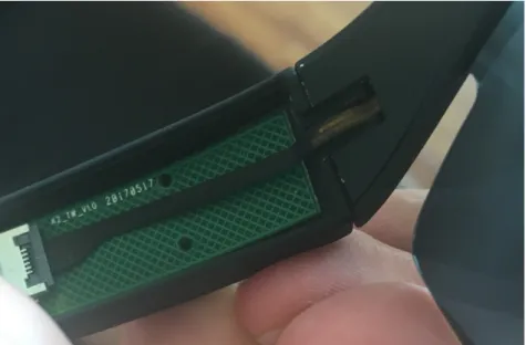
There are numerous smart eyeglasses that exist, but the designs we focused on are ones that have electronics running through at least two faces (i.e., the front and either arm). In this type of design, electronics need to run through a hinge, assuming the entire design isn’t rigid. This usually manifests itself as a set of flexible wires or a piece of flexible circuitry. A major issue with these designs is that the wires or flexible circuit are being subjected to dynamic bending and will experience fatigue as the glasses are repeatedly opened and closed, leading to an eventual system failure. The most ideal scenario would be to find a hinged electrical connector that can pass signals between circuit board and not require any circuitry to be repeatedly bent. We managed to find only one connector of this type and it was made by Molex (Figure 3-2) but we couldn’t find it on any online distribution websites. While touring Shenzhen’s electronic shops, we were told to talk to a specific shop owner whose speciality was knowing about and selling all types of connectors; a picture of his stall overflowing with connector reels is shown in Figure 3-3. After consulting with him and having him contact several factories that make Molex connectors, we unfortunately found out that this connector, or anything similar, was no longer in production and hasn’t been for a long time.
Given that we couldn’t get the connector, our alternatives were to either solder wires between the electronic subsystems or to have a flexible circuit run through the
Figure 3-2: Molex Hinged Connector
hinge which carries all the signal and power conductors. Since our system was going to have a variety of sensors, resulting in numerous signals and power lines running between the PCBs, soldering individual wires wasn’t a practical option. Therefore, we started to investigate design constraints for flexible circuitry in dynamic bending environments. We first started to disassemble various smart eyeglasses that we could find in the Shenzhen markets and within the factories that make them. We quickly found that most of the hinged designs had two pieces of plastic that were press-fit into each other with a piece of flexible circuit running somewhere between (Figure 3-4). The interesting note was that these designs did not follow the recommended guidelines for the minimum bend radius allowed in a flexible circuit, virtually guaranteeing eventual electrical failure within the hinge.
Figure 3-4: Flexible Circuitry Running Through Hinge of a Common Smart Eyeglass Architecture
To better understand what informs the minimum bending radius of a flexible cir-cuit, we talked to one manufacturer that specializes in these types of systems. Flexible printed circuit boards are comprised of several layers as shown in Figure 3-5. The thickness of a flexible circuit increases depending on the amount of copper electrical layers, polymide thickness, and copper thickness. For bending, the compressive and tensile forces increase the further you are from the neutral axis (i.e., center line) of the bend, resulting in tensile forces that if larger than the yield strength of the material, can crack the copper traces. In addition, apart from tensile forces, there are also shear forces within the flexible stack-up that can separate layers and lead to delami-nation of layers, particularly in the compressed regions. Therefore, it is important to
keep the thickness of the flexible circuit as small as possible in the bending regions to allow for greater electrical robustness over the life of the system. We’ve been told by manufacturers that for semi-dynamic bends (i.e., subjected to flexing less than 100 times), the minimum bend radius should be 20 times the thickness while for dynamic bends, the minimum bend radius should be 100 times the thickness.
Figure 3-5: Two Layer Flexible PCB Stackup [1]
Figure 3-6: Compressive and Tensile Forces in Bent Flexible Circuit [2]
Battery Architecture
Another tip we received from the manufacturers is that battery placement in the glasses is important for weight balance and power capacity considerations. Batteries are usually the most dense component in a pair of smart eyeglasses so their positioning matters due to weight distribution. If placed too far forward, the glasses can slip off
easily and if placed behind the ear, can lead to a less traditional aesthetic due to the battery’s large form factor. There are batteries with curved designs that can potentially go around the ear but those designs come at a trade-off of decreased power density and likely require custom manufacturing. Oftentimes, designers put a single battery on only one of the glasses (Figure 3-7) to simplify the design but that biases the weight towards one side and can lead to concentrated stress regions on the nose pad due to the mechanical moment imposed by the battery. The most ideal method would be to place two batteries, one on either side, to better balance the weight but this would lead to a more complicated power distribution architecture and charging circuitry.
Figure 3-7: Battery on One Side of Glasses
3.3
Sensor Selection
Through the design considerations outlined in Section 3.1 and with the valuable knowledge acquired during our design exploration discussed in Section 3.2, we were able to more easily narrow down the sensors for which to incorporate into our system. When selecting, we searched through much of the more recent literature on quantify-ing cognitive load and attention through physiological measurements, since that’s our target research focus. What was quickly apparent was that much of the more recent research has been focused on using electroencephalogram (EEG) on the frontal lobe of the brain to quantify a user’s attention. In fact, there have been several companies and researchers that use this technique for a mobile wearable, including BrainCo [46],
Muse [27], and AttentivU [47]. However, as described in Section 3.1.4, electrode-based techniques aren’t well suited for long-term use and during mobile activities so we decided to refrain from selecting this type of sensing technique.
We converged to having a non-contact temperature sensor (i.e., thermopile) on the nose since nose temperature has been used before to measure cognitive load [17]. However, since the nose temperature is also influenced by external stimuli (e.g., air flow), a baseline temperature measurement is needed. As a result, a second non-contact temperature sensor is positioned on the temple as a ground truth since the temple surface temperature is a good estimate for internal temperature and should not see rapid fluctuations during internal state changes [19].The second sensor we chose was an eye blink sensor, as cognitive load influences blink rate [13, 22]. To accurately measure blinks, we are using an IR emitter/receiver pair since its rela-tively low-power compared to camera-based approaches, its also non-contact, and has shown promise in detecting blink rate and intensity [24]. We also include an IMU, which allows us to capture a person’s activity level and head pose [48]. It has also been shown that a person’s head pose can be correlated with gaze direction which is important to determine what a user is fixated on in a controlled space [26]. Lastly, we adapt the system to be compatible with the VIVE Tracking System so that we can utilize existing hardware infrastructure for 3D location estimation, ideal for crowd applications and monitoring movement in a room. This will also allow us to deter-mine where a user is fixating by using the head pose and 3D localization data. The system also includes on-board user-noticeable LEDs that can subtly alert the wearer to any notifications (e.g., take a break, alertness is dropping, etc.), influence their attention, and, externally-facing for creative use in performances.
3.4
Design
The design of the system consists of three parts: the electrical, mechanical, and firmware. The electrical and mechanical design progressed in parallel since one in-formed the other. As mentioned in the acknowledgements, this was a joint effort between David Ramsay and I, with both of us collaborating on the initial planning, but him working primarily on the mechanical while I progressed on the electrical and firmware, with the exception of close collaboration on the light pipe design, which will be explained in the mechanical design section. A summary and comparison of our system with other popular smart eyeglass systems is shown in Table 3.1.
Table 3.1: System Specifications and Comparison
Design Target Captivates Google Glass Enterprise Edition 2 Focals by North
Weight 35g 46g 72.57g
Battery Life 10 hours <8 hours (depends on usage) 18 hours (intermittent use) Battery Recharge Time 3 hours 1 hour (fast charge) 2 hours Ruggedization None Water and dust resistant Water and dust resistant Sensing Modalities
∙Nose and Temple Temperature ∙Touch ∙Blink Rate ∙Inertial Measurement ∙3D Location ∙Microphone ∙Touch ∙Camera ∙Inertial Measurement ∙Microphone ∙Ambient Light ∙Inertial Measurement Actuators ∙Eye-facing LEDs
∙Externally-facing LEDs
∙Display Module
∙Mono Speaker, USB audio, BT audio
∙Display Module ∙Mono Speaker Price $100 (manufacturing cost only) $1000 $599
3.4.1
Electrical System
Circuit Layout
In order to maximize the amount of circuitry that can fit into a traditional eyeglass form factor, we decided to use a system design that uses 3 PCBs, one on either side and a flexible one running across the front and connecting to both side PCBs. The side PCBs would be a standard, FR4-core, circuit board at 0.8mm thickness so as to minimize the overall thickness of the eyeglass housing. We also design for 4/4mil copper spacing to allow for a compact circuit design. A picture of the unpopulated side PCBs is shown in Figure 3-8.
Figure 3-8: Unpopulated Side PCBs
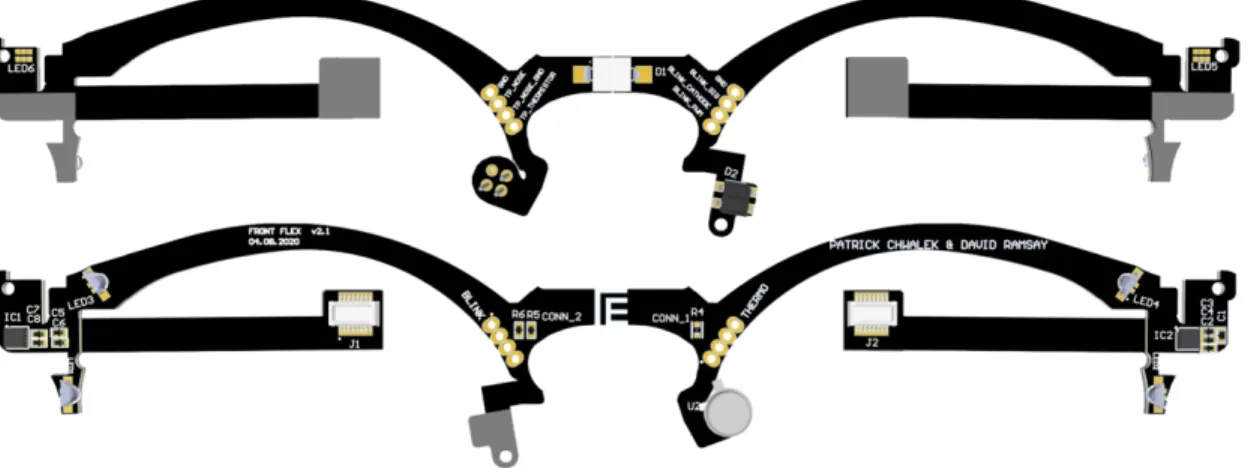
The front flexible circuit was the most novel piece of circuitry that we designed, since the circuit board needed to conform to the contours of the eyeglass’s front plastic housing and also needed to be robust enough for the dynamic bending experienced within the hinge. For the former, we designed a 3D rendering of the flex that had the correct curvatures (Figure 3-10) and then used computer-aided design (CAD)
software to unbend it to get the flat footprint (Figure 3-9).
Figure 3-9: Design of Flexible Circuit Board (Top is Front-facing, Bottom is Rear) As explained in Section 3.2.3, the thinner the flexible circuit is, the tighter bend ra-dius it can robustly tolerate. The issue we had was that we needed a four-conductive-layer flex PCB to be able to fit the amount of power and signal conductors we needed running across the glasses; if we chose to do a 2-layer design, that would dramatically increase the rim thickness of our glasses which would make the overall frame look bulky. With a 4-layer design, the minimum thickness that a manufacturer can guar-antee is 0.26mm, which per the 1:20 thickness-to-minimum-bend-radius ratio, would allow for a recommended 5.2mm radius bend, too large for any hinge design we could reasonably integrate.
After touring a flexible PCB manufacturing facility in China and becoming fa-miliar with the process, we came up with a nontraditional solution to increase the robustness of our circuit and allow for a tighter bend radius through the hinge. We settled on having the circuit board be 4-layers across the front of the glasses and then transition to 2-layers going through the hinge, a process we thought would be feasible when we watched a manufacturer assemble each layer of a flexible circuit. This 2-layer portion can be made as thick as 0.1mm, which would allow for a rec-ommended 2mm bend radius. To further improve the robustness, as also shown in Figure 3-10, the bend that we designed in the hinged area is an S-bend that is made by an initial static bend that can tolerate a tighter bend and gives space for a less extreme dynamic bend across the remainder of the 2-layer portion that is activated when the glasses are opened and closed.
One of the most complicated issues with this system was how to incorporate the sensors around the nose into the design. From a design perspective, the easiest
Figure 3-10: Curved Flex Circuit Rendering
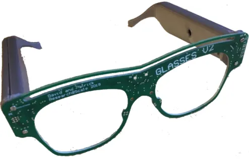
approach is to solder the near-nose sensors to the flex circuitry through a set of wires, but this method would significantly lengthen the assembly process. Instead, as we did with the entire flex assembly to match the contours of the glasses, we matched the bends of the flex circuit to that of the mechanical housing around the nose, creating two tails of flex circuitry that included the temperature and blink sensors. During installation, these tails are folded into the groves of the plastic housing, not requiring any additional soldering. The final manufactured flexible circuit is shown in Figure 3-11.
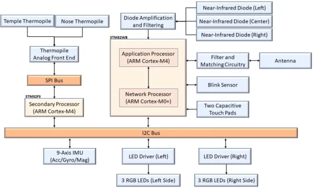
Processors
A block diagram of the entire system is shown in Figure 3-12. For the main proces-sor, we use a dual-core microcontroller (MCU) that has an ARM Cortex-M4 processor for the user application and an ARM Cortex M0+ processor for the network stack. This processor was chosen because it allows us to treat the MCU as an application processor, not worrying about the overhead of running the network stack. This ap-proach allows for quicker embedded firmware development and increased versatility for applications that don’t require the network component. In addition, this pro-cessor supports various types of network stacks (i.e., Bluetooth 5, Zigbee 3.0, and OpenThread) so if a different network architecture is required for an application, switching does not require a hardware redesign. Lastly, using this chip allows for a simpler electrical design than using two discrete processors (i.e., an application pro-cessor and network propro-cessor), since both cores are integrated into a single discrete package.
Figure 3-12: System Diagram
The dual-core MCU exists on one of the two-sided PCBs, which are separated and connected by the flexible circuitry. Given that sensors exist on all sides of the glasses and that the long separation between the two-sided PCBs can lead to signal integrity issues, we decided to put a secondary Cortex-M4 MCU on the opposite side
of the glasses. That way, this secondary MCU can manage the sensors on one side of the glasses, apply any preprocessing algorithms to its local sensor streams, compress the data, and send it to the main processor when ready or requested. Although this raises the software complexity, it allows us to simplify the hardware by reducing the amount of conductors going through the flexible circuit.
Power Architecture
Our system utilizes two batteries for better weight distribution, but this approach increases the complexity of our power architecture and charging circuitry. As shown in Figure 3-13, the lithium-polymer batteries and their charge controllers are electrically separated in our system until they are interfaced with our power multiplexer (MUX). The reason for the separation is that since the batteries are physically far apart (i.e., one in each arm) and since we cannot guarantee that they are from the same manufacturing batch, it is unsafe and ill-advised to put them in parallel for charging through one charge controller. For one, if they are not from the same batch, one of the batteries will likely age at a different pace than the other, leading to possible cross charging (i.e., one battery depletes into the other), resulting in a premature system failure. Also, this would constrain the design to always use the same capacity of batteries for both sides– a constraint we didn’t want in case there was an application where a larger density battery were to be tethered to one side. Another reason we went with the separated charge controllers is that with one charge controller and two spatially separated batteries, the two charge lines running to the batteries have to be impedance matched to ensure balanced charging, a constraint that would have been difficult to model given the complexity due to multiple connected circuit boards.
Within the multiplexer, the battery with the highest charge is prioritized over the other until discharged to around 0.2V under the idle battery. At that point, the comparator of the MUX triggers a switch and the idle battery is set to active while the active is made idle. If both inputs to the MUX are under 2.8V, the MUX goes into high impedance mode and shuts off the battery inputs and system output completely. This ensures that the batteries aren’t over depleted, which can result in damage to the batteries and potentially risking a hazard. The MUX output then powers two 3.3V, low-quiescent, linear regulators, one on each side of the system, and also directly powers the two LED drivers located on the flexible circuit.
Figure 3-13: Power Architecture Temperature
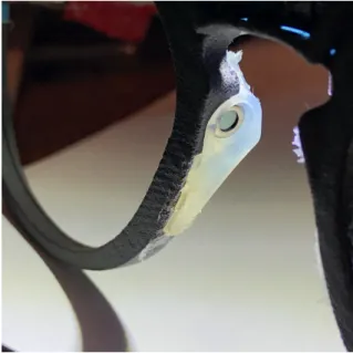
The thermopile circuit consists of two analog thermopiles, one faced towards one side of the nose (Figure 14) and the other faced towards the user’s temple (Figure 3-15). These thermopiles are then connected into an analog front end, which amplifies and filters the signal before being converted by the secondary processor’s 12-bit ana-log ADC. Once a set of readings is collected by the secondary processor, the main processor is alerted over an interrupt line, and after acknowledgement, the data is transmitted over the I2C bus to the main processor.
Figure 3-14: Nose Thermopile
Blink
The blink sensor is an IR emitter/receiver package that showed promising results in [24] on detecting blink events. We experimented with different blink detection locations and found that putting the sensor on the bridge of the nose, facing towards the eye, yielded the best performance. The near-infrared diode that emits light can be
Figure 3-15: Temple Thermopile
modulated through the main application processor to better dynamically adjust the reflected power seen by the receiving diode and enable synchronous detection. This feature is important for environments that have external near-infrared light sources (e.g., sunlight) that can saturate our blink sensor.
3D Localization and Pose Estimation
For the 3D localization, we are using two VIVE base stations [49] as our signaling sources in the environment in order to triangulate the glasses in 3D space. Each base station emits a vertical and horizontal near-infrared sweep, alternating between both sequences and between both base stations. Prior to each sweep, a pair of near-infrared LED flashes occur that signals to the receiver (i.e., the glasses) which base station is sweeping and if the sweep is horizontal or vertical. Ultimately, a set of four sequential sweeps (i.e., 1 horizontal and 1 vertical from each base station) repeats at a rate of 30Hz and is received by a near-infrared receiver. With the receiver being calibrated to know the global coordinates of each base station, it can determine where it is in 3D space by identifying the sweep and comparing the timing between sweeps. VIVE states that a less-than 2mm accuracy and a range of 16 feet can be achieved with their system, but based on preliminary testing we believe our tuned custom system can detect the base station sweeps at a range of at least 30 feet.
The hardware architecture for our receiver consists of three near-IR sensitive diodes, one on each face of the glasses. The search criteria for choosing which type
of diode to use consisted of finding a surface mount component that had a slim form factor but a large enough receptive area that also offered adequate responsivity to capture the momentary sweep. In addition, the field-of-view (FOV) needed to be large enough as to limit any blind spots. We evaluated six types of diodes and found that the VBPW34FASR by Vishay performed the best and conformed to our de-sign constraints. The three Vishay diodes in our circuit are then tied together (i.e., summed) and passed into a transimpedance amplifier to convert the diode-generated current into a voltage. The reason for the summation is that we wanted to treat the system as a point mass that has a large FOV so that as a person turns their head, at least one diode will still be exposed, increasing the reliability of the system. This also allows for a simpler analog front end with the trade-off of decreased accuracy, since the diodes are not spatially co-located but are treated as such in software. Although VIVE can achieve
For head pose, we chose a digital 9-axis IMU that connects to our I2C bus and of-fers various internally computed metrics, such as activity classification and a quater-nion matrix for estimating head pose. Software calibration was done to align the IMU’s reference coordinate system to the glasses coordinate system for accurate head pose estimation.
Other Components and Interactivity
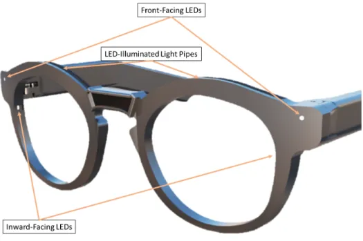
Our system offers a few other components for easy usability, interactions, and actua-tion. In order to easily program our system, we wired the USB micro port to both the battery charging circuitry and to the single-wire programming interface for the main application processor through a modified USB cable and an ST-Link Programmer— this can be done by anyone with just a programmer and a spliced USB cable. In ad-dition, the system has two capacitive touch points on the left arm that are sensitive enough to identify taps and both forward and backward swipe gestures. The sensitiv-ity of the touch points can be adjusted in software to tune for specific applications. Finally, as shown in Figure 3-16, there are six RGB LEDs, one facing towards either eye, two on the top, and two facing forward. The LEDs toward the eye are intended to be used as notification [50] while the other LEDs can be used for crowd applications (e.g., a concert where the LEDs are actuated by the person’s physiological signals).
Figure 3-16: LED Locations
3.4.2
Mechanical Design and Assembly
The mechanical design of the glasses has experienced several iterations as we con-verged on a final form factor. As outlined in Section 3.1.1, we wanted to choose a design that looks less like a research experiment and more like what most people would associate with a traditional pair of glasses. Figure 3-17 shows the front view of our most recent design. What can also be seen is an exposed opening above the bridge of the nose and two exposed openings, one on either side of the glasses (Figure 3-18). These openings are to expose the near-IR diodes to the incident light emitting from the VIVE base stations. Our goal is to cover these openings with near-IR transparent plastic, but for testing we’ve left them open for easy debugging. These openings can be covered or completely omitted for an application that does not require the 3D localization feature.
Hinged Design
We iterated on various hinge types, including omitting a hinge entirely and creating a rigid design. Eventually, we settled on an approach that is commonly found in smart eyeglasses, where the hinge is a plastic design with the flex circuitry running through the middle of it. Our flex circuitry is preformed (Figure 3-19) and inserted into the front housing, resting on internal raised plastic features (Figure 3-20). The flex circuit is then sealed by a piece of plastic acting as the back plane (Figure 3-21) and then
Figure 3-17: Front View
Figure 3-18: Angled View
the arm is able to be rotated around the flex circuit (Figure 3-22) and inserted into the plastic via a fastener running through the rotating axis of the hinge.
Light Pipes
One of the design features we were most excited about was to have the glasses include a hidden feature that allowed them to transition from normal day use to a more festive environment. To do this, we included a few RGB LEDs, including one on each brow that would light up the entire top ridge of the glasses. The goal was to have the illuminated features blend into the design so that when turned off, it wouldn’t be immediately apparent that this feature existed. One way we attempted to do this was by crafting a piece of polymethyl methacrylate (PMMA), also known as acrylic, to form a light pipe for the light from the RGB diode to transmit through. For our
Figure 3-19: Pre-bent Flex Circuitry
design, we needed the light to diffuse through the acrylic and evenly illuminate only one face while internally reflecting on all the others (Figure 3-23). We worked with a manufacturing facility in China to laser cut these PMMA pieces and chrome-coat three of the four sides to maximize the light emmission on the top-face (Figure ??). Although this method worked, we found it to be cost prohibitive given that a single piece cost us over $50 to custom manufacture.
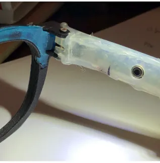
An alternative approach that we settled on was to use side-glow fiber optic cables. A traditional fiber optic cable is not suitable, since it lacks additional cladding on the cable’s surface that allows for greater diffusion of light across the length of the cable. Side-glow fiber optic cables, however, have a cladding, usually clear Teflon, that decreases the critical angle of incident on the internal surface that is required for external emission of light. Figure 3-25 shows the fitted 1.5mm diameter side-glow fiber optic cable illuminated in our design. Apart from the brow lighting, we also have lighting at two points on the front face of the glasses where some traditional glasses have rivets. To increase light visibility, we added commercial-off-the-shelf PMMA light pipes with fresnel lensing on one end so that the emitted light is less directed, offering better angular visibility.
Battery Placement
As we learned from our trip to Shenzhen (3.2.3), strategic battery placement was key to a more comfortable design. We have two, 150mAh, batteries on either side of the glasses, running in series with the side printed circuit board. The circuit boards are designed so that when assembled, the width is uniform across the batteries and across the circuit board assemblies for a streamlined design (Figure 3-26).
Figure 3-20: Inside of Front Housing
3.4.3
Firmware
For a system of this complexity, given all the sensor channels and preprocessing steps, it’s warranted to use some low-level operating system to help keep track of all the events, prioritize any events that need more real-time action, and provide the utility for easy debugging. To do this, we decided on using a real-time operating system that already has native support for the processors we are using and has a variety of tools that aid in debugging and in modelling the system’s performance.
FreeRTOS
FreeRTOS is a light-weight real-time operating systems that is capable of being run on microcontrollers and small microprocessors which makes it suitable for this project [51]. This operating system is also supported by ST Microelectronics, the manu-facturer of our processors, and has several additional tools written by ST Micro for easier system integration. FreeRTOS allows for the encapsulation of individual blocks of code into threads that can be triggered by a variety of sources (e.g., hardware in-terrupts, timers, other threads, etc.) and has various methods of passing messages across threads (e.g., queues, semaphores, mutexes, etc.). This encapsulation allows you to think of the firmware system as embedded blocks of code that have a deter-ministic operating behaviour. In addition, FreeRTOS offers various debugging tools
Figure 3-21: Sealed Front Housing with Flex Circuit Integrated
Figure 3-22: Adding a Side Leg
Figure 3-24: PMMA Light Pipe: Chrome-Plated (Top) and Non-Plated (Bottom)
Figure 3-26: Battery Placement in One Arm of the Glasses
that allow you to assess the memory and time utilization of the processor in real-time to model the system and determine if certain threads are causing delays or deadlocks. This allows for more efficient debugging since the problem can be quickly pinpointed to specific logical blocks.
As shown in Figure 3-27, there are a variety of threads in the system, all controlled by a master thread within each processor. The master thread receives queues from either the radio communication thread or inter-processor thread to enable certain sensor channels, actuators, or to send or receive messages. After enabling, each indi-vidual sensor channel is triggered by the hardware resource it uses for most efficient operation. For the blink sensing, the direct memory access (DMA) controller is used so that when sampling the blink sensor at 1kHz, the thread only awakens every sec-ond (i.e., 1000 samples) to preprocess and pass the data pointer to the master thread where the data is packaged for transmission. For inertial sensing, the digital IMU interrupts the processor when data is ready to be transmitted, triggering the Inertial Sensing Thread to start I2C transmission. The secondary processor also interrupts the main processor once it buffers 10 samples from each thermopile sampled at 10Hz and waits for an acknowledgement before sending the data over I2C.
3D Localization
The 3D localization code was adapted from prior work done in [5]. Every time one of the near-IR diodes is saturated by incidence light (i.e. rising or falling edge), an interrupt is triggered which results in a callback recording the exact timestamp of the event in microseconds. These timestamps are then fed into a thread that classifies if the event was part of a sequence (i.e., two flashes and a sweep) or if the event is noise. If part of a sequence, the code catalogs all the sweeps and calculates an estimate for the 3D location of the device. Since the code requires the global coordinates of the
![Table 2.1: Overview of the Direction of Temperature Variation in the Considered Regions of Interest Across Emotions [6]](https://thumb-eu.123doks.com/thumbv2/123doknet/14199059.479627/20.918.136.785.467.649/table-overview-direction-temperature-variation-considered-regions-emotions.webp)