HAL Id: ineris-00961760
https://hal-ineris.archives-ouvertes.fr/ineris-00961760
Submitted on 20 Mar 2014
HAL is a multi-disciplinary open access
archive for the deposit and dissemination of
sci-entific research documents, whether they are
pub-lished or not. The documents may come from
teaching and research institutions in France or
abroad, or from public or private research centers.
L’archive ouverte pluridisciplinaire HAL, est
destinée au dépôt et à la diffusion de documents
scientifiques de niveau recherche, publiés ou non,
émanant des établissements d’enseignement et de
recherche français ou étrangers, des laboratoires
publics ou privés.
First steps in coupling continuous carbon isotopic
measurements with already proven subsurface gas
monitoring methods above underground carbon dioxide
storage sites
Stéphane Lafortune, Zbigniew Pokryszka, Gaëtan Bentivegna, Carine
Chaduteau, Pierre Agrinier
To cite this version:
Stéphane Lafortune, Zbigniew Pokryszka, Gaëtan Bentivegna, Carine Chaduteau, Pierre Agrinier.
First steps in coupling continuous carbon isotopic measurements with already proven subsurface gas
monitoring methods above underground carbon dioxide storage sites. Energy Procedia, Elsevier, 2011,
4, pp.3526-3533. �10.1016/j.egypro.2011.02.280�. �ineris-00961760�
First steps in coupling continuous carbon isotopic measurements with already proven subsurface
gas monitoring methods above underground carbon dioxide storage sites
Stéphane Lafortunea, *, Zbigniew Pokryszkaa, Gaëtan Bentivegnaa, Carine Chaduteaub, Pierre Agrinierb
aINERIS (Institut National de l’Environnement Industriel et des Risques), B.P. 2, 60 550 Verneuil-en-Halatte, France bInstitut de Physique du Globe de Paris (IPGP), 1 rue Jussieu, 75 252 Paris Cedex 05, France
Elsevier use only: Received date here; revised date here; accepted date here
Abstract
The main role of INERIS (French National Institute for Industrial Environment and Risks) is to assess and avert accidental and chronic risks to both people and the environment linked to industrial installations, chemical substances and underground operations. INERIS is thus involved in research consortiums for underground storages of wastes, hydrocarbons or carbon dioxide. Concerning carbon dioxide storage, INERIS works for many years on defining and testing monitoring methods. As a French expert, the institute also performs integrated risk assessment studies.
This paper focuses on the last improvements concerning the monitoring methods developed or patented by INERIS.
Because the institute was created from the research centre of the former French national coal mining company, it has a well-established know-how in monitoring gas atmospheres. Having developed monitoring methods for mining contexts, INERIS has tools to constrain gas migrations in subsurface:
1. to determine gas flux between soil and atmosphere with dynamic accumulation chambers;
2. to determine gas concentrations in unsaturated zones through integrated gas sensor systems linked to subsurface boreholes (from 0 to about 300 meters depth).
Initially designed for mining context, these two methods have been tested and proven for the monitoring of CO2 geological storage contexts. For example between 2005 and 2007, INERIS was one of the five partners involved in the “GeoCarbone MONITORING” research project. This project was funded by the French Research Agency and aims at defining methods to monitor CO2 storage sites. Today the institute is involved in other projects studying pilot sites.
In this paper we present results collected in analog contexts to CO2 storage sites. We will discuss in which conditions the carbon isotopic signature 13C can help to determine the possible origins of the gas analyzed in our devices and to better understand the physical and chemical processes which can have led to the studied gas compositions. We will also highlight the fact that in some cases, there is a real need of using isotopic tracing methods otherwise the identification of these different processes cannot be done easily.
Keywords: accumulation chamber, carbon isotopic signature, CO2, gas flux measurement, gas monitoring
* Corresponding author. Tel.: +33 3 44 55 67 91 ; fax: +33 3 44 55 67 00
2
1. Introduction
INERIS has a strong expertise on gas monitoring in mining contexts. For several decades, INERIS uses its know-how to develop methods for the monitoring of CO2 geological storage sites [1] [2] [3]. Two specific approaches are
followed:
1. the detection and quantification of the gaseous flux of CO2 released from the ground into the atmosphere at
the soil-air interface;
2. the early detection of gas leak, based on the sampling and analysis of gas atmosphere in boreholes which are drilled into subsurface.
Gases from surface or subsurface are the results of mixing between different sources. This is for example the case for CO2 sampled at surface. CO2 can be atmospheric, be produced by plants respiration or come from anthropogenic
emissions (industrial activities). CO2 can also come from deeper sources such as volcanic sources, natural CO2 deep
reservoirs or CO2 storage sites…
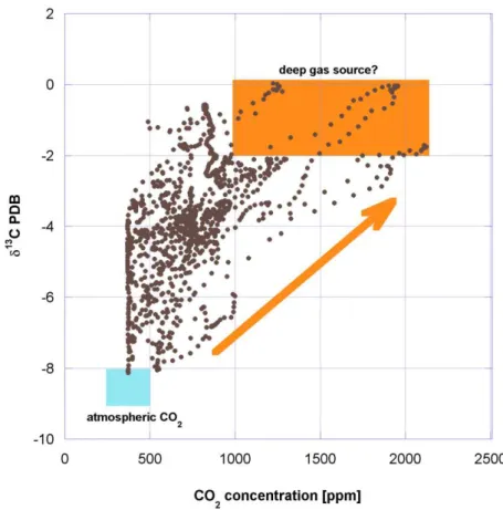
The analysis of the carbon isotopic signature of CO2 ( 13C, Fig.1 and Fig.2) can help to characterize the origins of
samples and to better understand CO2 production and migration processes. The identification of the origin of gas can
also be done through other ways, such as the analysis of trace gas [4].
Figure 1: Variations in carbon isotopic ratio are expressed as δ13C (in parts per thousand ‰) relative to the Peedee Belemnite standard (PDB).
Figure 2: Values of δ13C for naturally-occurring samples (image source: www4.nau.edu). Domain of values for volcanic CO 2 is in red.
INERIS has already used isotopic analyses (such as 15N, 18O or 13C) in mining contexts to better understand underground gas migration processes. We should now focus on the feasibility of improving monitoring methods developed for CO2 storage sites with isotopic analyses. At a first approach, the choice was made to work on the
determination of the isotopic signature 13C of CO2, because it seemed to be the most suitable and easiest method to
perform on field in the context of new technologies based on laser diodes.
The aim of this paper is to present first results and conclusions of coupling tests between the monitoring methods developed by INERIS and isotopic measurements performed at laboratory and on field.
2. Coupling gas flux measurements with isotopic analyses
First coupling tests between isotopic measurements and gas monitoring methods were performed during 2008. Samples were collected during repeated gas flux measurements at the surface of a site where natural volcanic CO2
emissions occur (Fig.3 and Fig.4). This site was studied as a natural analogue of future CO2 storage sites where gas
leaks would reach surface.
Gas flux measurements have been done according a method patented by INERIS [5].
Figure 3: Gas flux measurement on a volcanic site. Isotopic samples are collected with a syringe and stored in Exetainer vials.
4
The determination of the isotopic signature 13C has been done on gas samples collected by discrete sampling during gas flux measurements (Fig.4). 10-mL samples were collected with a syringe and injected in Exetainer vials every minute to follow the evolution of the isotopic signature during the increase of the gas concentration inside the accumulation chamber. Two kinds of Exetainer vials were used for this study: vials pre-filled with helium and vials under vacuum. Sampled volumes were chosen deliberately low to not interfere with gas flux measurements. Because accumulation chambers must stay about three minutes on the same place to perform a measure, at least three gas samples were collected for isotopic analysis at each gas flux measurement point.
Samples have then been analyzed for 13C of CO2 at IPGP, using a continuous-flow isotope ratio mass
spectrometer (Finnigan DeltaPLUS XP) interfaced to a Gas Bench modulus.
During gas flux measurements, the concentration of CO2 inside the chamber increases with time (from 400 ppmv
to about 7,000 ppmv). Isotopic analyses show a parallel increase of the carbon isotopic signature from an atmospheric value (about -8‰) to a higher value (about -6‰) (Fig.5). This higher value shows that CO2 which
migrates through the soil-air interface is enriched in 13C. For high CO2 concentrations, values of 13C which were
determined are fully compatible with a volcanic gas origin (Fig.2): there is a dilution process inside the chamber between the atmospheric gas and CO2 migrating through the soil-air interface. This result was expected due to the
geological context of the studied site (volcanic area).
Feedback teaches us that sampling with Exetainer vials pre-filled with helium ensures a better conservation of samples during sampling operations and transport/storage before analysis at laboratory. No flush of the vials was done on field before sampling. It seems that gas tightness of septum is better when sample is over-pressured compared to the atmospheric pressure. Gas from other sites (not discussed further here) were sampled by flushing 10-mL Exetainer vials with more than 50-mL of gas. This method, that is only possible when there is a large gas source, ensures that air initially in place within the tube is entirely removed before sampling (no risk of air contamination) and that the sample is at equilibrium with the atmospheric pressure (no risk of over- or under-pressured sample). According to other authors [6] flushing is the best way to ensure a good conservation of the samples.
Results confirm that isotopic measurements provide important information to determine the origin of the gas emitted from the soil. But an accurate field-deployable method appears to be required (1) to minimize risks of air contamination or gas leaking during sampling or transport/storage of the vials, (2) to reduce time between sampling on field and analysis at laboratory and (3) to increase the number of measurements.
3. Coupling gas monitoring in boreholes drilled in unsaturated zones with isotopic analyses
Gas monitoring in subsurface boreholes (between depths of about 5 to 100 meters) drilled in unsaturated zone shows that these systems can be quite difficult to characterize. As shown by continuous measurements, changes of the gas concentration profiles inside the boreholes can occur and be very difficult to understand.
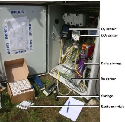
INERIS has developed methods to sample and analyze gas in boreholes drilled from surface into intermediate cap rock strata [3]: O2, CO2, CH4 and Rn concentrations in the atmosphere are continuously monitored by sensors (e.g.:
electrochemical or infrared sensors). Detection limit for CO2 is about 1 ppmv; for other gases it is about 0.1% and
100 Bq/m3 for Rn. To allow easy access to boreholes for other measurements, gas sensors are put on the surface, outside the borehole. A gas sampling loop pumps the gas phase at the bottom of the boreholes or just above the water table towards surface and injects it again in the well after analysis. By recycling the analyzed gas, the system reduces risks of contamination by atmospheric air (Fig.6).
Figure 6: Sensors system for gas monitoring in subsurface boreholes. Isotopic samples are here collected with a syringe and stored in Exetainer vials.
6
To better characterize gas concentration changes inside monitored boreholes, INERIS has sampled gas to determine isotopic signature 13C of CO2. Analyses are done at laboratory on samples collected in Exetainer vials or
Cali-5-Bond bags. This method leads to a discrete knowledge of the changes inside the boreholes. Thus, this method cannot be sufficient to describe correctly quick changes of the isotopic signature. When it can be implemented, a method allowing continuous isotopic measurements has to be preferred (Fig.7).
INERIS works for one year with the PICARRO G1101-i analyzer, a cavity ring-down analyzer for measuring the isotopic signature 13C of CO2. Gas is introduced into a high-finesse optical cavity and the optical absorbances of 12
CO2 and 13CO2 are determined. Because the absorbance of a gas depends on the nature of the gas and its
concentration inside the optical cavity, the analyzer provides concentration and isotopic ratio measurements [7]. Calibration of the analyzer is done by using gas mixings with known concentrations and known 13C.
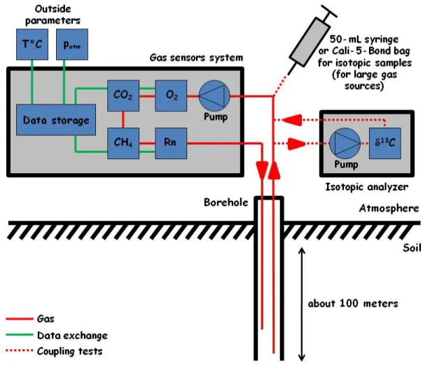
Figure 7: Principle of coupling the sensors system for gas monitoring in subsurface boreholes with discrete or continuous isotopic analyses.
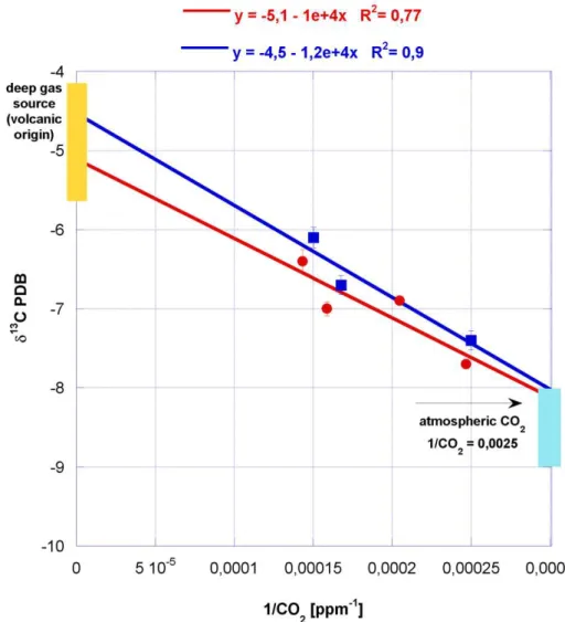
We present here the results obtained during the monitoring of a subsurface borehole for 5 hours (Fig.8). Variations with time of the CO2 concentration and the 13C of CO2 inside the borehole describe a gas mixing process
between two gas sources:
1. the surface atmosphere ([CO2] = 400 ppmv and 13C = -8‰);
2. an unknown CO2 deep source enriched in 13C. This source seems to be characterized by a CO2
Figure 8: Results (CO2 concentration and 13C) for continuous isotopic analysis during gas monitoring in a subsurface borehole.
First tests on field show that the use of the PICARRO G1101-i analyzer (1) simplifies field operations, by reducing numbers of gas samples to collect (but some samples are always useful to compare results between field measurements and some analyses done at laboratory); (2) increases the number of measurements; (3) reduces risks related to sampling, such as loss or contamination of samples during transport and storage before analysis at laboratory; and (4) limits the use of laboratory equipments which are free for other studies.
4. Conclusion
INERIS is studying the feasibility of improving surface and subsurface methods that were developed to monitor CO2 storage sites. The aim is to determine the carbon isotopic signature
13
C of CO2 at laboratory or on field, to
better characterize gas production and migration processes above CO2 storage sites.
Since 2008, different tests have been performed to couple isotopic measurements to the determination of gaseous flux of CO2 or the monitoring of the gaseous atmosphere inside boreholes.
These tests are helpful to define specific sampling procedures or experiment new analyzers. They are a first step before a larger application on CO2 storage pilot sites in the next years.
Acknowledgements
The authors thank Elodie Michel and Géraldine Cantor for their precious help on field and during the treatment of the results of the preliminary coupling tests.
This work was partially supported by the research project SENTINELLE funded by the French National Research Agency (ANR).
8
References
[1] Battani A, Deville E, Faure JL, Jeandel E, Noirez S, Tocqué E et al. Geochemical study of natural CO2
emissions in the French Massif Central: how to predict origin, processes and evolution of CO2 leakage. Oil and Gas Science and Technology (Revue IFP) 2010;65(4):615-633.
[2] Gal F, Le Pierres K, Brach M, Braibant G, Beny C, Battani A et al. Surface gas geochemistry above the natural CO2 reservoir of Montmiral (Drôme, France), source tracking and gas exchange between the soil,
biosphere and atmosphere. Oil and Gas Science and Technology (Revue IFP) 2010;65(4):635-652.
[3] Pokryszka Z, Charmoille A, Bentivegna G. Development of methods for gaseous phase geochemical monitoring on the surface and in the intermediate overburden strata of geological CO2 storage sites. Oil and
Gas Science and Technology (Revue IFP) 2010;65(4):653-666.
[4] Lafortune S, Moreira M, Agrinier P, Bonneville A, Schneider A, Catalette H. Noble gases as tools for subsurface monitoring of CO2 leakage. Energy Procedia 2009;1:2185-2192.
[5] Tauziède C, Pokryszka Z, Jodart A. Measurement of the gas flux from a surface. Patent EP0807822. [6] Tu KP, Brooks PD, Dawson TE. Using septum-capped vials with continuous-flow isotope ratio mass
spectrometric analysis of atmospheric CO2 for Keeling plot applications. Rapid Communications in Mass
Spectrometry 2001;15:952-956.
[7] Crosson ER. A cavity ring-down analyzer for measuring atmospheric levels of methane, carbon dioxide, and water vapor. Applied Physics B (Lasers and Optics) 2008;92:403-408.