Publisher’s version / Version de l'éditeur:
Vous avez des questions? Nous pouvons vous aider. Pour communiquer directement avec un auteur, consultez la première page de la revue dans laquelle son article a été publié afin de trouver ses coordonnées. Si vous n’arrivez pas à les repérer, communiquez avec nous à [email protected].
Questions? Contact the NRC Publications Archive team at
[email protected]. If you wish to email the authors directly, please see the first page of the publication for their contact information.
https://publications-cnrc.canada.ca/fra/droits
L’accès à ce site Web et l’utilisation de son contenu sont assujettis aux conditions présentées dans le site LISEZ CES CONDITIONS ATTENTIVEMENT AVANT D’UTILISER CE SITE WEB.
CIB IDS 2009: Improving Construction and Use through Integrated Design
Solutions [Proceedings], pp. 1-12, 2009-06-10
READ THESE TERMS AND CONDITIONS CAREFULLY BEFORE USING THIS WEBSITE. https://nrc-publications.canada.ca/eng/copyright
NRC Publications Archive Record / Notice des Archives des publications du CNRC :
https://nrc-publications.canada.ca/eng/view/object/?id=ce98572b-c032-45f2-b08b-4ad7a2ac8ecf https://publications-cnrc.canada.ca/fra/voir/objet/?id=ce98572b-c032-45f2-b08b-4ad7a2ac8ecf
NRC Publications Archive
Archives des publications du CNRC
This publication could be one of several versions: author’s original, accepted manuscript or the publisher’s version. / La version de cette publication peut être l’une des suivantes : la version prépublication de l’auteur, la version acceptée du manuscrit ou la version de l’éditeur.
Access and use of this website and the material on it are subject to the Terms and Conditions set forth at
Location tracking of prefabricated construction assemblies
http://irc.nrc-cnrc.gc.ca
Loc at ion t ra ck ing of pre fa bric at e d
c onst ruc t ion a sse m blie s
N R C C - 5 1 2 5 0
P a r d a s a n i , A . ; V a n t o r r e , L . ; D i c k i n s o n , J . K . ;
T h o m a s , J . R .
J u n e 2 0 0 9
A version of this document is published in / Une version de ce document se trouve dans:
CIB IDS 2009-Improving construction and use through integrated design
solutions, Espoo, Finland, June 10-12, 2009, pp. 1-12
The material in this document is covered by the provisions of the Copyright Act, by Canadian laws, policies, regulations and international agreements. Such provisions serve to identify the information source and, in specific instances, to prohibit reproduction of materials without written permission. For more information visit http://laws.justice.gc.ca/en/showtdm/cs/C-42
Les renseignements dans ce document sont protégés par la Loi sur le droit d'auteur, par les lois, les politiques et les règlements du Canada et des accords internationaux. Ces dispositions permettent d'identifier la source de l'information et, dans certains cas, d'interdire la copie de documents sans permission écrite. Pour obtenir de plus amples renseignements : http://lois.justice.gc.ca/fr/showtdm/cs/C-42
Location Tracking of Prefabricated Construction Assemblies
Ajit Pardasani, Laurent Vantorre1, John Dickinson, Russ Thomas
[email protected] [[email protected]] Center for Computer Assisted Construction Technologies
Institute for Research in Construction, National Research Council Canada 800 Collip Circle, London, Ontario, N6G 4X8
Canada
Keywords: prefabricated assemblies, tracking, integrated information flow, material handling,
construction
Abstract
This paper describes Internet based prototype tool for locating structural steel components at a construction site equipped with wireless Ethernet. The tool runs in a web browser on a notebook or on a Pocket PC and shows the location of an assembly on an aerial image or on a land survey. If the component being sought is not yet unloaded, it informs the user the trailer number and its location. This approach is based on the integration of location information with the component related information across the material handling process starting at the fabricators facility through the assembly of the building structure. Although the tool has been developed to assist the iron workers to locate structural steel, the concept is applicable to other prefabricated assemblies. The paper identifies the future research challenges and discusses different types of maps to assist users to help locate materials.
1. Introduction
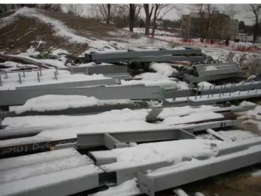
Construction of a large structure would typically require the handling of thousands of prefabricated construction assemblies at the fabricator’s site and at the construction site. As the assemblies move through the various work steps of being fabricated, stored, transported and erected, there is a substantial re-entry of data required at each step. Finding these assemblies, such as structural steel beams and columns shown in Figure 1, can be time consuming in large material storage lay-down yards such as found either at the fabricator’s site, or at the construction site. It can be especially so if assemblies are covered in the snow or hidden by vegetation. Time spent in searching for the assemblies and the related information is time wasted and has a negative impact on the construction workers productivity. This waste can be reduced if the latest information regarding the status of assemblies, its attributes, and location can be found at any work step and can be accessed from anywhere. This will not only help reduce the time to locate assemblies as they move through the work steps but will also support planning decisions that are location dependent.
1
Figure 1: Finding snow covered components could be very frustating
Most general contractors, sub-contractors, material suppliers, and sub-assembly manufacturers still rely on paper-based systems to track prefabricated assemblies. The lay-down yards are divided into zones and the location of materials is recorded in a paper notebook. There could be several people, each having a separate paper pad for recording the location information. Finding the location of a desired assembly by flipping through the pages of multiple paper notebooks is time consuming and could often be very frustrating. Not only is the current practice labor intensive and inefficient but it is also error prone due to incomplete information, illegible handwriting, and spelling mistakes. Moreover, the location data is not easy to update as in most lay-down yards the construction assemblies have to be moved from location to location multiple times before being finally erected.
Unfortunately, there is little academic research data available on the economic impact of applying material tracking. Torrent and Caldas [6] note that craft labour hours are increased by 16-18% due to material not being ready and that, based on other published works, workers can waste up to a third of their working time searching for materials. More colloquial evidence can be found in industry periodicals. An article by Sawyer [4] on a recent case study notes the cost benefits involving two similar industrial construction projects comparing the use of an automated material tracking system versus a manual system for a lay-down yard. The results were sufficiently compelling, after the initial stages, that the case study was stopped early to allow both projects to proceed using the material tracking technology. Times to manually track items were averaged about 36.8 minutes versus only 4.6 minutes using the automated system. Furthermore, almost 10% of the items sought manually “were not immediately found”, in comparison to only 0.54% using the automated system. In another article [3], Sawyer notes that the time saved as a result of knowing where precast members were and controlling the sequence of use saved about 10 days on a project equating to $1 million. Academic researchers have been interested in the problem of tracking construction materials for some time. One early example is the work done by Lundberg et al. [2]. They built a system where the user was presented with a CAD model of the lay-down yard and construction site with the location of the construction material. The system integrated radio networked hand-held bar code readers, a custom local multi-antenna radio transmission-based triangulation system which tracked beacon-equipped transport
equipment, and a server computer to record material movement and other data. A significant amount of manual work was required to scan and initiate location data recording during each material movement and the manual creation of the initial CAD representation of the site. Their solution depended on the use of a custom position tracking technology making adoption of their approach by others difficult and expensive. A decade later, Stone et al. [5] developed a system capable of tracking material in lay-down sites including location and orientation of the material. Their approach made use of both RFID and bar code technologies for tagging the material being tracked and wireless communication with portable computers to communicate with workers in the field. By providing web-based access and updating of temporal databases recording material status and the recording of both position and orientation of the material after each transition, the system is capable of capturing data for as-built documentation. In order to capture the spatial orientation of each object, CAD models of all parts being tracked were required, and operators were required to gather accurate measurements of at least three “fiducial” position points (points defining the orientation of the material in 3D space) using specialized tracked equipment after each material movement. The authors’ note that usually this process takes only 30 seconds but this doesn’t take into account the time required for first unloading from the transport equipment and then long items, like beams, will also take significantly longer for the operator to walk around and measure each of them. This can be considered a major impediment to technology adoption even though the eventual pay off could be accurate as-built models.
Research work in this area remains very active for industrial construction applications [6] with current approaches making use of modern active RFID tags, networked GPS-equipped sensors mounted on mobile equipment and localization algorithms to refine position information based upon multiple remote material detections. Localization algorithms are required to extrapolate likely material positions based on multiple sensor readings by RFID readers installed on GPS-equipped vehicles that drive around the yard to scan and record the signals from the active tags. The broader the range, the more likely every material tag will have been sensed but the more difficult it is to narrow down the precise location. Thus, selection of RFID signal response strength limits requires making a trade-off. One draw-back to this approach is the use of active sensors costing about $30 each, making this approach more likely in bigger capital projects.
Though the enabling technologies for tracking of materials such as bar codes, RFIDs, GPS, etc. have been around for some time, the adoption by the construction industry has been very slow. Tracking of components through computer systems, with varying degree of automation, is very common in the manufacturing industry, whereas the same cannot be said for the construction industry. There are two major reasons; one is that, traditionally, the construction industry has been slow to adopt information technology solutions, and the second being that implementing tracking in the construction industry is much more challenging due to the harsh outdoor conditions and uncontrolled environment. Unlike in manufacturing and warehouse applications where the materials are stored indoor with components or pallets organized in racks, most construction materials are stored outdoors, on the ground. Tracking solutions very much depend on how the materials are tagged, handled and stored. Therefore, the solutions for the construction industry must work reliably and accurately in all types of weather, ranging from the hot summers to cold winters, from bright daylight to night illumination, and from rain to snow. The harsh outdoor conditions, combined with the storage scheme ranging
from free form to pre-designated zones or grids on the ground, makes implementation of reliable and accurate material tracking a very difficult problem in construction industry. The approach presented in this paper contributes to the Integrated Design Solutions (IDS) vision of CIB by showing that the problem of process inefficiencies in the materials management in construction industry can be addressed through the data integration and information management across the worksteps ranging from fabrication to installation of materials. The inefficiencies in tracking of materials arise as the latest and accurate information regarding the status of location of materials is not readily available. The economic benefits of materials tracking system can only be fully realised when it is integrated with the design, manufacturing, quality control, and materials handling work processes. The isolated development and deployment of just the material location tracking will only bring very limited economic benefits and may require manual re-entry of some data that may exist in some other system, for example weight of assembly, measurements, job number, etc to populate the database. Whereas a fully computer-assisted integrated tracking system will eliminate the manual data re-entry by integrating the data from other work units of the organization such as design, scheduling, manufacturing, quality control, and yard management. This integrated system will enable better coordination between the work processes leading to better planning of material handling operations culminating in higher efficiencies. The vision of IDS to achieve the integration between different phases of project throughout the whole life cycle when applied to the materials tracking would mean improving the communication regarding the status and location of materials with all the parties in the supply chain including the fabricators, general contractor, and sub-contractor. A materials tracking system integrated across the supply chain would enable all parties to query the latest status and location of materials thus resulting in better planning across the project organization.
2. Integrated Tracking Tool
Finding the structural steel components at the lay-down yard of a large construction project can be time consuming. The current practice for the material handling of a steel framed building is that the structural steel components are received at the project site in trailers and unloaded to the ground as shown in Figure 2. The number of trailers that are simultaneously unloaded depends on multiple factors such as the size of the construction site, and the urgency to free up the loaded trailers for other projects, etc. After unloading, components are then quickly organized on the ground such that piece marks are visible to the iron workers. This step is known as the shakeout.
The foreman of the erection crew refers to the erection drawings and expects the arrival of the structural steel members in the order in which they are to be erected and he/she creates a list of piece marks on a paper notebook. The list is then used by the ground crew to search the steel members needed next. There are many instances when the search results are negative because the component has either not been shipped from the factory or has not been unloaded from one of trailers parked at the site. In such situations iron workers search more thoroughly on the ground and this can take several minutes depending on the size of the site. A material tracking tool that will help locate the components from the factory shipment to the storage yard will help increase efficiency by reducing the wasted search time.
Figure 2 : Top left picture shows the steel assemblies received at a construction site on trailers. Bottom left shows the steel columns after unloading and shake out. The right picture shows the erection of a column.
The Centre for Computer Assisted Construction Technologies (CCCT), a part of the National Research Council’s Institute for Research in Construction, is conducting research on how best to apply information technologies to address issues facing the construction industry. One of the key issues is construction sector productivity. Research is under way to develop tools for the tracking of prefabricated assemblies, for example, structural steel and precast concrete assemblies, to increase the efficiency of the material handling work process. A prototype tool has been developed to help a steel erection crew locate beams and columns quickly in the yard by integrating design and material handling processes with Geographical Information System (GIS) and GPS technologies. The tool runs on any standard Internet Browser, either on a desktop or mobile PC. Although the tool was developed for tracking of structural steel, the concept applies to other construction assemblies as well.
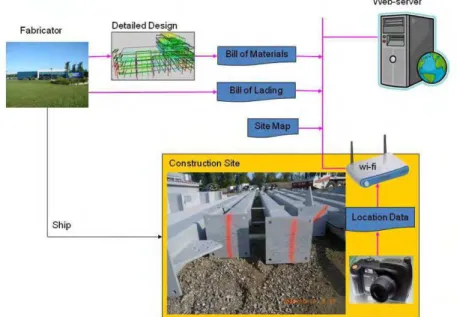
The conceptual architecture of the system is illustrated in Figure 3. The system is hosted on a web server and integrates the data from the design, bills of lading, and the actual location. The Assembly List shown in Figure 5 is exported from the steel fabricator’s design model using NIST’s CIS/2 to VRML translator (http://cic.nist.gov/vrml/cis2.html). Most design tools for the steel framed buildings, e.g. SDS/2 from Design Data and Tekla Structures, support the export of design in CIMSteel Integration Standards version 2 (CIS/2) format which enables the seamless and integrated flow of information amongst all parties of the steel supply chain for the steel-framed buildings. The system takes Bill of Lading information as the second input and a geo-referenced map of the lay-down yard is used as the third input. The system uses Google Maps API and an aerial picture or a map (e.g. land survey) of the site to show the location of a steel assembly by displaying a marker like a balloon or a pin. If an
aerial picture or a map has to be used, it needs to be geo-referenced by assigning corresponding geospatial coordinate values to all its pixels. This is achieved by using a GIS system and involves establishing control points for which the geospatial co-ordinates are already known. In most situations the property survey for the storage yard or the construction site should exist and could be geo-referenced for use in the system. The location information for steel assemblies is captured through a GPS camera.
Figure 3: Conceptual Architecture showing the data integration from diverse sources such as bill of materials, bill of lading, site map, and location data
The current industry practice is to identify the steel assemblies by marking the identification number on beams by either painting them with a handheld paint brush or with a marker pen. The columns are identified with engraved metal tags that are attached to the base plate as shown in Figure 4. The bar codes and RFIDs have still not found widespread use amongst steel fabricators. So that the tracking system is in conformance with the existing industry practice of painting the piece marks on steel assemblies, we have used a digital GPS camera (Ricoh 500SE has a GPS unit attachment that uses SiRFstar III chip) as a field data collection device to record the geo-coordinates of the location of the camera when the picture of the piece mark is taken. The camera embeds GPS coordinates in digital images by automatically storing the GPS coordinates in the image EXIF header. The GPS data can later be extracted from images using an application program capable of reading and parsing the EXIF data.
Figure 4: One of the steel beams on the left picture is marked as 6B4 for "DIV 2" erection sequence for the project identified as 10406. The right picture shows a column labeled with a circular disk tag with the identification number 22C1.
The usage of the system would require that the ground crew takes pictures of the piece marks on steel assemblies after the shake out. If the construction site or the storage yard has Wi-Fi connectivity, the pictures can be downloaded to the server immediately through the built in Wi-Fi in camera or else could be downloaded later. The user then uses GPS-Photo Link, an application program from www.geospatialexperts.com, to associate piece marks to the corresponding geo-location. This is currently done manually as the user enumerates through the pictures, one at a time in the scrollable list, reads the piece mark, and types the piece mark in the text field. The process of enumerating over the pictures takes only a few minutes and results are saved in a file which is uploaded to the web server. The tracking application program on the server parses the assembly list, bill of lading, and the geo-location information and integrates the data to display the attributes of the component and its location on the ground.
Figure 5: Partial view of the assembly list exported out into a spreadsheet from NIST’s CIS/2 to VRML translator
The user interface for the tracking tool consists of a table on the left side and the map to its right as shown in Figure 6. It runs on a standard Internet Browser. To find the location of an assembly the user scrolls through the table and selects its piece mark to see the location on the map. If the quantity of the assembly selected is more than one, then the location of all pieces is shown.
Figure 6: Tracking Tool for Prefabricated Assemblies. The left picture shows the location of the components in an aerial view and the right picture shows the locations on the Google Maps satellite view. The aerial picture is taken by an aircraft flying at a low altitude. Piece mark 13b6 is selected on the table on the left and the location of all corresponding three assemblies is shown on the map.
The ground crew can also choose to locate components on the site survey view as shown in Figure 7. Each construction site or a storage yard has a site survey and it can be geo-referenced and integrated to the tracking tool for helping visualize the location of components.
Figure 7: Locating assemblies on a site survey
Apart from assisting in finding the location of an assembly on ground, the tracking tool informs the user if the assembly is still in the trailer and has not been unloaded to the ground. This way the user knows that the desired assembly is still on the trailer, including the trailer number, and does not have to waste time searching for it in the yard.
3. Conclusions
This paper has demonstrated the integration of design data and the bill of ladings within the framework of location tracking. The integration with the design data helps the field crew to know the major attributes such as weight, length, and width, etc. This awareness helps in identifying the desired parts quickly from a distance as the field crew gets closer to the indicated location. Integration with upstream applications such as scheduling and fabrication will help in finding the manufacturing status of a part. Moreover, the performance of the whole materials handling system can be optimized by integrating the location data to other decision support systems such as crane dispatching, routing, materials storage layout [1], etc.
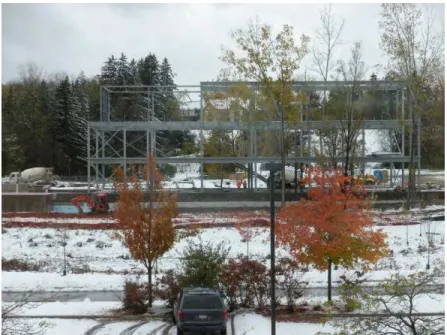
The initial testing of the tool by the researchers at a 60,000 sq. ft. green building construction project at the University of Western Ontario Research Park, shown in Figure 8, has shown that assemblies are quickly located by looking at the location markers on the map. When the foreman of the iron workers was shown the three alternatives maps of the site, the preference was shown for the aerial view and the site survey. The satellite view was not found to be very useful due to the outdated picture as the ground features no longer correspond to the satellite picture. During the early phases of the construction project, the ground features at the site undergo dramatic change as the foundation walls are poured and the security fence is installed around the site. Trailers for temporary project offices make other important landmarks at the site. These important landmarks are used by ground crew as mental reference points to locate assemblies whose location is shown on the map. Aerial pictures, when taken after the foundations are completed, can be useful, possibly until the completion of the project. The land surveys, an example shown in Figure 7, are equally useful since they show the footprint of the building. One added advantage of land survey documents is that landmarks can be added or removed by editing the CAD file. This way, the map can be kept current with the site conditions as the project progresses. Initial feedback, from the trades at the construction project, indicates acceptance of the site surveys and puts it at par with the aerial pictures in terms of its usefulness. The most important factor in selecting a map should be whether it shows a sufficient number of highly visible land marks. On a small construction site the footprint of a building and the trailers may be enough but a large lay down yard or a storage yard would need a sufficient number of highly visible landmarks or zones to help the field crew in locating the item with the help of maps.
Since the structural steel assemblies are large and the piece marks are visible from a distance, the maximum rated accuracy of 5 meters obtained from most consumer grade high sensitivity GPS chips such as SiRFstar III is mostly sufficient to locate large structural steel pieces. Since the piece marks on the structural steel components are large and can be read from a distance, very high location accuracy was not essential. In case, if only bar codes were to be used instead of highly visible painted piece marks, sub meter level accuracy location devices would be highly desirable to quickly find the piece. We observed that the usefulness of the tool in quickly getting to the desired steel assembly is dependent on the number of factors such as, size of the yard, numbers of assemblies in the yard and its spread density, and size of individual assemblies. The larger the search space and number of items to be searched, the greater the time savings.
Figure 8: Erection of a 60,000 square feet office steel framed building
We also found that the ability of computing hardware to withstand the rugged outdoor conditions such as bright sunlight, rain, snow, very cold temperatures and dust will govern whether tracking technologies actually get used at the construction work sites and storage yards. One of the major challenges in using the computers outdoors is the ability to read the screens in bright daylight. Notebook computers for home and office use have transmissive display screens that have a luminance of 250 nits or less which is sufficient for indoor use, whereas outdoor screens must have a much higher luminance value of 500 nits or more. Most notebooks that have outdoor displays are also ruggedized, made to military specifications to withstand shocks and harsh environmental conditions. These are therefore not only many times more expensive than their indoor counterparts but are heavier and not easy to carry, whereas, mobile computing hardware, such as mobile computers and smart phones, can be used outdoors and are rapidly advancing in computing power, ease of use, while becoming affordable at the same time. Their small size makes them easy to hold in the palm of the hand and with when used with ruggedized casings make them good for outdoor use. Though not work horses for computing, smart phones are beginning to offer good functionality for inputting and receiving small chunks of data over the Wi-Fi or wide-area cellular telephone networks such as 3G. The blue tooth connectivity enables integration with other devices such as GPS, bar code readers, RFID readers and with relative ease. More smart phones are coming out with touch screen interfaces such as Samsung Omnia and some with both touch screen and keyboard such as Google Android. With newer and faster processors, larger memory, user friendly interfaces, integrated GPS, Wi-Fi, blue tooth, and 3G, the future smart phones have the strong potential for use in construction industry.
Though the location data collection through a GPS camera works well with the structural steel assemblies as these have hand painted piece marks, it is more suitable for slow moving inventory. The construction sites and storage yards are dynamic in nature, with materials continuously arriving and leaving. Moreover, the materials may also get moved around in the yard to approach and retrieve those that may be surrounded by others. For example, in order to get to the desired assembly, the parts that are either
stacked on top or lie in very close proximity have to be relocated. Therefore, a computer-based tracking system will find wide acceptance by the field crew if the location data is not only accurate but is kept current at all times. This necessitates that the location data is collected in an automated way as the parts and assemblies arrive, leave, or are relocated in the yard.
Though large structural steel assemblies are not stacked in layers at the project site, there are other types of assemblies such as precast concrete elements that are stacked in layers at storage yards as shown in Figure 9. Finding the vertical position of a piece in a stack through automation is a challenge through current localization technologies as the accuracy needs for determining the vertical position are higher as compared to that of the horizontal. A fully automated materials tracking system must have the capability to find the exact layer in which the assembly is stored.
Figure 9: Precast concrete elements stacked in layers
Figure 10: Tracking of prefabricated assemblies indoors, either at a fabricators warehouse or at a construction site, poses difficult challenges. Left picture shows structural steel assemblies at the fabricators warehouse awaiting shipment. The picture on the right shows the doors and windows assemblies at a construction project.
Not all the construction materials, even large assemblies, are stored in outdoor environment. For example, structural steel assemblies after fabrication and painting could be stored indoors awaiting shipping as shown in Figure 10. There are much greater practical challenges for tracking construction materials in indoor environments as indoor localization technologies for are not very accurate.