Authenticated storage using small trusted hardware
The MIT Faculty has made this article openly available.
Please share
how this access benefits you. Your story matters.
Citation
Hsin-Jung Yang, Victor Costan, Nickolai Zeldovich, and Srinivas
Devadas. 2013. Authenticated storage using small trusted hardware.
In Proceedings of the 2013 ACM workshop on Cloud computing
security workshop (CCSW '13). ACM, New York, NY, USA, 35-46.
As Published
http://dx.doi.org/10.1145/2517488.2517494
Publisher
Association for Computing Machinery (ACM)
Version
Author's final manuscript
Citable link
http://hdl.handle.net/1721.1/86161
Terms of Use
Creative Commons Attribution-Noncommercial-Share Alike
Authenticated Storage Using Small Trusted Hardware
Hsin-Jung Yang, Victor Costan, Nickolai Zeldovich, and Srinivas Devadas
Computer Science and Artificial Intelligence Laboratory Massachusetts Institute of Technology
Cambridge, Massachusetts, United States
{hjyang, costan, nickolai, devadas}
@mit.edu
ABSTRACT
A major security concern with outsourcing data storage to third-party providers is authenticating the integrity and freshness of data. State-of-the-art software-based approaches require clients to main-tain state and cannot immediately detect forking attacks, while ap-proaches that introduce limited trusted hardware (e.g., a monotonic counter) at the storage server achieve low throughput. This pa-per proposes a new design for authenticating data storage using a small piece of high-performance trusted hardware attached to an untrusted server. The proposed design achieves significantly higher throughput than previous designs. The server-side trusted hardware allows clients to authenticate data integrity and freshness without keeping any mutable client-side state. Our design achieves high performance by parallelizing server-side authentication operations and permitting the untrusted server to maintain caches and sched-ule disk writes, while enforcing precise crash recovery and write access control.
Categories and Subject Descriptors
D.4.6 [Security and Protection]: AuthenticationKeywords
Secure storage; Trusted hardware; Authentication; Integrity; Fresh-ness; Replay attack; Forking attack
1.
INTRODUCTION
Cloud-based data storage services are becoming increasingly pop-ular, allowing users to back up their data remotely, access the data from any connected device, as well as collaborate on the shared data. For example, Amazon S3 [1] and Google Storage [17] offer scalable storage services to end users, enterprises, and other cloud services providers. Dropbox [10], Apple iCloud [2], and Google Drive [18] further provide file sharing and synchronization services among multiple devices and users. The outsourced data storage ser-vice provides users convenience and global data accessibility at low cost, and frees them from the burden of maintaining huge local data storage.
Permission to make digital or hard copies of all or part of this work for personal or classroom use is granted without fee provided that copies are not made or distributed for profit or commercial advantage and that copies bear this notice and the full cita-tion on the first page. Copyrights for components of this work owned by others than ACM must be honored. Abstracting with credit is permitted. To copy otherwise, or re-publish, to post on servers or to redistribute to lists, requires prior specific permission and/or a fee. Request permissions from [email protected].
CCSW’13,November 8, 2013, Berlin, Germany. Copyright 2013 ACM 978-1-4503-2490-8/13/11 ...$15.00. http://dx.doi.org/10.1145/2517488.2517494.
Although there are powerful economic reasons to adopt cloud storage, outsourcing data introduces some potential risks, typically thought of in terms of confidentiality, availability, integrity, and freshness. These risks arise due to many factors, including mali-cious attacks on the storage provider, insider attacks, administra-tive mistakes, or traditional hardware failures. Most of these con-cerns can be resolved by software: confidentiality by encryption, availability by appropriate data replication, and integrity by digital signatures and message authentication codes. On the contrary, it is difficult to ensure freshness in software when there are multiple clients involved.
Freshness requires the data read from a server to match the lat-est write, and it is difficult to enforce in software because it requires knowing about all possible writes that the server may have acknowl-edged. With a naïve client that has no client-side mutable state, a malicious server can perform a replay attack by answering the client’s read request with properly signed but stale data. This attack can be detected if the client remembers the last operation he/she has performed [23]. In the presence of multiple clients, a server can “fork” its state to prevent one client from seeing another client’s writes, and detecting such attacks requires one client to learn about the other client’s writes out of band [23].
To detect forking attacks, software-based solutions [6, 33, 24, 12] require user-to-user communication and thus cannot achieve immediate detection. Hardware-based solutions [8,22,36], on the other hand, add a piece of trusted hardware to the system. The trusted hardware typically provides a secure log or a monotonic counter, preventing a malicious server from reversing the system state to its previous value or presenting valid but inconsistent sys-tem states to different users. However, such trusted hardware is of-ten resource-constrained, and becomes a performance bottleneck.
To improve the performance of trusted hardware while keeping the cost low, Costan et al. in a position paper [9] proposed splitting the functionality of the trusted hardware into two chips: a P (pro-cessing) chip and an S (state) chip. The P chip has high computing power to perform sensitive computations, and the S chip has secure non-volatile memory (NVRAM) to store the system state. How-ever, Costan et al.’s design does not address two possible attacks that can violate integrity and freshness guarantees: (1) a server (or other malicious users) can pretend to be a legitimate user and per-form unauthorized/replayed writes without being detected, and (2) a server can maliciously discard the users’ updates that are already acknowledged by disrupting the P chip’s supply power and reset-ting it with the stale state stored on the S chip. Prior work also does not address the key challenge of crash recovery: a server that crashes before data is written to the disk may be forced to stop providing service altogether, due to the inconsistency between the disk and the state stored on the S chip. Furthermore, to our best
knowledge, neither results nor implementation have been provided to prove whether split trusted hardware achieves high performance. In this paper, we rectify the security vulnerabilities in the S-P chip model proposed by Costan et al. and provide a detailed de-sign augmented with a precise write access control scheme and sys-tem state protection against power loss. In addition, we propose an efficient crash recovery mechanism to improve system reliabil-ity. To prove our design achieves high performance while ensuring data integrity and freshness, this paper presents a full-system im-plementation and end-to-end evaluation of the proposed system for authenticated storage. Our system achieves high throughput by par-allelizing the operations carried out on the server and the P chip and permitting the untrusted server to manage caches and schedule disk writes to optimize disk I/O.
We implement our prototype trusted hardware on an FPGA and connect it to a Linux server. A client model is also implemented in Linux and it runs an ext2 file system on top of our authenti-cated block storage. We demonstrate that (1) our system perfor-mance is comparable to that of the Network File System (NFS) [31, 32] and (2) the security mechanisms introduce little performance overhead—around 10% for typical file system benchmark work-loads under a realistic network scenario. In addition, we provide customized solutions based on micro-benchmark results: (1) For performance-focused storage providers, our design can achieve 2.4 GB/s throughput using an ASIC paired with a smart card chip; (2) For budget-focused storage providers, our design scales to a single-chip solution that is feasible under today’s NVRAM process and can achieve 377 MB/s throughput, which is much higher than that of other existing single-chip solutions [36]. This single-chip solu-tion does not follow the high-level concept proposed in [9].
The main contributions of this work are as follows:
• A detailed design and implementation of a trusted hardware platform that provides integrity and freshness guarantees and achieves high throughput and low latency.
• A state protection scheme that tackles the security vulnera-bility caused by power attacks on the split trusted hardware. • A write access control scheme that prevents unauthorized
writes from violating integrity and freshness guarantees. • A crash recovery mechanism to protect the system from
acci-dental or malicious crashes, which both allows the untrusted server to schedule disk writes and still provides strong fresh-ness guarantees.
• An end-to-end evaluation that shows our design introduces little overhead on file system benchmarks.
• A single-chip solution of our prototype is shown to achieve much higher throughput than existing hardware solutions. The rest of this paper is organized as follows: Section2presents the related work. Section3provides an overview of our system, and Section4describes its design. Implementation details and opti-mizations are discussed in Section5. Section6evaluates the system performance. Section7concludes the paper.
2.
RELATED WORK
To ensure data integrity by detecting unauthorized data modifica-tion, cryptographic hashes, message authentication codes (MACs), and digital signatures are commonly adopted in current systems [15, 21,29]. In addition, fine-grained access control is needed to sepa-rate the writers from the readers in the same file. For example, in Plutus [21], each file is associated with a public/private key pair to differentiate read/write access. For each file, a private file-sign key
is handed only to the writers, while the readers have the correspond-ing public file-verify key. When updatcorrespond-ing the file, an authorized writer recomputes the hash of the file (which is the root hash calcu-lated from the block hashes using the Merkle tree technique [27]), signs the hash with the file-sign key, and places the signed hash in the file header. Then, readers can check the integrity of the file by using the file-verify key to verify the signed hash.
Freshness verification of outsourced storage is more challenging, especially when serving a large number of clients. When issuing a read request to a cloud server, a client cannot detect the server’s mis-behavior using the signature verification scheme mentioned above if the server performs a replay attack by maliciously sending the stale data with a valid signature from an authorized user. This kind of attack can cause freshness violations.
In a single-client setting, a replay attack can be detected if the client is aware of the latest operation he or she has performed. Cryp-tographic hashes can be used to guarantee both integrity and fresh-ness. A naïve approach is to store a hash for each memory block in the client’s local trusted memory and verify the retrieved data against the corresponding hash value. For large amounts of data, tree-based structures [27,19,11] have been proposed to reduce the memory overhead of trusted memory to a constant size. In tree-based approaches, the tree root represents the current state of the entire memory, and it can be made tamper-resistant and guaranteed to be fresh if stored in trusted memory. The trusted memory can be the client’s local memory in this case. For example, the Merkle tree technique [27] is commonly used in outsourced file systems [20, 16] to reduce the storage overhead at the client-side to a constant. In our design, we also apply the Merkle tree technique but store the root hash securely at the server side.
In a multi-client system, ensuring freshness is more difficult. In a group collaboration scenario, a cloud server can maliciously pre-vent each group member from finding out that the other has updated the data by showing each member a separate copy of data. This kind of replay attack is called a forking attack, which was first ad-dressed by Mazières and Shasha in [25,26]. Mazières and Shasha introduced the forking consistency condition in [26], showing that a forking attack can be detected unless clients cannot communi-cate with each other and can never again see each other’s updates. The SUNDR system [23] was the first storage system using fork-ing consistency techniques on an untrusted server, and there were subsequent fork-based protocols, such as [7] and [5]. User-to-user communication is required to detect server misbehavior: for exam-ple, FAUST [6] and Venus [33] allowed clients to exchange mes-sages among themselves. To improve the efficiency, FAUST weak-ened the forking consistency guarantee, and Venus separated the consistency mechanism from storage operations and operated it in the background. Depot [24] and SPORC [12] further supported dis-connected operations and allowed clients to recover from malicious forks. In addition to storage services, forking consistency has been recently applied to a more general computing platform [4].
Software approaches mentioned above allow totally untrusted servers and rely on end-to-end checks to guarantee integrity. Al-though some software solutions can detect and even recover from malicious forks, they require communication among clients and therefore cannot detect attacks immediately. Hardware solutions, on the other hand, use trusted hardware as the root of trust to pro-vide stronger security guarantees as compared to software-only ap-proaches and simplify software authentication schemes.
To immediately detect forking attacks, a piece of trusted hard-ware is used as a trusted computing base (TCB) and attached to the system. Critical functionality is moved to the TCB to ensure trust-worthiness. The Trusted Platform Module (TPM) [35], a low-cost
tamper-resistant cryptoprocessor introduced by the Trusted Com-puting Group (TCG), is an example of such trusted hardware. Since TPMs became available in modern PCs, many researchers have de-veloped systems that use the TPM to improve security guarantees.
Attested append-only memory (A2M) proposed by Chun et al. [8] provided the abstraction of a trusted log that can remove equivoca-tion and improve the degree of Byzantine fault tolerance. Van Dijk et al. used an online untrusted server together with a trusted times-tamp device (TTD) implemented on the TPM to immediately detect forking and replay attacks [36]. Levin et al. proposed TrInc [22], which is a simplified abstraction model and can be implemented on the TPM. In both TrInc and TTD, monotonic counters were used to detect conflicting statements sent from the untrusted sever to different clients.
Trusted hardware designed for these secure storage services re-quires secure NVRAM for long-term storage as well as control logic and cryptographic engines. However, it is difficult to achieve high-performance computation while keeping cost low by combin-ing all the buildcombin-ing blocks on a scombin-ingle chip, because the silicon fab-rication technology for the NVRAM and that for high-performance computational logic are different. Therefore, today’s trusted hard-ware is generally slow, which affects the throughput and latency of the whole system. To avoid this problem, Costan et al. proposed splitting the functionality of the TCB into two chips: a P chip with high throughput and an S chip with secure NVRAM [9]. The P chip and S chip are securely paired to serve as a single TCB. Com-pared to previous single-chip solutions, this two-chip model allows trusted hardware to perform more complicated operations without performance degradation. However, Costan et al. did not address potential power attacks on the split trusted hardware, and the pro-posed system was vulnerable to unauthorized writes that can cause integrity and freshness violations.
In this work, in order to immediately detect forking attacks and minimize the clients’ workload, we place the trusted components at the server side. To enhance efficiency, as suggested in [9], we use an S-P chip pair as the TCB model in our prototype system. To rectify the security vulnerabilities in the previous S-P chip model, we propose a freshness-guaranteed write access control, a state pro-tection scheme, and a crash-recovery scheme to deal with unau-thorized/replayed writes and power loss events. Finally, we pro-vide a detailed evaluation showing that we can significantly reduce overheads caused by security checks on trusted hardware, and in-crease the capabilities of trusted storage systems, e.g., the number of clients and bandwidth, significantly beyond [36,22].
3.
GOALS AND OVERVIEW
To build a practical cloud storage system that can immediately detect integrity and freshness violations, our design should achieve the following goals: (1) Integrity and freshness guarantees, (2) Sim-ple data checking and management done by clients, (3) SimSim-ple API (single request/response transaction per operation) between the server and its clients, (4) Little local storage, (5) Acceptable overhead and cost, and (6) Customized solutions in which storage providers are able to adjust their systems according to the perfor-mance and cost trade-off.
3.1
System Overview
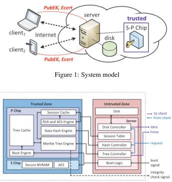
To build a trusted cloud storage system that efficiently guarantees integrity and freshness of cloud data, we attach a piece of trusted hardware to an untrusted server and adopt the S-P chip model as the trusted hardware; that is, the functionality of the trusted hardware is split into S and P chips. The P chip, which can be an FPGA board or an ASIC, has high computing power but only volatile memory,
server disk client1 client2 Internet PubEK, Ecert S-P Chip trusted PubEK, Ecert
Figure 1: System model
Trusted Zone Untrusted Zone
Disk
Session Table
Server
Merkle Tree Engine Tree Cache P Chip Tree Controller Hash Controller Boot Logic Boot Engine request Secure NVRAM S Chip data hmac boot signal Session Cache
RSA and AES Engine Data Hash Engine
integrity check signal Disk Controller to client from client AES
Figure 2: Design overview
while the S chip, which can be a smart card, has secure NVRAM but only constrained resources.
Figure1represents the system model. For simplicity, we make an assumption that a single-server system provides its clients with a block-oriented API to access a large virtual disk. The clients access the cloud storage service via the Internet; the untrusted server is connected to the disk and the trusted S-P chip pair.
To access/modify the cloud data, the clients send read/write re-quests, wait for the responses, and then check data integrity and freshness. The untrusted server schedules requests from the clients, handles disk I/O, and controls the communication between the P chip and S chip. The S-P chip pair shares a unique and secret HMAC key with each client, and thus essentially becomes an ex-tension of the clients. The S-P chip pair is trusted to update and store the system’s state, manage write access control, verify data integrity, and authenticate the responses sent to the client using the HMAC key. More specifically, the P chip performs all of the sen-sitive computations and stores the system’s state when the system is powered, and the S chip securely stores the system’s state across power cycles. This scheme simplifies the computation and verifica-tion that need to be done by clients in software-based soluverifica-tions, and abstracts away the design complexity and implementation details.
3.2
Threat Model
In our system model shown in Figure1, the cloud server is un-trusted: it may answer the clients’ read requests with stale or cor-rupted data, and it may pretend to be a client and overwrite the client’s data. The server may maliciously crash and disrupt the P chip’s supply power to drop the clients’ recent updates. The disk is vulnerable to attackers and hardware failures, so the data stored on the disk may not be correct. All connection channels within the system (including the communication between the S and P chips) are also untrusted. Any message traveling on the channels may be altered to an arbitrary or stale value. A client is trusted with the data he/she is authorized to access, but the client may try to modify the data outside the scope of his/her access privilege.
Table 1: Notation Notation Description
H(X) the hash value of X
{M}K the encryption of message M with the key K HMACK(M) the HMAC of message M with key K
MTXYN the message type indicating that a message issent from X to Y with sub-type N
This work allows clients to identify the correctness of the re-sponses sent from the server. If the received response is incorrect, the client will not accept it and will resend the original request or report the event to the system manager. Therefore, receiving an in-correct response can be considered as a missing response and can be treated as a denial-of-service attack, which falls out of the scope of this work.
3.3
Chain of Trust
The S chip and P chip are securely paired during manufactur-ing time and thus can be seen as a smanufactur-ingle TCB. The two chips share an endorsement key pair(PubEK,PrivEK) and a symmetric encryption key SK. The manufacturer, who can be seen as a CA, signs PubEK and produces the endorsement certificate (ECert) to promise that PrivEK is only known to the S-P pair. Our S-P pairing procedure is similar to that described in [9]. We use the S-P chip pair as the root of trust and establish the chain of trust, allowing clients to trust the computation and verification performed by our storage system.
When a client connects to the cloud server, ECert (and PubEK) is presented to the client for verification. If the verification is suc-cessful, which means PubEK can be trusted, the client can secretly share an HMAC key with the S-P chip pair by encrypting the HMAC key under PubEK. The S-P chip pair can then use the HMAC key to authenticate the response messages sent to the client.
In this work, we also provide a single-chip solution where the S chip and P chip are integrated into an ASIC. This chip can be viewed as a smart card running at a higher frequency with addi-tional logic for data hashing. The detailed specification is described in Section6.3.2. In this solution, the communication between the S and P chips becomes on-chip and can be trusted, so the pair-ing scheme is no longer required. This spair-ingle chip also generates (PubEK,PrivEK) and SK at manufacturing time and follows the chain of trust model described above.
4.
DESIGN
Figure2represents our prototype system architecture, which con-sists of two parts: an untrusted server with an untrusted disk, and a trusted S-P chip pair. This section introduces our system’s char-acteristics and describes how we achieve the security and perfor-mance goals. The detailed hardware mechanisms are discussed in Section5. Table1lists the symbols used in our design concepts and protocols. More details about our exact protocol are provided in a separate technical report [37].
4.1
Memory Authentication
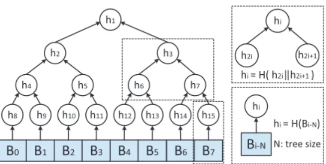
To verify the integrity and freshness of the disk data, we build a Merkle tree [27] on top of the disk (see Figure3). The hash function’s collision resistance property allows the Merkle tree root, which is also called the root hash, to represent the current disk state. The root hash is calculated and stored in the S-P chip pair, so it can be trusted against any corruption or replay attacks. The root hash is guaranteed to be always fresh, and leaf hashes are verified
B
0B
1B
2B
3B
4B
5B
6B
7 h1 h2 h3 h4 h5 h6 h7 h8 h9 h10 h11 h12 h13 h14 h15 hi = H(Bi-N) hi h2i h2i+1 hi = H( h2i h2i+1 )B
i-N hi N: tree sizeFigure 3: A Merkle tree example for a disk with 8 blocks
by the S-P chip pair to be consistent with the root hash and sent to the clients in the response messages, which are authenticated using HMACs. Therefore, a client can detect any data corruption or forking attack by verifying the received data against the received leaf hash. There is no need to communicate with other clients to check the data consistency.
To improve the efficiency of the Merkle tree authentication, we let the P chip cache some tree nodes. The caching concept is sim-ilar to what Gassend et al. proposed in [13]: once a tree node is authenticated and cached on-chip, it can be seen as a local tree root. While Gassend et al. use the secure processor’s L2 cache, which is on-chip and assumed to be trusted, to cache tree nodes, we cache the tree nodes on the P chip and let the untrusted server control the caching policy. This is because software has much higher flexibility to switch between different caching policies in order to match the data access patterns requested by various cloud-based applications. In our prototype system, the entire Merkle tree is stored on the untrusted server. The P chip caches tree nodes; its Merkle tree engine (see Figure2) updates the cached nodes to reflect write op-erations and verifies the tree nodes to authenticate read opop-erations.
The Merkle tree engine manages the cached nodes according to the commands sent from the server’s tree controller, which controls the caching policy. There are three cache management commands: (1) the LOAD command asks the tree engine to load a certain tree node and evict a cached node if necessary; (2) the VERIFY com-mand asks the tree engine to authenticate two child nodes against their parent node; (3) the UPDATE command asks the tree engine to calculate and update the tree nodes on a certain path from a leaf node to the root. These commands are sent from the untrusted server; therefore, the tree engine performs additional checks for each command to prevent integrity and freshness violations. If any verification step fails, the integrity check signal is raised to report the error to the system manager.
4.2
Message Authentication
We use the HMAC technique to create an authenticated channel over the untrusted connection between each client and the trusted S-P chip pair. Requests/responses are verified with HMACs to pre-vent message corruption or replay attacks. Each HMAC key should be only known to the client and the S-P chip pair.
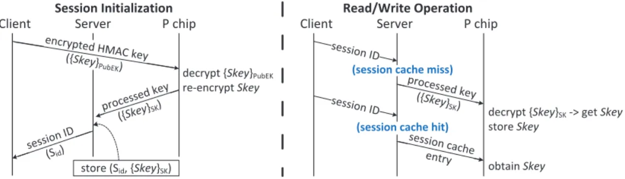
Figure4describes how we securely share the HMAC key be-tween a client and the S-P chip pair with minimal performance overhead even when the system serves multiple clients. The client and server communicate via a session-based protocol.
Each time a client connects to the server, the client first requests a session. Each session has a unique HMAC key, so an HMAC key is also called a session key (Skey). To share Skey with the S-P chip, the client encrypts Skey with PubEK and sends it along with the request for a new session. Then server assigns a new session ID
Client Server P chip
encrypted HMAC key ({Skey}PubEK)
processe d key ({Skey}SK
)
decrypt {Skey}PubEK
re-encrypt Skey
store (Sid, {Skey}SK) session
ID (Sid)
Client Server P chip
session ID
processed key ({Skey}SK)
Session Initialization Read/Write Operation
session ID
session cache entry
obtain Skey
(session cache miss)
(session cache hit)
decrypt {Skey}SK -> get Skey
store Skey
Figure 4: HMAC key management protocol
to the client and forwards the encrypted key ({Skey}PubEK) to the P chip. The P chip can decrypt{Skey}PubEKusing PrivEK, which is only known to the S-P chip pair. To eliminate the need for key transmission in future read/write operations, the P chip caches Skey. In addition, the P chip generates the processed key by re-encrypting Skeywith the symmetric key SK and stores it on the server, because symmetric key decryption is much faster than public key decryp-tion. During each read/write operation, the client sends the session ID with the request, and Skey can be obtained from the P chip’s cache or from the decryption of{Skey}SKstored on the server.
4.3
Write Access Control
We let the S-P chip pair manage write access control to ensure fresh writes and prevent unauthorized writes from the server and clients. No unauthorized user or malicious server can overwrite a block without being detected by the S-P chip pair or an authorized user. In addition, all writes are ensured to be fresh; that is, an old write from an authorized user cannot be replayed. Note that we do not focus on read access control in our system because a client can prevent unauthorized reads by encrypting the data locally, storing the encrypted data on the cloud, and sharing the read access key with authorized users without changing the system design.
To manage a situation where a data block has multiple authorized writers, we assume a coherence model in which each user should be aware of the latest update when requesting a write operation. Each set of blocks with the same authorized writers has a unique write access key (Wkey), which is only known to the authorized writers and the S-P chip pair. In addition, to protect data against re-play attacks, each block is associated with a revision number (Vid), which increases during each write operation, and each Merkle leaf node should reflect the change of the associated Wkey and Vid. In this way, any change of Wkey and Vid in any data block would change the root hash, and therefore cannot be hidden by the un-trusted server. In the following paragraphs, we describe this write access control scheme in more detail.
For each block, in addition to the data itself, the server also stores the block’s write access information, which consists of the hash of the write key (H(Wkey)) and the revision number (Vid). To guaran-tee that the write access information stored on the server is correct and fresh, we slightly modify the original Merkle tree by changing the function used to compute each leaf node to reflect any change of the write access information. The new formula is shown in Equa-tion1, where H refers to the cryptographic hash function used in the Merkle tree. It is similar to adding an additional layer under the bottom of the Merkle tree. Each leaf node in the original Merkle tree now has three children: the original leaf hash (H(data)), the hash of the write key (H(Wkey)), and the revision number (Vid). We refer the children of each leaf node to leafarg.
leaf = H(H(data)||Vid||H(Wkey)) = H(leafarg) (1) Figure5describes how the P chip manages the write access con-trol. When a client reads a block, the server sends the latest revi-sion number (Vid) along with the response. On the next write to the same block, the client encrypts the write key (Wkey) and the new revision number (Vid+1) under Skey, then sends the encrypted message as well as the hash of the new write key (H(Wkey∗)) along with the write request. Wkey∗ is different from Wkey only if the client wants to change the access information, e.g., revoking a cer-tain user’s write access. The P chip first authenticates the access information stored on the server by checking it against the verified leaf node. Then, the P chip checks the client’s access information against what is stored on the server. If the write keys are not consis-tent, the P chip rejects the write request directly. If the client’s new revision number is not larger than the one stored on the server by 1, the P chip sends the client the correct revision number (the one stored on the server) to inform the client that some other authorized users have already updated the block and the client’s write request needs to be re-issued. If verification is successful, the P chip gener-ates the new leaf value to reflect the change of the access informa-tion and performs tree updates. In this scheme, only the users with correct Wkey can increase Vidand send a valid{Wkey||Vid+ 1}Skey to perform updates, and H(Wkey) and Vidstored on the server are guaranteed to be correct and fresh under the Merkle tree protection. When the disk is initially empty, the P chip does not check the access of the first write to each data block. After the first write, the write key has been established, and the P chip starts to check subsequent writes following the write access control scheme men-tioned above. In a real cloud storage case, when a client requests a chunk of data blocks, the server can first establish a write key for these data blocks and shares the write key with the client. Then, the client can overwrite the write key to prevent the server from modifying the data.
4.4
State Protection against Power Loss
While the S chip is responsible for storing the root hash, which is the system’s state, across power cycles, the P chip computes and up-dates the root hash in its volatile memory (the tree cache), in which the data stored is vulnerable to power loss. To prevent the server from maliciously or accidentally interrupting the P chip’s supply power and losing the latest system state, the P chip should keep sending the latest root hash to the S chip and delay the write re-sponses to be sent to the clients until the latest root hash is success-fully stored on the S chip. When a client receives a write response, the system guarantees that the system state stored in the NVRAM can reflect the current write operation or the client/S-P chip pair can
Client Server P chip read
H(Wkey*), data*, {Wkey║Vid+1}
Skey leafarg , leaf, H(Wkey*), H(data *) {Wkey║Vid+1} Skey Vid+1, leaf* allow update(leaf*)
decrypt {Wkey║Vid+1}Skey verify leaf, leafarg check Wkey, Vid+1
leafarg = H(data) ║ Vid ║H(Wkey), leaf = H(leafarg )
leafarg* = H(data*)║ Vid+1║H(Wkey*) , leaf* = H(leafarg*)
issue read issue write Vid , HMACSK(Vid) Vid
Figure 5: Write access control example
Client Server P chip
write1 S chip update1 store HMACw1 write2 update2 store HMACw2 storeRoot() s, HMACSK(MTPS1║s║n) via Server HMACSK(MTSP1║s║n) HMACw1, HMACw2 read1 write4 certifyRead 1 store HMACr1 update4 store HMACw4 read5 certifyRead5 store s
writei : wrtie block i readi : read block i
HMACwi: response for writei HMACri : response for readi
s: root hash n: nonce
MTXYN: message type HMACr5
data5
n
Figure 6: Root hash storage protocol
detect the inconsistency. Considering that the S chip has long write times (around 1 ms/byte for smart cards [30]), in order to maintain high throughput, the P chip handles the clients’ new requests but stores the responses in an on-chip buffer while waiting for the S chip’s acknowledgment of successfully saving the root hash.
Figure6illustrates our root hash storage protocol. After a Merkle tree update, the P chip generates an HMAC to authenticate the write operation, stores the HMAC in the on-chip buffer instead of send-ing it to the client immediately. When receivsend-ing the server’s store-Root() request, the S chip sends a random nonce (n) to the P chip, and the P chip sends the latest root hash (s) to the S chip. While waiting for the S chip’s acknowledgment, the P chip keeps handling clients’ requests and generating responses (HMACwiand HMACri). The P chip stores the responses that are used to authenticate write operations or read operations that access the same blocks written by buffered write operations. The P chip releases the responses only if it receives a valid acknowledgment from the S chip indicating that the corresponding root hash has been successfully stored.
R/W Sid Bid N {Wkey║Vid}Skey H(data)
W 36 4 321f… ed20… 53c7… R 15 4 4b1b…
W 11 6 ac03… c700… ed27… W 21 5 aef3… ef2b… be42… W 21 2 345f… 2516… 21a0… R 53 2 a215... W 53 7 f213... 87c1… 8b32… W 12 1 ae2b… 781b… 52cf… … … …… …… …… …… …… D0 D1 D2 D3 D4 D5 D6 D7 (i-1)th snapshot Request Log Di= datai Normal Storage (Disk)
Storage for Recovery (Disk) RAM
Li=leafarg_i=H(datai)║Vid_i║ H(Wkeyi) L0 L1 L2 L3 L4 L5 L6 L7 S Chip i th snapshot ith root (i-1)thɦ i th root hash Inconsist ent with Disk Crash! NVRAM
Figure 7: Crash-recovery mechanism
In the two-chip prototype system, communication between the S chip and P chip is via server and thus untrusted. To securely store the latest root hash on the S chip, after the P chip receives the nonce nfrom the S chip, it sends out HMACSK(MTPS1||s||n) along with the root hash s, and the S chip uses HMACSK(MTSP1||s||n) as the acknowledgment, where MTPS1and MTSP1are message types used to distinguish the HMACs sent by the P chip and by the S chip so that the server cannot maliciously acknowledge the P chip. In a single-chip solution, the communication between the S and P chips becomes trusted, and hence the HMACs for the root hash storage protocol are no longer needed.
4.5
Crash-Recovery Mechanism
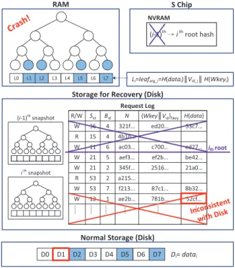
The crash-recovery mechanism ensures that even if the server accidentally/maliciously crashes, the disk data can be recovered to the state that is consistent with the root hash stored on the S chip.
There are two possible scenarios in which the disk state after the server re-boots is not consistent with the root hash stored on the S chip. One happens when the server crashes after the root hash is stored on the S chip but the data has not yet been stored on the disk. The other one happens when the server crashes after the data is stored on the disk but the corresponding root hash has not yet been stored on the S chip. To prevent the first scenario, the server should first flush the data into disk before it passes the root hash to the S chip, eliminating the possibility that the root hash is newer than the disk state. To recover from the second scenario, we keep a request log on the disk where we save a snapshot of the Merkle tree leaf arguments (H(Wkey),Vid,H(data) for each block).
Figure7shows how the recovery scheme works. When the server sends out a storeRoot() command and obtains the latest root hash (ithroot hash) from the P chip, it flushes data into the disk, takes a snapshot of the current Merkle tree leaf arguments (ithsnapshot) and stores it on the disk. After the data and snapshot are stored on the disk, the server sends the root hash to the S chip and continues
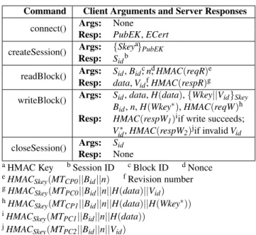
Table 2: API between client and server
Command Client Arguments and Server Responses
connect() Args: None
Resp: PubEK, ECert createSession() Args: {Skeya}PubEK
Resp: Sidb
readBlock() Args: Sid, Bidc, nd, HMAC(reqR)e Resp: data, Vidf, HMAC(respR)g
writeBlock() Args: Sid, data, H(data), {Wkey||Vid}Skey Bid, n, H(Wkey∗), HMAC(reqW)h Resp: HMAC(respW1)iif write succeeds;
Vid∗, HMAC(respW2)jif invalid Vid closeSession() Args: Sid
Resp: None
aHMAC Key bSession ID cBlock ID dNonce
eHMAC
Skey(MTCP0||Bid||n) fRevision number
gHMAC Skey(MTPC0||Bid||n||H(data)||Vid) hHMAC Skey(MTCP1||Bid||n||H(data)||H(Wkey∗)) iHMAC Skey(MTPC1||Bid||n||H(data)) jHMAC Skey(MTPC2||Bid||n||Vid)
to handle clients’ new requests. The Merkle tree and access infor-mation stored in the RAM are updated by new write requests. The request log buffers all the requests whose responses are buffered by the P chip without storing any actual write data. Note that we also keep the previous snapshot ((i − 1)thsnapshot) on disk so that the system is able to recover from a crash that happens after the server sends the root hash but before the root hash is successfully stored. When the server receives the S chip’s acknowledgment saying that the ithroot hash is successfully stored, it clears all the requests that are not newer than the ithroot hash from the request log.
When the server reboots after crashes, it first re-loads the snap-shots, re-builds the two Merkle trees, and chooses the one that is consistent with the S chip’s root hash. Then, the server re-performs the requests in the request log until the root hash is consistent with the disk state. If the untrusted server fails to correctly perform this crash-recovery mechanism, the clients will be able to detect the in-consistency between the disk state and the state stored on the S chip when they issuing read requests. We assume that each write of a data block is atomic; that is, the file system guarantees that writing the whole amount of data within one data block is not interrupted.
4.6
Trusted Storage Protocol
Table2shows the API between each client and the server. In the following we describe how the components in our system work together to provide a trusted storage service.
When the cloud server boots, the server’s boot logic re-pairs the S chip and P chip and executes the recovery procedure if the server re-boots from a crash. When a client requests a new session, the server assigns a new session ID (Sid) to the client and stores the client’s HMAC key (Skey) as described in Section4.2. After the session is created, the client uses Sidto communicate with the stor-age system, sending read/write requests to access/modify the data. For a read request, the server reads disk data and asks the P chip to verify the Merkle tree nodes and to generate an HMAC for au-thentication. As described in Section4.4, the P chip buffers the HMAC if the client tries to access the data that is not yet reflected by the S chip’s root hash. For a write request, the P chip checks the client’s write access and only allows authorized users with a correct revision number to update the Merkle tree (see Section4.3). The
Table 3: P chip implementation summary
Modules FFs LUTs Block RAM/FIFO
Data Hash Engine 4408 5597 0 kB
Merkle Tree Engine 4823 9731 2952 kB
Ethernet Modules 1130 1228 144 kB
Total 10361 16556 3096 kB
server writes the data into the disk and asks the P chip to send the latest root hash to the S chip. The P chip buffers the HMAC for the write operation until the root hash is successfully stored on the S chip. At the same time, the server stores the required information on the disk as described in Section4.5so that the system is able to recover from crashes.
5.
IMPLEMENTATION
In this section, we present the implementation details of our pro-totype system. To evaluate the system performance and overhead introduced by security mechanisms, we implement the client and server on Linux platforms. The client and server communicate over TCP, and both of them are running at user-level. The P chip is im-plemented on an FPGA board, which connects to the server using Gigabit Ethernet. To increase the implementation efficiency while maintaining the evaluation accuracy, the timing and functionality of the S chip are modeled by the server. For convenience, we refer to the implemented system as ABS (authenticated block storage), which consists of an ABS-server and an ABS-client.
5.1
P Chip Implementation
We implemented the P chip on a Xilinx Virtex-5 FPGA, using Gigabit Ethernet to connect with the server. Inside the P chip (see Figure2), the AES engine, data hash engine, and Merkle tree en-gine can be executed in parallel while sharing a single Ethernet I/O. The implementation of the boot engine and the session cache can be safely omitted and modeled by the server because they only in-troduce constant overhead per reboot or per session.
The AES engine [3] is mainly designed for symmetric decryption of the client’s write access information used in our write access con-trol protocol (see Section4.3), which requires one symmetric de-cryption and two hash calculations to be performed on the P chip. The AES engine can also be reused for the boot process and the HMAC key decryption. The data hash engine is used to verify the integrity of data sent from a client by checking the computed hash against the hash sent from the client. We implemented a 4-stage pipelined SHA-1 engine ([34]) for performance reasons. This hash engine can also be replaced by a software hash function without degrading the security level when hardware resources are limited. If the server mis-computes the hash and allows the wrong data to be stored on disk, the inconsistency can be detected by the client on the next read to the same block. The Merkle tree engine uses an-other pipelined hash engine to perform hash verifications and tree updates. The tree engine can pipeline multiple tree updates on dif-ferent update paths (while the update steps on the same path need to be serialized) and reduce the number of hash operations by merg-ing the hash operation performed by siblmerg-ing nodes. Table3shows a summary of the resources used by the P chip.
5.2
S Chip Implementation
The S chip has fixed and limited functionality and thus has little space for performance optimization. Therefore, for simplicity, in-stead of implementing the S chip on a smartcard, we modeled its functionality and timing on the server. The speed of the S chip can
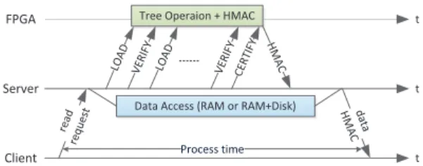
FPGA Server Client read req ue
st Data Access (RAM or RAM+Disk)
Tree Operaion + HMAC
LO AD VE RIFY LO AD VE RIF Y HMA C dat a HMA C Process time t t t CE RTIF Y
Figure 8: Timeline of a read operation
affect the system latency overhead because of the root hash storage protocol (see Section4.4), which requires the P chip to buffer the responses of the write operations and related read operations until the latest root hash is stored on the S chip. The latency overhead depends on the issuing rate of the server’s storeRoot() requests and the round-trip time, which consists of the time the server spends on flushing the data to disk, the time the S chip spends on stor-ing the 20-byte root hash (around 20 ms), checkstor-ing and generatstor-ing HMACs (around 2 ms if using a 32-bit RISC CPU or less time if using a SHA-1 hardware engine). To evaluate the root hash stor-age protocol, the modeled S chip sends back the acknowledgment 22 ms after it receives the latest root hash.
5.3
Server Implementation
We built the server on Linux. As shown in Figure2, the data con-troller handles disk accesses; the hash concon-troller and tree concon-troller send commands via the Ethernet controller to control the compu-tation on the P chip. The server schedules operations following the trusted storage procedure described in Section4.6. To achieve parallel execution, we put the data controller on another thread.
Figure8shows the timeline of a read operation. When receiving a read request, the server reads the data from the disk or the buffer cache. Meanwhile, the server sends the tree operation commands to the FPGA and asks the FPGA to generate an HMAC for authen-tication. After the server receives the data and HMAC, the server sends them to the client and starts to handle the next request.
When handling a write operation, the server checks the integrity of data sent from the client by re-computing the hash of data and checking against the client’s data hash before the server writes the data to disk. To minimize the latency, we perform speculative writes: the server writes the data into the buffer cache in parallel with the hash engine operation. If the verification fails, the data in the buffer cache should be discarded. The operating system should be modified so that it only writes correct data blocks to the disk.
Figure9shows the timeline of a write operation. When receiv-ing a write request, the server sends the client’s data and encrypted write access information ({Wkey||Vid}Skey) to the FPGA; in the meantime, the server writes the data into the buffer cache. After the data and write access information are verified, the server sends tree cache commands to the FPGA and data to the disk. The P chip generates and buffers the write response (HMAC) until receiving the root hash storage acknowledgment from the S chip. The server schedules the root hash storage protocol by sending out storeRoot() requests and forwarding the root hash from the P chip to the S chip after the data and Merkle tree snapshot are stored on the disk. Since the disk write controlled by the operating system can be done in the background, the next request can be handled once the server finishes writing the data to the buffer cache and the FPGA finishes generating the HMAC. Therefore, in general, the disk write time (as well as the S chip write time) does not affect the system through-put if the P chip’s response buffer is large enough.
Client
Application ABS-Client (NBD Server) NBD req/resp handler Data Cache Security Checker ABS req/resp handler N BD C li e n t Filesystem (ext2) ABS-Server
Figure 10: The client model
The throughput and latency of the buffer cache can be seen as the optimal performance our system can achieve, since all data sent from the server or from the disk must pass through the buffer cache. If there is a perfect caching scheme and a sufficient number of hard disks, then the disk read time will be close to the RAM access time, and disk write time will not affect the system throughput but only introduce a constant latency. In Section6.1, we measure the opti-mal system throughput by measuring the data access time to/from the buffer cache when running micro-benchmarks. Instead of mod-ifying the operating system, we store all test data in a RAM buffer, which mimics the buffer cache with a 100% hit rate. In Section6.2, we evaluate our system using a real disk and analyze the disk im-pact on system latency when running file system benchmarks.
5.4
Client Implementation
To allow end-to-end evaluation that takes the network latency and throughput into account (see Section 6.2), we implemented a client model as shown in Figure10. User applications are run-ning on top of the ext2 filesystem that is mounted on a network block device (NBD). When a user-program accesses the filesystem, the NBD client forwards the request to the ABS-client, which pro-cesses and sends the request to ABS-server, where the data physi-cally resides.
The communication between the ABS-client and ABS-server fol-lows the client-server API described in Table2. To amortize the overhead introduced by security mechanisms, ABS prefers block sizes that are larger than the block size of a typical filesystem. For example, in our evaluation, we fix the block size of ABS as 1 MB, while ext2 uses 4 KB blocks. To handle requests in different block sizes, the ABS-client merges continuous reads and writes to elim-inate redundant requests to the ABS-server and adds read-modify-writes to deal with partial read-modify-writes. To further optimize the perfor-mance of large block sizes, we keep a 16 MB local write-through cache in the ABS-client and allow partial write data with the hash of the whole block to be sent to the server.
6.
EVALUATION
This section evaluates the throughput and latency of our proto-type system. The performance overhead introduced by providing integrity and freshness guarantees is analyzed. We also provide sug-gestions on hardware requirements for different storage providers.
To conduct our experiments, the ABS-server program runs on an Intel Core i7-980X 3.33 GHz processor with 6 cores and 12 GB of DDR3-1333 RAM. The ABS-server computer connects with a Xil-inx Virtex-5 XC5VLX110T FPGA board and an ABS-client com-puter, which is an Intel Core i7-920X 2.67 GHz 4 core processor, via Gigabit Ethernet. The client-server connection can be config-ured to add additional latency and impose bandwidth limits.
In our experiments, we fix the disk size as 1 TB and block size as 1 MB, which is close to the block sizes used in current cloud storage system. For example, Dropbox uses 4 MB blocks, and the Google
Write Data to Disk FPGA Client wri te req uest Write to RAM
Decrypt {Wkey║Vid}Skey and verify
has h data stream ofdat a Tree UPDATE LO AD VERIF Y LO AD VERIF Y UP DA TE root HMA C Process time t t t Server (with modeled S chip) Hash Data {Wke y║V id} Skey leaf arg Tree Operaion (VERIFY leaf) verify leafarg sto reR oot( ) AC K (modeled S chip) HMA C Tree Snapshot to Disk 22ms
Figure 9: Timeline of a write operation
Table 4: Micro-benchmarks
Benchmark Type Description
read/write only cont sequentially read/write 2 GB read/write only period sequentially read/write the same256 MB space 8 times read only random randomly read from 2 GB write only random randomly write from 2 GB random read write randomly read or write from 2 GB(read probability = 0.8)
Table 5: Detailed timing analysis (in ms)
Benchmark AccessData Hash HMACTree +
read only random
Baseline 4.01E-1 0 1.69E-3
ABS-SOFT 3.93E-1 0 2.02E-2
ABS-HARD 3.97E-1 0 2.04E-2
write only random
Baseline 1.76E-1 2.29 2.40E-3
ABS-SOFT 1.74E-1 2.33 3.72E-2
ABS-HARD 1.69E-1 9.51 3.69E-2
File System uses 64 MB chunks [14]. For a storage provider, the best choice of the block size depends on its clients’ access patterns.
6.1
Micro-Benchmarks
To analyze the overhead introduced by the memory authentica-tion scheme and the maximum throughput that the ABS-server can provide, we built another system assuming the server is trusted and refer to it as Baseline. Baseline-server is trusted to generate HMACs and perform all the authentication and permission checks. We run micro-benchmarks (listed in Table4) on the Baseline-server and ABS-server and then compare their performance. To measure the throughput upper bound, two servers were simplified by remov-ing the real disk as well as the root hash storage protocol and crash-recovery mechanism that are affected by the S chip and the disk write time. As mentioned in Section5.3, we store all the test data in the RAM buffer and measure the data access time to/from the RAM buffer. Both the RAM buffer size and the working set size are set as 2 GB.
We compare the performance of the Baseline and ABS in terms of average processing time, which is measured from when the server dequeues a request until when the server finishes processing it. In Table4, in addition to the random accesses, the continuous data accesses simulate backup applications for a single client, while the repeated data accesses simulate group collaboration on the same chunk of data.
Table 6: ABS performance summary
Configuration ABS-SOFT ABS-HARD
Randomly Write Throughput 411 MB/s 104 MB/s Latency 2.4 ms 12.3 ms Randomly Read Throughput 2.4 GB/s Latency 0.4 ms 0 1 2 3 4 5 6 7 8 9 10 read only cont read only period read only random write only cont write only period write only random random read write A v er ag e Pr ocessi ng Ti m e (msec)
Baseline ABS-SOFT ABS-HARD
Figure 11: Average processing time comparisona a2048 operations on 1 MB data blocks with tree cache size = 214
Figure11 shows the processing time comparison between the Baseline and ABS with two configurations: using a hardware data hash engine (ABS-HARD) or a software hash (ABS-SOFT). The three schemes have the same performance when handling reads, while ABS-HARD is four times slower when handling writes. To understand which component slows down the system, we performed detailed timing analysis as shown in Table5. When handling reads, the processing time is equal to the data access time. The latency of Merkle tree and HMAC operations is completely hidden because they are fast enough and can be executed in parallel with data ac-cess. When handling writes, the hash operation dominates the pro-cessing time and introduces large overhead in ABS-HARD because the throughput and latency of the hash engine are limited by the Ethernet connection, which has the throughput of 125 MB/s.
Table6shows the performance of ABS-SOFT and ABS-HARD. The hash engine in our prototype hardware has lower throughput and higher latency due to the limitation of Ethernet I/O, and it runs at a much lower clock frequency (125 MHz, which is also limited by the Ethernet speed) compared to that of the software hash function (3.33 GHz). However, in a real storage system, these limitations can be easily removed by using an ASIC as the P chip. The clock fre-quency can be increased to 500 MHz or 1 GHz, and a faster data bus, such as PCI Express x16, can be used. Moreover, it is cheaper and more energy-efficient to have multiple hash engines in hardware to achieve throughput higher than that of software hash function.
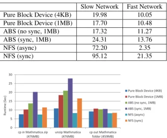
Table 7: Modified Andrew Benchmark (in sec) Slow Network Fast Network
Pure Block Device (4KB) 19.98 10.05
Pure Block Device (1MB) 17.70 10.48
ABS (no sync, 1MB) 17.32 11.27
ABS (sync, 1MB) 24.31 13.76 NFS (async) 72.20 2.35 NFS (sync) 95.12 21.35 0 5 10 15 20 25 30 cp in Mathmatica.zip (476MB) unzip Mathmatica (476MB) cp out Mathmatica folder (459MB) R u n ti me (Sec )
Pure Block Device (4KB) Pure Block Device (1MB) ABS (no sync, 1MB) ABS (sync, 1MB) NFS (async) NFS (sync)
(a) Fast network with 0.2ms latency and 1Gbit/s bandwidth
0 20 40 60 80 100 120 140 160 180 200 cp in Mathmatica.zip (476MB) unzip Mathmatica (476MB) cp out Mathmatica folder (459MB) Ru n ti me (Sec)
Pure Block Device (4KB) Pure Block Device (1MB) ABS (no sync, 1MB) ABS (sync, 1MB) NFS (async) NFS (sync)
(b) Slow network with 30.2ms latency and 100Mbit/s bandwidth Figure 12: Runtime comparison on the Mathematica benchmark
6.2
File System Benchmarks
In addition to micro-benchmarks, which are used to measure the maximum system throughput and analyze the overhead intro-duced by the security checks at the server side, we performed end-to-end evaluation that takes client side overhead and network la-tency/bandwidth into account. During our end-to-end evaluation, all security protocols are active and implemented as described in detail in Section4and5. A real disk is used to analyze the impact of disk access time on the full system latency, and the S chip is simulated in software with a modeled response time.
We focus on two kinds of practical workloads: (1) copying and unzipping an Mathematica 6.0 distribution, which represent read-ing and writread-ing large files; (2) the Modified Andrew Benchmark (MAB) [28], which emulates typical user behavior. We ran two benchmarks on two network models, representing different scenar-ios when the authenticated storage server can be used. First, we ran benchmarks on the client-server network without imposing any latency or bandwidth limitations. The measured latency and band-width are 0.2 ms round-trip and 986 Mbit/s. We refer to this net-work as the fast netnet-work, which models the situation where both the client (which can be an application server) and the ABS-server are inside the data center. In addition to the fast network, we use tc (traffic control) to impose 30 ms round-trip delay and 100 Mbit/s bandwidth limitation to the network. The resulted net-work has measured 30.5 ms latency and 92 Mbit/s bandwidth, and it is referred as the slow network. The slow network setting models
Table 8: Hardware requirements
Demand Focused Performance Budget
Connection PCIe x16(P)/USB(S) USB
Hash Engine 8 + 1 (Merkle) 0 + 1 (Merkle)
Tree Cache large none
Response Buffer 2 KB 300 B
Table 9: Estimated performance
Demand focused Performance Budget
Randomly Write Throughput 2.4 GB/s 377 MB/s
Latency 12.3+32 ms 2.7+32 ms
Randomly Read Throughput 2.4 GB/s
Latency 0.4 ms
# HDDs supported 24 4
the situation where the ABS-server is in a remote data center, and the client is connecting over the Internet, from a corporate network or a fast home network (like Google Fiber).
Figure12and Table7show how ABS (which is ABS-SOFT) per-forms compared to a pure block device. To analyze the overhead of the crash-recovery mechanism, we include 2 ABS configurations: ABS (no sync, 1 MB) buffers responses every 22 ms, which is the modeled S chip write time; ABS (sync, 1 MB) forces data synchro-nization to the disk before it sends the root hash to the S chip. In Mathematica benchmarks (see Figure12), benchmark cp-in writes a large zip file into the filesystem; unzip unzips the file inside the filesystem; cp-out copies the entire folder to somewhere outside the filesystem, resulting in pure reads. Compared with the pure block device, which does not include any security checks, with the same block size (1 MB), ABS has the same read performance. The av-erage overhead is reduced from 40% to 10% when switching from the fast network to the slow network, because the overhead intro-duced in write operations (especially due to data synchronization) is mostly hidden by the long network latency.
We also ran benchmarks on a pure block device with 4KB block size to show how the choice of block sizes affects system perfor-mance. The system with the small block size performs well on the fast network but has much worse performance on the slow network when reading files. This is because the performance of reads is di-rectly affected by the long network latency, and the system with the large block size takes advantage of spatial locality by caching a few blocks locally.
In Figure12and Table 7, we also compared the ABS perfor-mance with two NFS configurations: NFS (async) and NFS (sync), where NFS (sync) forces data synchronization before the server sends back responses. NFS manages data at the file level; therefore, it has the best performance when handling few large files (Mathe-matica benchmarks). When handling many small files (MAB), NFS performs worse, especially on the slow network, because per file overheads dominate the execution time.
6.3
Suggestions on Hardware Requirements
Based on the micro-benchmark results of our prototype system, we provide two different hardware suggestions to cloud storage providers with different needs. We list the different hardware re-quirements for performance-focused and budget-focused storage providers in Table 8, and the estimated performance is listed in Table9. The estimated performance is derived from our experi-ment settings and micro-benchmark results. 32 ms additional write latency is modeled by the combination of disk write time and the
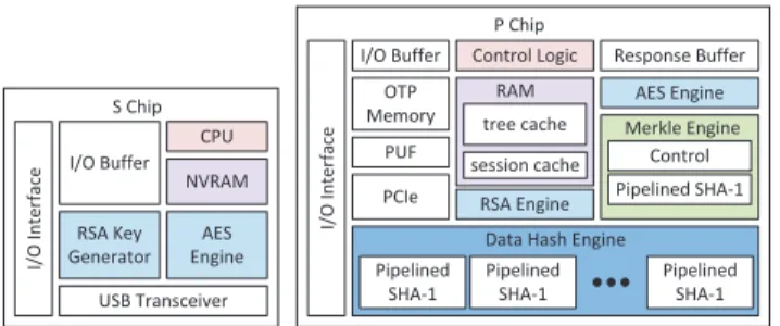
NVRAM S Chip I/O Buffer CPU RSA Key Generator I/ O Interface AES Engine RSA Engine AES Engine I/ O Interface P Chip I/O Buffer Control Logic
OTP Memory Pipelined SHA-1 PUF USB Transceiver RAM tree cache session cache Response Buffer Pipelined SHA-1 Control PCIe Merkle Engine
Data Hash Engine Pipelined
SHA-1
Pipelined SHA-1
Figure 13: Performance-focused (two-chip) solution
NVRAM I/O Buffer CPU RSA Key Generator I/
O Interface RSA Engine
USB Transceiver Response Buffer Un-pipelined SHA-1 Control Merkle Engine RAM session cache AES Engine
Figure 14: Budget-focused (single-chip) solution
S chip write time, which are introduced by the root hash storage protocol and the crash-recovery mechanism.
6.3.1
Performance-focused Solution
If a storage provider focuses on performance, our system can achieve a throughput as high as its RAM throughput, which is 2.4 GB/s, using multiple hardware data hash engines and a fast data bus. The throughput of a pipelined hash engine, 330 MB/s, is mea-sured using a mimic fast data bus which has 4× higher throughput than the Gigabit Ethernet. The higher throughput is modeled by only sending a quarter of each 1 MB block to the FPGA and ex-panding it at the FPGA side. To achieve 2.4 GB/s throughput of data hashing, we need 8 pipelined hash engines and a PCI Express x16 link, which supports up to 4.0 GB/s. Figure13shows the func-tional units of a S-P chip pair required by a performance-focused storage provider. A typical solution is an ASIC paired with a smart card chip. If the P chip’s computation logic runs at a clock fre-quency higher than 125 MHz, which is easy for an ASIC to achieve, the system latency and the number of hash engines required can be further reduced. For example, for an ASIC running at 500 MHz, only 2 data hash engines are required and the system latency can be lower than 3+32 ms. In addition, to maintain high throughput un-der the root hash storage protocol and crash-recovery mechanism, the P chip require a larger on-chip buffer to buffer write responses.
6.3.2
Budget-focused Solution
If a storage provider has limited resources, a solution with a soft-ware hash function and without a tree cache can be chosen to re-duce the cost while maintaining the system’s throughput around 400 MB/s for write requests and 2.4 GB/s for read requests (shown in Table9). We have simulated ABS-SOFT without a tree cache and observed that although the latency of tree operations was ten times larger, there was no significant overhead in the system latency. This is because the latency of tree operations is much smaller than that of other components.
In a budget-focused design, many functional units and on-chip storage are removed. Therefore, we can combine the functionality of the original two chip solution and build a single chip as shown in Figure14. This single chip can be imagined as a typical smart card chip running at around 125 MHz with an additional hardware hash
engine as well as some control logic and a on-chip buffer. In addi-tion, the on-chip communication is trusted, so the HMACs between the original two chips are no longer needed, which makes updating the root hash in the NVRAM easier. Under today’s NVRAM pro-cess, this single chip design is feasible in terms of chip area and speed. Therefore, this represents a cheap solution for trusted cloud storage, and yet is significantly more efficient than, for example, the solution of [36].
However, the maximum frequency of this single chip is limited by the NVRAM fabrication process. It is difficult for any logic on chip to run at a frequency higher than 1 GHz under today’s NVRAM process, and therefore PCI Express cannot be supported. Given limited frequency, the maximum system system throughput is limited by the communication throughput. For example, the hard-ware hash engine with 1 Gbps communication throughput limits the system throughput to 125 MB/s, no matter how many hash engines we have. This is also why we adopt software hashing, which has a limited throughput as 377 MB/s, in the single chip solution. On the other hand, the two-chip solution can break this frequency limit and achieve higher throughput as we provide in the performance-focused solution.
7.
CONCLUSION
In this work, we provide a detailed design and implementation of an authenticated storage system that efficiently ensures data in-tegrity and freshness by attaching a trusted pair of chips to an un-trusted server. We propose a write access control scheme to prevent unauthorized/replayed writes and introduce a crash-recovery mech-anism to protect our system from crashes. With micro-benchmarks, we show that even with limited resources the system can achieve 2.4 GB/s (as high as the server’s RAM throughput) for handling reads and 377 MB/s for handling writes using a single chip that is not appreciably more expensive than current smart card chips. If more hardware resources are available, the throughput for handling write requests can be increased to 2.4 GB/s. Our end-to-end evalu-ation on file system benchmarks also demonstrates that the proto-type system introduces little overhead—around 10% when a client connects to our remote server over the Internet from a corporate network or a fast home network.
8.
ACKNOWLEDGEMENTS
We acknowledge the anonymous reviewers for their feedback and the support from Quanta Corporation.
9.
REFERENCES
[1] Amazon. Amazon simple storage service. http://aws.amazon.com/s3/.
[2] Apple. iCloud. http://www.apple.com/icloud/. [3] P. Bulens, F. Standaert, J. Quisquater, P. Pellegrin, and
G. Rouvroy. Implementation of the AES-128 on Virtex-5 FPGAs. Progress in Cryptology–AFRICACRYPT, 2008. [4] C. Cachin. Integrity and consistency for untrusted services.
SOFSEM 2011: Theory and Practice of Computer Science, pages 1–14, 2011.
[5] C. Cachin and M. Geisler. Integrity protection for revision control. In Applied Cryptography and Network Security, 2009.
[6] C. Cachin, I. Keidar, and A. Shraer. Fail-aware untrusted storage. In IEEE/IFIP International Conference on Dependable Systems & Networks (DSN), 2009.