HAL Id: tel-01868248
https://tel.archives-ouvertes.fr/tel-01868248
Submitted on 5 Sep 2018HAL is a multi-disciplinary open access
archive for the deposit and dissemination of sci-entific research documents, whether they are pub-lished or not. The documents may come from teaching and research institutions in France or abroad, or from public or private research centers.
L’archive ouverte pluridisciplinaire HAL, est destinée au dépôt et à la diffusion de documents scientifiques de niveau recherche, publiés ou non, émanant des établissements d’enseignement et de recherche français ou étrangers, des laboratoires publics ou privés.
Modeling and Multi-Dimensional Analysis of a Proton
Exchange Membrane Fuel Cell
Daming Zhou
To cite this version:
Daming Zhou. Modeling and Multi-Dimensional Analysis of a Proton Exchange Membrane Fuel Cell. Electric power. Université Bourgogne Franche-Comté, 2017. English. �NNT : 2017UBFCA011�. �tel-01868248�
Univ. Bourgogne Franche-Comté, UTBM
École doctorale SPIM « Sciences pour l'ingénieur et microtechniques »
THESIS
Modeling and Multi-Dimensional Analysis of
A Proton Exchange Membrane Fuel Cell
By
Daming Zhou
A dissertation presented to the
Univ. Bourgogne Franche-Comt
é
, UTBM
in partial fulfillment of the
requirements for the degree of Doctor
28 september 2017
JURY MEMBERS:
M. Babak Nahid-Mobarakeh Institut National Polytechnique de Lorraine, Nancy M. Hubert Razik Université Claude Bernard Lyon 1, Lyon
M. Mahesh Krishnamurthy Illinois Institute of Technology, Chicago, USA M. Demba Diallo Université de Paris Sud, Paris
M. Abdellatif Miraoui Université de technologie de Belfort-Montbéliard, Belfort M. Damien Paire Université de technologie de Belfort-Montbéliard, Belfort M. Fei Gao Université de technologie de Belfort-Montbéliard, Belfort M. Alexandre Ravey Université de technologie de Belfort-Montbéliard, Belfort
ACKNOWLEDGMENTS
PUBLICATION LIST
INTRODUCTION ... 1
PREFACE ... 4
0.1 Introduction to Fuel Cell: What is Fuel Cell ... 4
0.2 Different types of Fuel Cells ... 4
0.2.1 Proton Exchange Membrane Fuel Cell (PEMFC) ... 5
0.2.2 Alkaline Fuel Cell (AFC) ... 5
0.2.3 Phosphoric Acid Fuel Cell (PAFC) ... 6
0.2.4 Molten Carbonate Fuel Cell (MCFC) ... 6
0.2.5 Solid Oxide Fuel Cell (SOFC) ... 6
0.2.6 Direct Methanol Fuel Cell (DMFC) ... 7
0.3 Why We Need A Proton Exchange Membrane Fuel Cell Model ... 7
0.3.1 Dynamic Behaviors ... 8
0.3.2 Spatial Distribution of Physical Quantities ... 9
0.3.3 Real-Time Applications ... 9
0.3.4 Degradation Prediction ... 9
0.4 Structure ... 10
0.5 Reference ... 11
Chapter I: Multi-Physic Proton Exchange Membrane Fuel Cell
Modeling ... 13
1.1 Literature Review ... 13
1.2 Multi-Physical PEMFC Model ... 15
1.2.1 Electrical Domain Modeling ... 16
1.2.2 Fluidic Domain Modeling ... 18
1.2.2.1 Cooling Channels ... 18
1.2.2.2 Gas Supply Channels ... 19
1.2.2.3 Gas Diffusion Layer (GDL) ... 20
1.2.2.4 Catalyst Layers ... 20
1.2.2.5 Dynamic Membrane Water Content... 21
1.2.3 Thermal Domain Modeling ... 23
1.3 Multi-Dimensional Modeling Considerations ... 25
1.3.1 Two-Dimensional Approach in Fluidic Model ... 27
1.3.1.2 Gas Diffusion Layer ... 30
1.3.1.3 Non-Uniform Control Volume Consideration ... 31
1.3.2 Two-Dimensional Approach in Electric Model ... 32
1.4 Conclusion ... 33
1.5 Reference ... 34
Chapter II: Experimental Validation and Coupling Analysis ... 38
2.1 Literature Review ... 38
2.2 Model Experimental Validation and Discussion ... 38
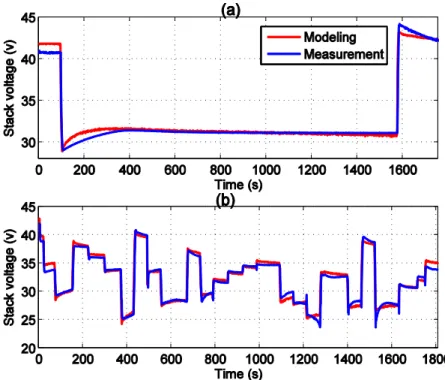
2.2.1 Experimental Validation of Dynamic Model ... 39
2.2.2 Dynamic Membrane Water Content Results and Discussions... 42
2.2.3 Effect of the Gas Supply Serpentine Channels and Discussions ... 43
2.3 2-D Model Simulation Results and Discussions ... 45
2.3.1 Model Grid Independence Analysis ... 45
2.3.2 Results and Discussions ... 46
2.4 Dynamic Phenomena Coupling Analysis ... 48
2.4.1 Expressions of Time Constant for Temperature and Membrane Water Contents 49 2.4.2 Analyses of Step Responses... 50
2.4.2.1 High Efficiency Operating Region ... 50
2.4.2.2 Rated power Operating Region ... 55
2.4.3 Coupling Analysis Using RGA Method ... 57
2.4.3.1 Relative Gain Array ... 57
2.4.3.2 Coupling Analysis of MIMO system (High Efficiency Operating Region) ... 59
2.4.3.3 Coupling Analysis of MIMO system (Rated Power Operating Region) ... 60
2.4.3.4 Coupling Analysis of Sub-System ... 60
2.5 Conclusion ... 62
2.5 Reference ... 63
Chapter III: PEMFC 2-D model numeric solver development for
Real-Time Control Implementation ... 65
3.1 Literature Review ... 66
3.2 Tridiagonal Matrix Algorithm for Real-Time Simulation ... 67
3.2.1 Tridiagonal Matrix Algorithm... 67
3.2.2 Modeling Hypotheses ... 69
3.2.3 Solve Reactant Gas Convection 2-D Model Using Tridiagonal Matrix Algorithm 70 3.2.4 Solve Reactant Gas Diffusion 2-D Model Using Tridiagonal Matrix Algorithm ... 72
3.4 Experimental Validation ... 76
3.4.1 Experimental Setup ... 76
3.4.2 Experimental Results ... 76
3.4.3 Real-Time Performance Comparison ... 77
3.4.3.1 Comparison with Newton’s Method ... 77
3.4.3.2 Comparison with Gaussian Elimination Method ... 78
3.5 Conclusion ... 79
3.6 Reference ... 80
Chapter IV: Degradation Prediction of Proton Exchange
Membrane Fuel Cell Stack ... 82
4.1 Literature Review ... 82
4.2 Degradation Prediction Based on Multi-physical Aging Model ... 85
4.2.1 Description of Aging phenomena... 85
4.2.1.1 Aging Parameter Membrane Resistance ... 86
4.2.1.2 Aging Parameter Exchange Current Density ... 87
4.2.1.3 Aging Parameter Gas Diffusion Coefficient ... 87
4.2.2 Estimation Method ... 87
4.2.2.1 State Space Model for Aging ... 88
4.2.2.2 Bayesian Estimation ... 89
4.2.2.3 Particle Filter Framework ... 90
4.2.3 Prediction Methodology Implement ... 91
4.2.3.1 Initialization of Aging Parameters ... 91
4.2.3.1.1 Initialization of Aging Parameter Ohmic Resistance ... 91
4.2.3.1.2 Initialization of Aging Parameter Exchange Current Density ... 91
4.2.3.1.3 Initialization of Aging Parameter Diffusion Coefficient ... 92
4.2.3.1.4 Genetic Algorithm ... 92
4.2.3.2 Prediction Method Design ... 94
4.2.4 Experimental Results and Discussions ... 96
4.2.4.1 Fitting Function Selection and Extrapolation Method ... 96
4.2.4.2 Experimental Validation: Long Learning Time ... 99
4.2.4.2.1 First Experiment: PEMFC Operation under 12A at 30°C ... 99
4.2.4.2.2 Second Experiment: PEMFC Operation under 30A at 35°C ... 100
4.2.4.2.3 Third Experiment: PEMFC Operation under 44A at 40°C ... 102
4.2.4.3 Experimental Validation: Short Learning Time ... 103
4.2.5 Conclusion ... 105
4.3.1 Model-Based Prediction Method ... 106
4.3.1.1 Initialization of Model-Based Approach ... 108
4.3.1.2 Training Phase of Model-Based Approach ... 109
4.3.1.3 Prediction Phase of Model-Based Approach ... 109
4.3.2 Data-Driven Prognostic Method ... 110
4.3.2.1 Non-linear Autoregressive Neural Network Model ... 110
4.3.2.2 Data-Driven Prognostic Method Implementation ... 111
4.3.3 Hybrid Prognostic Approaches ... 112
4.3.3.1 Moving Window Method ... 113
4.3.3.2 Weight Factors Calculation ... 115
4.3.4 Experimental Results and Discussion ... 116
4.3.4.1 First Case Study: Comparison of Hybrid Model and Single Model Methods ... 117
4.3.4.2 Second Case Study: Performance Evaluation ... 122
4.3.4.3 Third Case Study: Comparison of Hybrid Method with Other Methods ... 125
4.3.5 Conclusion ... 129
4.4 Reference ... 130
ACKNOWLEDGMENTS
This work was done while the author was with the FEMTO-ST (UMR CNRS 6174), Energy Department, Univ. Bourgogne Franche-Comte, UTBM and with the laboratory FCLAB in Belfort.
I would like to give the most sincere thanks to Prof. Dr. Fei Gao, who are respectively my supervisor in FEMTO-ST and FCLAB. I am grateful for his guidance and support in my research work and the preparation of this dissertation. I would also like to express my deepest appreciation to Prof. Dr. Alexandre Ravey and Prof. Dr. Abdellatif Miraoui, who are also my thesis supervisors, for their insightful discussion about this work and constructive comments on the dissertation.
I would also thank the colleagues in FEMTO-ST and FCLAB, for their working on the experiments corresponding to this work. Many thanks for the friends in Belfort.
I would like to give my sincere thanks to Miss MengLi Yin for her meticulous care and companionship in Strasbourg and Belfort.
Finally, I would also like to express my deepest gratitude to Miss JiaQi Shang, she gives me her companionship and a very precious journey in Meerane, Germany. This is a really unforgettable memory during my life. Thank you again for accompanying me, my forever dear Meerane, forever dear JiaQi, forever dear Jiji Zha.
PUBLICATION LIST
INTERNATIONAL JOURNALS
[1] D. Zhou, F. Gao, E. Breaz, A. Ravey, A. Miraoui, “Tridiagonal Matrix Algorithm for Real-Time Simulation of a 2-D PEM Fuel Cell Model,” IEEE Trans. Ind. Electron., Accepted and to be published;
[2] D. Zhou, F. Gao, E. Breaz, A. Ravey, A. Miraoui, K. Zhang, “Dynamic phenomena coupling analysis and modeling of proton exchange membrane fuel cells,” IEEE Trans. Energy Convers., Vol. 31, Issue.4, Pages 1399-1412, 2016;
[3] D. Zhou, K. Zhang, A. Ravey, F. Gao, A. Miraoui, “On-Line Estimation of Lithium Polymer Batteries State-of-Charge Using Particle Filter Based Data Fusion with Multi-Models Approach,” IEEE Trans. Ind. App., Vol. 52, Issue.3, Pages 2582-2595, 2016;
[4] D. Zhou, Y. Wu, F. Gao, E. Breaz, A. Ravey, A. Miraoui, “Degradation Prediction of PEM Fuel Cell Stack Based on Multi-Physical Aging Model with Particle Filter and Extrapolation Approach,” IEEE Trans. Ind. App., Vol. 53, Issue.4, Pages 4041-4052, 2017;
[5] D. Zhou, A. Al-Durra, F. Gao, A. Ravey, I. Matraji, M. G. Simões, “On-line energy management strategy of fuel cell hybrid electric vehicles based on data fusion approach,” Journal of Power Source, Vol. 366, Pages 278-291, 2017;
[6] D. Zhou, F. Gao, E. Breaz, A. Ravey, A. Miraoui, “Degradation Prediction of PEM Fuel Cell Using a Moving Window Based Hybrid Prognostic Approach,” Energy, Vol. 138, Pages 1175-1186, 2017;
[7] D. Zhou, A. Ravey, A. Al-Durra, F. Gao, “A Comparative Study of Extremum Seeking Methods Applied to Online Energy Management Strategy of Fuel Cell Hybrid Electric Vehicles,” Energy Conversion and Management, Vol. 151, Pages 778-790, 2017;
[8] D. Zhou, K. Zhang, A. Ravey, F. Gao, A. Miraoui, “Parameter Sensitivity Analysis for Fractional-Order Modeling of Lithium-Ion Batteries,” Energies, Vol. 9, Issue. 123, 2016;
[9] D. Zhou, A. Al-Durra, F. Gao, A. Ravey, I. Matraji, M. G. Simões, “On-line Energy Management Strategy of Fuel Cell Hybrid Electric Vehicles:An Fractional-Order Extremum Seeking Method,” IEEE Trans. Ind. Electron., First revision;
[10] D. Zhou, T. T. Nguyen, F. Gao, E. Breaz, S. Clénet, “Global Parameters Sensitivity Analysis and Development of a 2-D Model of PEM Fuel Cells,” Energy conversion and management, under review;
[11] D. Zhou, Y. Wu, F. Gao, E. Breaz, A. Ravey, A. Miraoui, “Degradation Development of a multi-physical 2-D model of PEM fuel cell for real-time control,” IEEE Trans. Ind. , under review;
[12] D. Zhao, M. Dou, D. Zhou, F. Gao, “Study of the modeling parameter effects on the polarization characteristics of the PEM fuel cell”, Int. J. Hydrogen Energy, Vol. 41, Issue 47, Pages 22316-22327, 2016;
INTERNATIONAL CONFERENCES
[13] D. Zhou, F. Gao, A. Ravey, A. Al-Durra, M. G. Simões, “On-line Energy Management Strategy of Fuel Cell Hybrid Electric Vehicles Based on Time Series Prediction,” IEEE Transportation Electrification Conference and Expo (ITEC), Chicago, IL, Jun. 22-24, 2017;
[14] D. Zhou, F. Gao, E. Breaz, A. Ravey, A. Miraoui, “Development of a Multiphysical 2-D model of PEM Fuel Cell for Real-Time Control,” IEEE Industry Applications Society Annual Meeting, Hyatt Regency Cincinnati, OH, Oct. 1-5, 2017;
[15] D. Zhou, Y. Wu, F. Gao, E. Breaz, A. Ravey, A. Miraoui, “Degradation prediction of PEM fuel cell stack based on multi-physical aging model with particle filter approach,” IEEE Industry Applications Society Annual Meeting, Portland, OR, Oct. 2-6, 2016;
[16] D. Zhou, F. Gao, E. Breaz, A. Ravey, A. Miraoui, “Development of a multiphysical multidimensional modeling of proton exchange membrane fuel cell,” IEEE Transportation Electrification Conference and Expo (ITEC), Dearborn, MI, Jun. 27– 29, 2016;
[17] D. Zhou, K. Zhang, A. Ravey, F. Gao, A. Miraoui, “Dynamic variable coupling analysis and modeling of proton exchange membrane fuel cells for water and thermal management,” IEEE Applied Power Electronics Conference and Exposition (APEC), Long Beach, CA, Mar. 20-24, 2016;
[18] D. Zhou, K. Zhang, A. Ravey, F. Gao, A. Miraoui, “On-Line Estimation of Lithium Polymer Batteries State-of-Charge Using Particle Filter Based Data Fusion with Multi-Models Approach,” IEEE Industry Applications Society Annual Meeting, Dallas, TX, Oct. 18–22, 2015;
« Best paper award »
[19] D. Zhou, K. Zhang, A. Ravey, F. Gao, A. Miraoui, “On-line estimation of state of charge of Li-ion battery using an iterated extended Kalman particle filter,” IEEE Transportation Electrification Conference and Expo (ITEC), Dearborn, MI, Jun. 14– 17, 2015.
1
INTRODUCTION
During the last few decades, electric vehicles (EVs), and most recently hybrid electric vehicles powered by fuel cells (FCHEVs) have a fast growing interest due to environment pollution and energy crisis. Compared to conventional thermal machine, fuel cell power generation system shows some significant advantages, such as high conversion efficiency, reduced greenhouse gas emissions, and fast fueling time. With these advantages, fuel cells have been widely considered as a more suitable energy device for long-range EVs. Among different fuel cell types, proton exchange membrane fuel cell (PEMFC) has the aforementioned advantages. In addition, it can operate at lower temperature and lower pressure with higher power density compared to other types of fuel cells.
Nevertheless, before mass commercialization of PEMFC, there are still many research works need to be done:
1) Design of appropriate control strategies and auxiliaries to achieve PEMFC optimal working modes (air compressor, humidifier, cooling circuit, power converters, etc.);
2) Fuel cell lifespan should be increased in order to meet the requirements of different applications, 5000 hours are required for transportation applications, and 100,000 hours are required for stationary;
3) Fuel cell vehicles are currently too expensive to compete with hybrids and conventional gasoline and diesel vehicles. The production costs of the PEMFC stack and hydrogen storage needs to be reduced;
4) The solutions of producing, transporting, and dispensing hydrogen need to widespread implementation.
To achieve these goals, it is important to develop advance real-time control and monitoring methods to optimize the fuel cell operation. However, it is very difficult to observe the internal variables and state of fuel cell during its operation. Since PEMFC incorporates different control variables in different physical domains with different time constant ranges, such as voltage transient due to double layer capacitance, gas pressure variation due to the volume of gas manifold, water content variation due to the water absorption in membrane and temperature variation due to the cell thermal
2 capacity, all these dynamic phenomena in different physical domains are indeed inter-coupled between each other and the variation of one would influence another.
A good understand of how these parameters impact the fuel cell performance would be very useful for fuel cell system design and control development. Therefore, an accurate multi-physical PEMFC model could greatly help the system control strategy development and the parameters sensitivity analyses. The main objective of this thesis is to present a dynamic multi-dimensional multi-physical PEMFC (electrochemical, fluidic, and thermal) model, which can be used for control coupling analysis, spatial distribution of physical quantities prediction, real-time control implementation and prognostic. The main contributions of this thesis can be summarized as follows:
1) A multi-dimensional dynamic modeling approach for a PEMFC is developed. The proposed PEMFC model covers multi-physical domains for electrochemical, fluidic, and thermal features;
2) A variable coupling analysis of fuel cell dynamic behaviors is presented and discussed based on the developed dynamic PEMFC model. This coupling analysis can help engineers to design and optimize the fuel cell control strategies, especially for the water and thermal management in fuel cell systems;
3) A 2-D modeling approach for PEMFC for real-time control implementation is developed. The practical feasibilities of the modeling approach for advanced real-time control of PEMFC systems have been experimentally demonstrated; 4) Two novel approaches for PEMFC performance degradation prediction are
proposed. These prediction methods have been experimentally validated and their strong capabilities on forecasting the future trend of PEMFC degradation voltage under different fuel cell operation conditions have been demonstrated. This thesis is organized as follows: Preface presents a brief introduction of proton exchange membrane fuel cell, and gives an overview on PEMFC multi-dimensional modeling approaches.
Chapter I proposes a dynamic multi-physical model of a proton exchange membrane fuel cell which considers electrical, fluidic and thermal domains. In addition, an innovative 2-dimensional modeling approach who considers in particular the fuel cell flow field geometric form is presented, in order to fully consider the characteristics of reactant gas convection in the serpentine gas pipeline and diffusion phenomena through the gas diffusion layer (GDL).
3 Based on the PEMFC dynamic multi-physical model developed in the previous chapter, a variable coupling analysis of fuel cell dynamic behaviors is presented and discussed in the first part of Chapter II. The analyses of dynamic phenomena step responses are conducted using the relative gain array (RGA) for various control input variables.
Chapter III proposes a novel real-time modeling approach based on the 2-D PEMFC multi-physical model developed in the Chapter I. In this approach, differential equations for reactant gas convection and diffusion phenomena in serpentine channels are transformed into tridiagonal systems of equations, in order to use an efficient numerical solver tridiagonal matrix algorithm (TDMA). In addition, a three levels bisection algorithm has been developed to solve spatial physical quantity distributions of electrochemical domain.
In the first part of Chapter IV, A multi-physical aging model has been proposed in order to predict the output voltage degradation of PEMFC. In the proposed aging model, three most important aging phenomena during PEMFC operation are considered. In addition, particle filter and extrapolation approach are used to estimate the aging parameters. In the second part of Chapter IV, an innovative approach for PEMFC aging prediction based on a combination of model-based and data-driven methods is presented. The proposed hybrid prognostic method is able to capture both the fade trend and non–linear features observed in the fuel cell voltage degradation data. A conclusion is given at last.
As another energy power source widely used in the FCHEV powertrain, the lithium-ion batteries have advantages of high energy density and long cycle life. In order to accurately estimate state of charge (SOC) of battery during the FCHEVs operation, a novel approach for battery SOC estimation based on multi-models data fusion technique is presented Appendix A.
The last focus of this thesis is energy management strategy for FCHEVs, since it directly affects the efficiency and performance of energy storages in FCHEVs. For example, by using a suitable energy distribution controller, the fuel cell system can be maintained in a high efficiency region and thus saving hydrogen consumption. In Appendix B, an on-line adaptive energy management control is proposed based on extremum seeking method and fractional-order calculus, in order to improve both the performance and durability of PEMFC used in the FCHEVs.
4
PREFACE
0.1 Introduction to Fuel Cell: What is Fuel Cell
Nowadays, the research on fuel cells is a very active field, since fuel cells have been considered as one of the most attractive green energy generation device [1]. Different from lithium-ion battery [2][3], fuel cells are energy conversion devices which require a continuous source of fuel and oxidant (usually air or pure oxygen) to sustain the chemical reaction, in order to converts chemical energy into electricity, whereas the lithium-ion battery is energy storage device.
There are many different fuel cell types. For example, a single proton exchange membrane fuel cell generally consists of two separate electrodes cathode and anode, as well as an electrolyte. The gaseous fuels and oxygen respectively transport in the gas pipeline of cathode and anode, and diffuse from the gas diffusion layer to the catalyst layer. In the anode catalyst layer, the fuel is oxidized to generate electrons and protons (positively charged hydrogen ions), these protons flow from the anode side to the cathode side through the electrolyte (membrane), and are further reduced by absorbing electrons and protons to produce water. At the same time, electrons are drawn from the anode electrode to the cathode electrode through an external electrical circuit, producing directly the electricity. The complete electrochemical reaction in the fuel cell system can be written as the following [4]:
Based on their functionalities, a single proton exchange membrane fuel cell in a fuel cell stack can be separated into eight functional layers: one cooling channel, one membrane, two catalyst layers, two gas diffusion layers and two gas supply channels [5]. It should be noted that, electrical potential of an individual cell is relatively low, this voltage is generally around 0.7V. In order to provide sufficient electrical power to meet the requirement of applications, a fuel cell stack is commonly composed (placed in series) of a dozen or even a hundred individual cells [6].
0.2 Different types of Fuel Cells
Fuel Cells can be mainly categorized by electrolyte types. The electrolyte types determine the catalysts types and chemical reactions inside the fuel cell, as well as the
5 operation temperature. The commonly used fuel cell types are listed in the following subsections.
0.2.1 Proton Exchange Membrane Fuel Cell (PEMFC)
Proton exchange membrane fuel cell is considered as a more suitable energy device for mobile applications, such as hybrid electric vehicles or portable power supply, since it can operate at lower temperature and lower pressure with higher power density compared to other types of fuel cells [7]. In the proton exchange membrane fuel cell Nafion (copolymer fluoropolymer) are usually used materials for exchange membrane, platinum is widely used as the catalyst for PEMFC. The operation temperature of proton exchange membrane fuel cell system is around 80 , its chemical reactions can be expressed as follows
The electrochemical half-reaction occurs at the anode electrode:
The electrochemical half-reaction occurs at the cathode electrode:
0.2.2 Alkaline Fuel Cell (AFC)
The alkaline fuel cell (or hydrogen-oxygen fuel cell) is one of the most developed fuel cell, which is used in Apollo space program to provide the source of electrical energy and drinking water [8]. The design of alkaline fuel cell is similar to the PEMFC, but the electrolyte used in the alkaline fuel cell is generally a porous matrix saturated with an aqueous alkaline solution, for example the potassium hydroxide (KOH) or Sodium hydroxide (NaOH). Its operation temperature is similar to PEMFC, the materials of catalyst required for the electrodes can be selected from a number of relatively inexpensive chemicals, but with a lower current density. The chemical reactions for alkaline fuel cell system can be expressed as follows:
The electrochemical half-reaction occurs at the anode electrode:
The electrochemical half-reaction occurs at the cathode electrode:
6
0.2.3 Phosphoric Acid Fuel Cell (PAFC)
In the phosphoric acid fuel cell, the phosphoric acid is used as a non-conductive liquid acid (electrolyte) to transfer positive hydrogen ions from anode to cathode through an external electrical circuit [9]. Since the phosphoric acid fuel cell has a simple and stable structure, it is generally used in the stationary applications. The phosphoric acid fuel cell system can operate efficiently in the temperature range from 150 to 200 , its chemical reactions can be expressed as follows:
The electrochemical half-reaction occurs at the anode electrode:
The electrochemical half-reaction occurs at the cathode electrode:
0.2.4 Molten Carbonate Fuel Cell (MCFC)
The Molten carbonate fuel cell is quite different from the previous fuel cell types: it uses an electrolyte composed of molten carbonate salts suspended in a porous ceramic matrix and chemically inert solid electrolyte of alumina beta [10]. The molten carbonate salts in this type produce the migrate ion from the cathode to the anode, then the
hydrogen with carbonate ions from the electrolyte to produce water, carbon dioxide, and electrons. The operating temperature of molten carbonate fuel cells is above 650 , its chemical reactions can be expressed as follows:
The electrochemical half-reaction occurs at the anode electrode:
The electrochemical half-reaction occurs at the cathode electrode:
0.2.5 Solid Oxide Fuel Cell (SOFC)
The solid oxide fuel cell uses a solid material as the electrolyte, such as dense ceramic materials yttrium-stabilized zirconia (YSZ), which separates gases from the anode and the cathode, blocks electrons and conducts oxygen ions from the cathode to the
anode [11]. Since the solid oxide fuel cell requires high operating temperatures (from 800 to 1000 ), it is generally used for stationary applications. The chemical reactions for solid oxide fuel cell system can be expressed as follows:
7 The electrochemical half-reaction occurs at the anode electrode:
The electrochemical half-reaction occurs at the cathode electrode:
0.2.6 Direct Methanol Fuel Cell (DMFC)
The methanol fueled fuel cell is derived based on the proton exchange membrane fuel cell. It directly uses methanol ( , in a liquid form) as the fuel. The main advantage of methanol fueled fuel cell is that the methanol is a relatively stable liquid, which is easy and low cost for transportation [12]. The efficiency of methanol fueled fuel cell is lower than other fuel cell types, it is generally used for portable applications, where the energy density is more important than efficiency. During methanol fueled fuel cell operation, the methanol is firstly converted to carbon dioxide and hydrogen at the anode, and the remaining steps of the reaction are similar to the PEMFC, its chemical reactions can be expressed as follows:
The electrochemical half-reaction occurs at the anode electrode:
The electrochemical half-reaction occurs at the cathode electrode:
0.3 Why We Need A Proton Exchange Membrane
Fuel Cell Model
Nowadays, research on proton exchange membrane fuel cells (PEMFC) has made major advances in sustainability, cost and compactness [13] [14], compared to other types of fuel cell, the PEMFC can provide higher power density for transport and portable applications with relatively short start-up time and lower operation temperature and pressure [15].
Nevertheless, before mass commercialization of PEMFC, one of the major challenges in PEMFC research is the development of appropriate control strategy for PEMFC stack and system auxiliaries (i.e., air compressor, cooling circuit, power converter), in order to maintain the optimal operation conditions of fuel cell system [16]. In addition, the PEMFC stack is a very compact device since it incorporates different phenomena in different physical domains. During fuel cell operation, these dynamic phenomena are indeed
8 inter-coupled between each other and the variation of one would influence another. In practice, it is very difficult to observe the internal variables and state of fuel cell during its operation.
In order to get a good understand of how these parameters quantitatively impact the fuel cell performance, and further help engineers to design and optimize the fuel cell control strategies, one possible solution for this problem is using a model-based control method. This brings up the need of an accurate and precise PEMFC dynamic model, which at least considers the following issues:
1) Dynamic behavior should be considered for transient state control;
2) The developed model should have a capability to provide multi-dimensional behaviors, which is very useful to give insights into the interaction effects of parameters on the fuel cell spatial performance;
3) The practical feasibilities of advanced real-time control of PEMFC systems should be considered, in order to effectively perform quantitative analysis of fuel cell performance and make fast control decisions.
4) Consideration of major internal physical aging phenomena of fuel cell for degradation prediction, for example the fuel cell ohmic losses, reaction activity losses, and reactants mass transfer losses.
The above issues are detailed presented in the following subsections.
0.3.1 Dynamic Behaviors
The control of the fuel cell system (air compressor, cooling circuit, power converter, etc.) is a very complicate work because it incorporates different control variables in different physical domains [17]. During fuel cell operation, different dynamic phenomena within different time constant ranges, such as voltage transient due to double layer capacitance, gas pressure variation due to the volume of gas manifold, water content variation due to the water absorption in membrane and temperature variation due to the cell thermal capacity, can be clearly observed during load transient [18]. These dynamic phenomena in different physical domains are indeed inter-coupled between each other and the variation of one would influence another. This inter-coupling effect is especially important between the dynamic phenomena which have similar transient time constants. Thus, all these dynamic phenomena should be considered in the developed PEMFC model.
9
0.3.2 Spatial Distribution of Physical Quantities
Compared with one-dimensional models, a multi-dimensional PEMFC model has a capability to provide spatial distribution of physical quantities, which is very useful for spatial non-uniformity and control coupling analysis [19].
For example, the one-dimensional modeling of fuel cell bipolar plate flow field are too simplified and do not represent accurately the pressure distribution characteristics, since the fuel cell gas supply pipeline is assumed to be single and straight. In reality, cathode and anode gas supply channels may be of different patterns like single serpentine, parallel serpentine or inter-digital channels. Therefore, a comprehensive representation of non-homogeneous gas phenomenon by fully taking the geometric form of the fuel cell pipeline into consideration is particularly useful to achieve highly accurate spatial distribution information for two-dimensional model of PEMFC.
0.3.3 Real-Time Applications
Different from the common modeling approach, a real-time oriented fuel cell model has more restrictions: the accuracy and computational efficiency of a real-time fuel cell model are both crucial for model based control process [20]. A sophisticated fuel cell model can provide comprehensive physical quantities for model-based control design and optimization. While the high performance computation of a fuel cell model ensures the model-based controller can be efficiently implemented in real-time applications with a low cost of computations.
0.3.4 Degradation Prediction
It is meaningful to develop a multi-physical aging model for degradation prediction of fuel cell performance [21]. This multi-physical aging model considers the real physical aging phenomena during the PEMFC degradation process. Although the model-based methods need large computations and complex physical model, it can predict not only the system degradation trend (fuel cell output voltage decay over time), but also the information about the internal physical parameters during the degradation process.
10
0.4 Structure
Preface Why we need a PEMFC model Introductionto Fuel Cell Different types of Fuel Cells
Multi-Physical PEMFC Model Electrical Domain Modeling Fluidic Domain Modeling Thermal Domain Modeling Multi-Dimensional Considerations Two-Dimensional
Fluidic Domain Two-Dimensional Electric Domain Chapter I: Multi-Physic Proton Exchange
Membrane Fuel Cell Modeling
Analyses of Step Responses Expressions of Time Constant Dynamic Phenomena Coupling Analysis
Chapter II: Experimental Validation and Coupling Analysis
Multi-physical Aging Model
Hybrid Prognostic Approaches Data-Driven Prognostic Method Model-Based Prediction Method Particle Filter
Framework EstimationBayesian Method DesignPrediction Experimental Validation:
Long Learning Time
Second Case Study: Performance
Evaluation First Case Study:
Comparison with Single Model
Moving Window Based Hybrid Prognostic Approach Chapter IV: Degradation Prediction of PEMFC
Particle Filter Based Estimation Parameter Exchange Current Density Parameter Membrane Resistance Parameter Gas Diffusion Coefficient Experimental Validation: Short Learning Time
Third Case Study: Comparison with Other Methods Tridiagonal Matrix
Algorithm for Real-Time Simulation
Experimental Validation Chapter III: PEMFC 2-D Model Numeric
Solver Development for Real-Time Control Implementation An Implicit Iterative Solver for Spatial Physical Quantity Distributions
of Electrochemical Domain Solve Reactant Gas Convection 2-D Model Using Tridiagonal Matrix Algorithm Solve Reactant Gas Diffusion 2-D Model Using Tridiagonal Matrix Algorithm Coupling Analysis Using RGA Method Experimental Validation and 2-D Model Simulation Results
Effect of the Serpentine Channels Experimental Validation of Dynamic Behavior 2-D model Simulation Results and Discussions
Real-Time Performance Comparison
11
0.5 Reference
[1] F. Gao, B. Blunier, A. Miraoui, A. El-Moudni, “Cell layer level generalized dynamic modeling of a PEMFC stack using VHDL-AMS language,” Int. J. Hydrogen Energy, vol. 34, pp. 5498-5521, Jan. 2009.
[2] D. Zhou, K. Zhang, A. Ravey, F. Gao, A. Miraoui, “On-Line Estimation of Lithium Polymer Batteries State-of-Charge Using Particle Filter Based Data Fusion with Multi-Models Approach,” IEEE Trans. Ind. App., vol. 52, no.3, pp. 2582-2595, Feb. 2016.
[3] D. Zhou, K. Zhang, A. Ravey, F. Gao, A. Miraoui, “Parameter Sensitivity Analysis for Fractional-Order Modeling of Lithium-Ion Batteries,” Energies, Vol. 9, no. 123, 2016; [4] F. Gao, B. Blunier, A. Miraoui, Proton Exchange Membrane Fuel Cell Modeling.
Hoboken, NJ, USA: Wiley, 2012.
[5] D. Zhou, F. Gao, E. Breaz, A. Ravey, A. Miraoui, K. Zhang, “Dynamic phenomena coupling analysis and modeling of PEMFCs,” IEEE Trans. Energy Convers., vol. 31, no. 4, pp. 1399–1412, Dec. 2016.
[6] F. Gao, B. Blunier, M. Simoes, A. Miraoui, “PEM Fuel Cell Stack Modeling for Real-Time Emulation in Hardware-in-the-Loop Applications,” IEEE Trans. Energy Convers.,
vol. 26, no. 1, pp. 184-194, March. 2011.
[7] J. Galvez, M. Ordonez, “Swinging Bus Operation of Inverters for Fuel Cell Applications With Small DC-Link Capacitance,” IEEE Trans. Power Electronics, vol. 30, no. 2, pp. 1064-1075, Feb. 2015.
[8] G. F. McLean, T. Niet, S. Prince-Richard, and N. Djilali, “Anassessment of alkaline fuel cell technology,” Int. J. Hydrogen Energy, vol. 27, no. 507, 2002.
[9] X. Chen, Y. Wang, L. Cai, Y. Zhou, “Maximum power output and load matching of a phosphoric acid fuel cell-thermoelectric generator hybrid system,” J. Power Sources, vol. 294, pp. 430–436, 2015.
[10] S. J. Bae, Y. Ahn, J. Lee, J. I. Lee, “Proton exchange membrane fuel cell multi-physical dynamics and stack spatial non-homogeneity analyses,” J. Power Sources, vol. 270, pp. 608-618, 2014.
[11] R. Kandepu, L. Imsland, B. A. Foss, C. Stiller, B. Thorud, and O. Bolland, “Modeling and control of a SOFC-GT-based autonomous power system,” Energy, vol. 32, no. 4, pp. 406–417, Apr. 2007.
[12] N. A. Karim, S. K. Kamarudin, “An overview on non-platinum cathode catalysts for direct methanol fuel cell,” Appl. Energy, vol. 103, pp. 212-220, 2013.
12 [13] A. Ravey, B. Blunier, A. Miraoui, “Control strategies for fuel cell based hybrid electric vehicles: from off-line to on-line and experimental,” IEEE Trans. Veh. Technol., vol. 61, no. 6, pp. 2452-2457, July. 2012.
[14] B. Somaiah, V. Agarwal, “Distributed Maximum Power Extraction From Fuel Cell Stack Arrays Using Dedicated Power Converters in Series and Parallel Configuration,” IEEE Trans. Energy Convers, vol. 31, no. 4, pp. 1442-1451, Dec. 2016. [15] M. Hamzeh, M. Ghafouri, H. Karimi, K. Sheshyekani, J. M. Guerrero, “Power
Oscillations Damping in DC Microgrids,” IEEE Trans. Energy Convers, vol. 31, no. 3, pp. 970-980, Sep. 2016.
[16] Q. Li, W. Chen; Z. Liu; J. Huang; L. Ma, “Net Power Control Based on Linear Matrix Inequality for Proton Exchange Membrane Fuel Cell System,” IEEE Trans. Energy Convers, vol. 29, no. 1, pp. 1-8, Mar. 2014.
[17] D. Zhou, E. Breaz, A. Ravey, F. Gao, A. Miraoui, and K. Zhang, “Dynamic variable coupling analysis and modeling of proton exchange membrane fuel cells for water and thermal management,” in Proc. IEEE APEC, Mar. 20-24, 2016, pp. 3476-3480.
[18] C. Kunusch, P. F. Puleston, M. A. Mayosky, A. P. Husar, “Control-Oriented Modeling and Experimental Validation of a PEMFC Generation System,” IEEE Trans. Energy Convers, vol. 26, no. 3, pp. 851-861, Sep. 2011.
[19] A. Bıyıkoğlu, “Review of proton exchange membrane fuel cell models,” Int. J. Hydrogen Energy, vol. 30, pp. 1181–1212, 2005.
[20] P. Massonnat, F. Gao, D. Paire, D. Bouquain, A. Miraoui, “A multi physical model for PEM fuel cells including a two dimensional fluidic finite element analysis in real time,” in Proc. IEEE ITEC, Jun. 15-18, 2014.
[21] D. Zhou, Y. Wu, F. Gao, E. Breaz, A. Ravey A. Miraoui, “Degradation Prediction of PEM Fuel Cell Stack Based on Multi-Physical Aging Model with Particle Filter Approach,” Proc. IEEE IAS Annu. Meeting, pp. 1-8, 2016-Oct.
13
Chapter I: Multi-Physic Proton
Exchange Membrane Fuel Cell
Modeling
In this chapter, a dynamic, multi-physical model of a proton exchange membrane fuel cell is fully developed at first. This model considers in particular the coupling effect between the dynamic behaviors during fuel cell transient operation. In addition, an innovative two-dimensional modeling approach is presented for proton exchange membrane fuel cell. Specifically, the proposed two-dimensional model covers multi-physical domains for both electrochemical and fluidic features, and fully takes the fuel cell channel geometric form into consideration.
1.1 Literature Review
Generally speaking, a lower dimensional fuel cell model may ignore some spatial physical quantities but a lower computational cost. For example, the one-dimensional model is considered as a macroscopic model, which describes the physical behaviors on the basis of individual layers in a single cell. Although the spatial distribution physical variables cannot be obtained using the one-dimensional models, the fuel cell dynamic phenomena can be well represented by first-order differential equations. Therefore, the one-dimensional models are preferred to investigate the transient behaviors inside the fuel cells. Many PEMFC dynamic models can be found in literature [1]-[4].
S. Park et al. [1] propose a dynamic PEMFC model which considers dynamic behaviors of temperature and two-phase effects. Based on the proposed model, a comparative study of transient behaviors are further performed including dynamics of temperature, oxygen and vapor concentration in the gas diffusion media, liquid water saturation, and the variations of water content in the membranes.
Z. Zhang et al. [2] propose a semi-empirical dynamic PEMFC model. The effects of the equivalent internal resistance and the stack thermal behavior on the output characteristics of PEMFC are investigated under different load conditions. The experimental validation shows that the proposed model can provide an accurate representation of the static and dynamic behaviors under different load conditions.
14 K. Sedghisigarchi et al. [3] give a dynamic and transient analysis based on a dynamic solid-oxide fuel cell model, the temperature dynamics in thermal domain and the output voltage losses dynamics in electrochemical domain are both considered in the developed model. The simulation results show that, for a very fast load variation, the temperature dynamics can be ignored.
F. Gao et al. [4] present a multi-physical dynamic PEMFC stack model, which can be directly used in real-time applications. This dynamic PEMFC model covers three physical domains for electrochemical, fluidic and thermal features. Specifically, a fuel cell dynamic time constants analysis is performed, and the dynamic responses of different physical domains are shown through current step.
A common drawback of these models is that the different fuel cell dynamic phenomena, especially the ones with similar time constant, are not considered simultaneously or over-simplified, thus make them unsuitable for dynamic variable coupling analysis.
Compare to one-dimensional models, multi-dimensional models have a capability to provide local phenomena and spatial distribution physical variables, which is very useful for spatial non-uniformity and control coupling analysis. However, calculating such complex physical quantities leads to higher computational requirements. Many PEMFC multi-dimensional models have been previously proposed in the literature [5]-[8].
Y. Shan et al. [5] propose a dynamic two-dimensional PEMFC model, which considers the fluidic and thermal behaviors. In order to obtain the temperature dynamic distribution along the gas channel direction and through-plane direction, a numerical solver is used based on SIMPLE algorithm. In addition to the thermal dynamic behaviors, the proposed 2-D model can also predict the current density and oxygen concentration dynamic distribution.
X. Wang et al. [6] present a three-dimensional non-isothermal PEMFC model. This model uses two different water transport equation to describe the water two-phase transportation during the fuel cell operation. Based on the developed model, a parameter sensitivity analysis is performed to show effects of different parameters on the fuel cell polarization curve.
S. Um et al. [7] develop a multi-dimensional transient model for PMFC. The proposed model simultaneously considers the electrochemical kinetics and hydrodynamics. In order to predict not only the experimental polarization curves, but also detailed distribution of electrochemical and fluidic features, the conservation equations are
15 numerically solved using finite volume based computational fluid dynamics (CFD) approach.
B. Sivertsen et al. [8] introduce a comprehensive non-isothermal three-dimensional PEMFC model. In the presented model, the fluid transport inside the fuel cell gas channels and gas diffusion layer, as well as the thermal behaviors are developed and solved based on the framework of a CFD code. This CFD computational model can accurately predict the cathode over-potential distribution.
A common drawback of these works is that the presented fuel cell bipolar plate flow field (gas channels) models are over-simplified (or not even considered). Thus they cannot describe accurately the non-linear and non-uniform pressure distribution characteristics. On the other hand, as a commonly used modeling technique for multi-dimensional model, the CFD models [7]-[8] are not suitable for real-time model-based controller since the computational burdens are too heavy.
1.2 Multi-Physical PEMFC Model
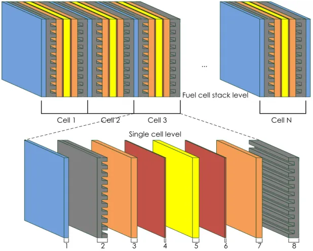
In this section, the presented PEMFC dynamic model is based on a developed multi-physical PEMFC model in the previous works [9]-[10]. The PEMFC stack level and the single cell level are shown in the Figure 1.1. As shown in Figure 1.1, one fuel cell stack level can be separated into eight cell layers, which consist of:
1) Cathode cooling channel layer; 2) Cathode gas supply channel layer; 3) Cathode gas diffusion layer;
4) Cathode catalyst layer;
5) Proton exchange membrane layer; 6) Anode catalyst layer;
7) Anode gas diffusion layer;
16
...
Cell 1 Cell 2 Cell 3 Cell N
1 2 3 4 5 6 7 8
Fuel cell stack level
Single cell level
Figure 1.1 PEMFC stack level and the single cell level
The advantage of this cell layer structure is that each modeling layer can be described separately by its own physical equations and the boundary conditions. Each cell layer is considered as a control volume in the presented model. For each cell layer, the modeling of different physical domain is presented in the following subsections.
1.2.1 Electrical Domain Modeling
As an electricity-converting device, the PEMFC converts fuel energy into electricity through electrochemical reactions. Therefore, the electric domain is included in the proposed PEMFC model.
The total output voltage of a single-cell can be calculated by the following equation:
where is the single fuel cell thermodynamic voltage (V), is the ohmic voltage drop (V), is the cell activation voltage drop (V).
17
where is the catalyst layer temperature (K), is the Faraday constant (C/mol), is the ideal gas constant, is the oxygen pressure (atm) at the interface of cathode catalyst layer, is the hydrogen pressure (atm) at the interface of anode catalyst layer (please refer to the last paragraph of this section). The membrane resistance (Ω) is calculated by [12]:
where is the section surface of membrane (m2), is the membrane thickness
(m). is the resistivity of membrane (Ω m) which can be calculated by the following equation [12]:
Thus, the cell ohmic voltage drop can be calculated from Ohm’s law equation [13]:
The electrochemical activation voltage drop of single cell can be calculated by Butler-Volmer equation [14]:
where is the stack current (A), is the charge transfer coefficient, is the electrons number. The exchange current density (A/m2) can be calculated by an empirical
equation [15]:
where and are empirical parameters, is the oxygen activation energy on the electrode catalyst interface. It should be noted that, the in anode side for fuel cells
of PEMFC type can be neglected due to the easy electrochemical process.
It can be seen from the equation 1.6 that, the term activation voltage drop is in an implicit form. In order to explicitly calculate this non-linear implicit Butler-Volmer equation
18 to obtain the value of , an iterative solver is used. For a high stack current, the
Butler-Volmer equation can be written as the well-known Tafel equation [16]:
The dynamic behavior of activation losses voltage in the electrical domain due to the “double layer effect” can be expressed by:
1.2.2 Fluidic Domain Modeling
It should also be noted that, since the and used in equation 1.2 are
reactant gas pressure at the catalyst layer interface instead of the gas supply channels, another fuel cell over-potential term due to pressures drop through the GDL, well known as “concentration losses”, has been already implicitly considered in the proposed fluidic model. Therefore, the fluidic behaviors inside fuel cell, such as reactants convection in the channels and diffusion through gas diffusion layer, have a great impact on fuel cell performance. In this section, the fluidic domain modeling is presented.
1.2.2.1 Cooling Channels
In the gas channel, the Reynolds number can be calculated by the following equation [17]:
where is the channel hydraulic diameter (m), is the mean fluid velocity in the channel (Pa s). The mean velocity (m/s) of gas can be calculated based on the following equation:
where is the fluid mass flow (kg/s), A is the total section of cooling channels (m2). The
fluid density (kg/m3) can be calculated by ideal gas equation of state:
The gas pressure drop of serpentine channel depends on the surface friction losses
19 with
where , and are respectively the pressure at inlet, outlet, and center of cooling channel, is the total length of straight channel (m), is the Darcy
friction factor which can be obtained from the empirical equation [19]:
The gas pressure dynamic response in the fuel cell is generally due to the channels volume. Thus, the dynamic behaviors of fluid in the cooling channel can be given by the mass balance equation:
where is the gas molar mass (kg/mol), is the volume of the cool channels (m3), is the cooling channel temperature (K), is the gas pressure in the cool channels
(Pa) and is the fluid mass flow rate (kg/s) entering or leaving the channels.
1.2.2.2 Gas Supply Channels
The total pressure of the center of the gas supply channels can be calculated by:
where , , are respectively the oxygen, nitrogen, and vapor pressure in the center of cathode supply channel. , are respectively the hydrogen and
vapor pressure in the center of anode supply channel. The gas pressure in the center of channels is defined as follow:
where is the gas pressure at the channel inlet, and is the gas pressure at the channel outlet. Thus, the dynamic behaviors of fluid in the center of gas supply channels can be also written based on the mass balance equation:
20
where is the gas mass flow at the inlet of channel, is the gas
mass flow at the outlet of channel, is the volume of the gas supply channels (m3)
and is the temperature of gas supply channel (K).
1.2.2.3 Gas Diffusion Layer (GDL)
To obtain the reactant gas pressure at interface of the catalyst layer, the diffusion phenomenon in the gas diffusion layer can be described by modified Fick's law [20] [21]:
where is pressure of specie x in gas diffusion layer (Pa), is thickness of gas
diffusion layer (m), is the gas diffusion layer temperature (K), is the gas molar flow rate of specie x (mol/s), is the gas diffusion layer area (m2), is the gas
diffusion coefficient (m2/s) between the species x and y can be calculated from [22]:
where is the total pressure of species (atm), is the critical temperature of species
(K), is the critical pressure of species (atm), and is the molar mass of species
(kg/mol), is the porosity of the GDL and is the GDL tortuosity. The coefficients and depend on whether one of the species is a polar gas or not and are determined accordingly, which are given as follows [22]:
For pair of gases contains no polar gas:
For pair of gases contains polar gas:
1.2.2.4 Catalyst Layers
As mentioned before, the reactant gas mass flow rate through the GDL to the catalyst layer is directly proportional to the fuel cell stack current [23] [24]. Thus, the oxygen mass flow (kg/s)at the cathode side can be expressed by:
21
the hydrogen mass flow (kg/s)at the anode side can be expressed by:
and the mass flow of produced water (kg/s) at the cathode side due to the electrochemical reaction can be calculated by:
1.2.2.5 Dynamic Membrane Water Content
Because the membrane ionic conductivity is highly dependent on water content
in polymer membrane [25], a more detailed knowledge of transient behavior of the would give a more accurate value of Ohmic losses , as shown in the equation
1.3. Moreover, the dynamic phenomena of plays an important role on the dynamic performance of PEM fuel cell due to its relatively long transient time (up to some minutes) [26].
The dynamics of the membrane water content is generally influenced by two water flow effects in the membrane: the electro-osmotic drag flow due to proton conduction from the anode to the cathode; the water back diffusion flow caused by the concentration gradient between anode and cathode side. The membrane water content is defined as the relationship of the number of water molecules per charged site (sulphonate site) [27]:
where is the water activity factor, which can be obtained based on the water local vapor partial pressure (pa), and the local vapor saturation pressure (pa):
where the local vapor saturation pressure is calculated by:
22 where is the vapor temperature (K). Thus, the dynamics of the water content in
the membrane can be obtained by considering the water molar flows balance at two sides (i.e. anode and cathode) of membrane, and the mass conservation of water, as shown in Figure 1.2. Gas supply channel Gas supply channel GDL GDL Cathode Anode(dead-end) C a ta ly st C a ta ly st Membrane hum
w
outletw
GDL chw
ch GDLw
ca GDLw
mem ca diffw
, w
diff,meman draw
prow
ca
w
anFigure 1.2 Dynamic water flow behaviors in fuel cell membrane.
Thus, the dynamics of the water content can be described by:
where is the membrane dry density (kg/m3), is the molecular mass of
membrane (kg/mol), and represents different water molar flow (mol/s) entering or leaving the membrane due to electro-osmotic drag and water back diffusion flow. The water molar entering or leaving the membrane due to electro-osmotic drag can be described by:
where the is the coefficient of electro-osmotic drag for maximum hydration
conditions. The water molar entering (from cathode to membrane) or leaving (from membrane to anode) the membrane due to back diffusion flow can be described by [28]:
23
where is the dry density of the membrane (kg/m3), is the equivalent mass
of the membrane (kg/mol). The boundary water content at anode and cathode side can be expressed as a function of water activity which can be deduced from the water vapor partial pressure equation 1.28. The membrane water diffusion coefficient
(m2/s) can be calculated from the empirical equations [28]:
As shown in Figure 1.2, in the case of non-humidified hydrogen supply and anode dead-end mode operation, the anode side water accumulation is only caused by the water diffusion from the membrane to the anode , and the cathode side water accumulation depends on three factors: comes from humidified air supply at cathode , the produced water at cathode side during electrochemical reaction and the electro-osmotic drag flow from the anode to the cathode .
Under the dead-end mode operation (no water accumulation at anode side), the water molar flow entering into the membrane from anode due to electro-osmotic drag
is equal to the water molar flow leaving out the membrane to anode due to
back-diffusion (dashed portion as shown in figure 1.2). Thus, the dynamics of
the membrane water content can thus be simplified by:
with anode side water content :
1.2.3 Thermal Domain Modeling
In addition to the fluidic phenomena, the effect of temperature on the fuel cell performance should also be considered in the fuel cell modeling. For example, the heat transfer changes the gas convection and diffusion behaviors, and further influences the electrochemical quantities inside the fuel cell.
24 The fuel cell temperature transient behavior in the thermal domain is due to the heat generation and thermal conduction and convection phenomena. Like dynamic behavior of membrane water content, dynamics of fuel cell temperature is an important phenomenon due to its relatively long transient time. This dynamic behavior can be generally described as follows:
where is the mean layer volume density of stack (kg/m3), is the layer volume of stack
(m3), is the layer thermal capacity (J/kg K), is the temperature (K) of each control
volume and stands for the different types of heat (J) flows entering or leaving the layer respectively: conduction, convective flow, forced convection and internal heat sources. The heat flows due to conduction can be expressed according to Fourier’s law [29]:
where is the control volume thermal conductivity (W/m K), is the section of the control volume in heat transfer direction (m2), and is the control volume thickness
(m).
The convective heat flow due to the mass transfer entering or leaving the control volume can be calculated by
where is the mass flow rate (kg/s).
The heat transfers by forced convection can be written according to Newton’s cooling law:
where is the coolant temperature and is the contact area (m2), is the
forced convection heat transfer coefficient (W/m2 K), which can be calculated by [29]:
where is the fluid thermal conductivity, is the Nusselt number of the fluid, which can be calculated by the empirical equations [30]:
25
Where is the coolant thermal capacity (J/kg K).
At last, the linear expression of the heat sources as a function of the cell temperature can be obtained:
1.3 Multi-Dimensional Modeling Considerations
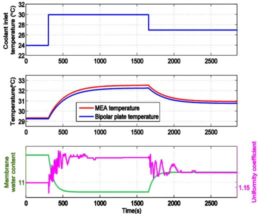
Compared with 1-D models [31]-[39], a 2-D PEMFC model has a capability to provide two-dimensional behaviors, which is very useful for spatial non-uniformity and control coupling analysis. This analysis can give detailed and valuable spatial physical quantity information under different fuel cell operation conditions by taking multiple spatial dimensions into consideration. For example to prevent local “hotspot” on electrode due to non-homogeneous distribution of reactants, and can be further employed in a model-based real-time controller.
Many PEMFC 2-D models have been previously proposed in the literature [40]-[45]. However, a common drawback of these works is that the presented fuel cell bipolar plate flow field (gas channels) models are over-simplified (or not even considered). Thus they cannot accurately describe the non-linear and non-uniform pressure distribution characteristics.
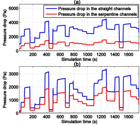
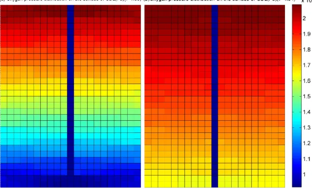
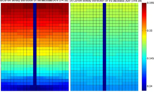
For example, as shown in the upper part of figure 1.3, the gas pressure prediction results of a model without the consideration of channel geometric form, could lead to an inaccurate gas diffusion phenomenon in the serpentine pipeline, which would further impact the accuracy of electrode current density analysis. In these models, the gas supply channel is assumed to be straight and single. In fact, the gas supply pipeline in the anode and cathode sides have different geometric patterns, as shown in the figure 1.4.
26 Cathode gas supply channel Anode gas supply channel Cooling channel Inlet Outlet Inlet Outlet
Figure 1.3 Double three-parallel serpentine pattern of cathode gas supply channel and double single serpentine pattern of anode gas supply channel
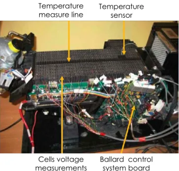
It can be seen from the figure 1.4 that, the flow field forms of a Ballard NEXA 1.2kW fuel cell stack used in this thesis includes a single serpentine pipeline in anode side and a parallel serpentine pipeline in cathode side. Therefore, a comprehensive representation of non-homogeneous gas phenomenon by fully taking the geometric form of the fuel cell pipeline into consideration is particularly useful to achieve highly accurate spatial distribution information for 2-D model of PEMFC.
Figure 1.4 Actual geometry form of gas channel of NEXA PEMFC:
27 In this section, a 2-D, multi-physical PEMFC model is fully developed, which covers fluidic and electric domains with an innovative 2-dimensional modeling approach. The basis of individual layers in a single cell of the proposed 2-D PEMFC model is shown in the figure 1.5.
It can be seen from the figure 1.5 that, in the proposed 2-D PEMFC model, a single cell model consists of 7 individual layers: 1) cathode gas supply channel; 2) cathode gas diffusion layer (GDL); 3) cathode catalyst layer; 4) membrane; 5) anode catalyst layer; 6) anode gas diffusion layer (GDL); 7) anode gas supply channel.
1
2
3 4
5
6
7
Figure 1.5 Structure of a single cell of fuel cell stack.
In order to take the geometric form of the fuel cell pipeline into consideration, a 2-D modeling of fluidic domain is developed firstly, followed by a 2-D electric modeling.
1.3.1 Two-Dimensional Approach in Fluidic Model
To accurately model the reactant gas pressure distribution on the electrodes surface, a comprehensive modeling of gas convection-diffusion phenomena in the gas supply channel and GDL is presented hereafter by precisely considering the fuel cell gas channel geometric form in this section.
1.3.1.1 Gas Supply Channels
Different from single and straight channel assumption in the previously developed PEMFC model, the geometric patterns of gas supply channels (both anode and cathode sides) are now considered in the improved model, such as single serpentine, parallel serpentine channels, with the consideration of sharp and curved U-bends (channel angles). Under the same inlet air supply conditions, the gas pressure distribution on the surface of GDL depends highly on the flow field form. Thus, a detailed
28 representation of non-homogeneous gas pressure distribution by considering the flow field form can be very useful to achieve accurate modeling results.
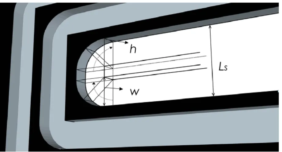
In this thesis, the geometric form of gas supply channels is taken from Ballard NEXA fuel cell as shown in figure 1.6. This two-sided design includes a three-parallel serpentine channel for cathode air supply, and a single serpentine pattern channel for anode hydrogen supply. Inlet Inlet Outlet Outlet Cathode channel Anode channel
Figure 1.6 Three-parallel serpentine channel for cathode air supply; and single serpentine channel for anode hydrogen supply.
The gas pressure drop of serpentine channel depends on three factors [46] [47]: the
surface friction losses of straight pipeline (modeled by the Darcy–Weisbach equation), the frictional loss suffered in the elongated section of the bends, and the sum of excess loss coefficients for n U-bends:
where is the Darcy friction factor, is the fluid density in the channel (kg/m3), is
the total length of straight channel (m), is the mean fluid velocity in the channel (m/s),
is the hydraulic diameter of the channel (m), is the total length of elongated
section of the bends (m), the Kays friction factor can be given by [46]:
29 where is the pipeline width (m), is the pipeline thickness (m). is the Reynolds number of the fluid in the channels, channel aspect ratio is defined by:
The excess bend loss coefficient of i th bend is given by [46]:
where is the spacer length between two neighboring duct, and is the curvature ratio of the bend, is given by [46]:
where is the mean radius of bends, is the duct hydraulic diameter which is calculated by:
where the pipeline width , pipeline thickness , and spacer length between two neighboring duct can be seen clearly in the figure 1.7.
From figure 1.7, the rectangle pane is represented as the cross sectional area of pipeline. The anode channel curved U-bends are the same as those in the cathode channel.