HAL Id: tel-01356708
https://tel.archives-ouvertes.fr/tel-01356708
Submitted on 26 Aug 2016HAL is a multi-disciplinary open access archive for the deposit and dissemination of sci-entific research documents, whether they are pub-lished or not. The documents may come from teaching and research institutions in France or abroad, or from public or private research centers.
L’archive ouverte pluridisciplinaire HAL, est destinée au dépôt et à la diffusion de documents scientifiques de niveau recherche, publiés ou non, émanant des établissements d’enseignement et de recherche français ou étrangers, des laboratoires publics ou privés.
in quiescent and turbulent flow conditions
Maria Luis Gracio Bilro Castela
To cite this version:
Maria Luis Gracio Bilro Castela. Direct Numerical Simulations of plasma-assisted ignition in qui-escent and turbulent flow conditions. Plasmas. Université Paris-Saclay, 2016. English. �NNT : 2016SACLC042�. �tel-01356708�
THÈSE DE DOCTORAT DE
L’UNIVERSITÉ PARIS-SACLAY
préparée à CentraleSupélec ÉCOLE DOCTORALE No579
Sciences mécaniques et énergétiques, matériaux et géosciences Spécialité de doctorat Combustion
Présentée par
MARIA LUÍS GRÁCIO BILRO CASTELA
DIRECT NUMERICAL SIMULATIONS OF
PLASMA-ASSISTED IGNITION IN QUIESCENT AND
TURBULENT FLOW CONDITIONS
Thése soutenue à Châtenay-Malabry, le 12/05/2016 Composition du jury:
S. Pasquiers Directeur de Recherche CNRS, LPGP Président P. Domingo Directrice de Recherche CNRS, CORIA Rapporteur D. Thévenin Prof. Otto von Guericke University Magdeburg Rapporteur
B. Cuenot Chercheur Senior CERFACS Examinateur
B. Fiorina Prof. CentraleSupélec, EM2C Directeur de thèse
N. Darabiha Prof. CentraleSupélec, EM2C Co-Directeur de thèse
C. O Laux Prof. CentraleSupélec, EM2C Co-Directeur de thèse
O. Gicquel Prof. CentraleSupélec, EM2C Co-Directeur de thèse
Laboratoire d’Énergétique Moléculaire et Macroscopique, Combustion CNRS, CentraleSupélec.
Plasma-assisted combustion has received increasing attention in both plasma and combustion communities. Nanosecond Repetitively Pulsed (NRP) discharges are a promising and efficient technique to initiate and control combustion processes particularly when conventional ignition sys-tems are rather ineffective or too energy costly. Even though a promis-ing technique, the phenomena occurrpromis-ing in NRP discharges-assisted com-bustion are still poorly understood. The numerical studies presented in the literature are limited to 1-D and 2-D simulations in quiescent con-ditions. The problem complexity increases in practical configurations as ignition phenomena are also controlled by the flow and mixing field characteristics in and around the discharge channel. Direct Numeri-cal Simulations (DNS) is a powerful research tool to understand these plasma/combustion/flow interactions. However, the computational cost of fully coupled detailed non-equilibrium plasma and combustion chem-istry, and high Reynolds number simulations is prohibitive.
This thesis presents a model to describe the effects of non-equilibrium plasma discharges in the set of equations governing the combustion phe-nomena. Based on the results reported in the literature, the model is constructed by analyzing the channels through which the electric energy is deposited. The two main channels by which the electrons produced during the discharge impact the reactive mixture are considered: 1) the excitation and the subsequent relaxation of the electronic states of nitro-gen molecules, which leads to an ultrafast increase of the gas tempera-ture and dissociation of species; and 2) the excitation and relaxation of vibrational states of nitrogen molecules which causes a much slower gas heating. This high level model of NRP discharges allows DNS studies of plasma-assisted combustion / ignition in high turbulent Reynolds num-ber. The complex physics underlying plasma-assisted ignition by multiple discharges in both quiescent and turbulent flow conditions are discussed in the present thesis.
La combustion assitée par plasma a reçu une attention croissante dans les deux communautés de plasma et de combustion. Les décharges Nanosec-onde Répétitive Pulsée (NRP) sont des techniques prometteuse et effi-caces pour initier et contrôler les processus de la combustion en particulier quand les systèmes d’allumage conventionnels sont inefficaces ou trop coû-teux en énergie. Néanmoins, les phénomènes rencontrés dans la combus-tion assistée par plasma sont encore mal connus. Les études numériques présentées dans la litérature sont limitées á des simulations 1-D et 2-D dans des conditions au repos. La complexité du problème augmente dans les configurations pratiques oú le phénomène d’allumage est contrôlé par le mouvement du fluide ainsi que le mélange autour de la zone de décharge. La simulations numérique directe (DNS) est un outil de recherche puissant pour la compréhension des interactions plasma/combustion/écoulement. Toutefois, le coût de calcul de la combustion turbulente avec un nombre de Reynolds élevé et la cinétique chimique détaillée couplée avec le plasma hors-équilibre est prohibitif.
Cette thèse présente un nouveau modèle de couplage plasma-combustion pour introduire les effets des décharges de plasma hors-equilibre dans le système d’équations qui décrit le phénomène de la combustion. Le mod-èle est construit en analysant les chemins par lesquels l’énergie électrique est transferrée au gaz. Ce modèle de décharges NRP permet des simu-lations multidimensionales DNS de la combustion et l’allumage assistés par plasma. Les phénomènes physiques complexes de l’allumage assisté par décharges multiples de plasma dans des dans mélanges au repot et en regime d’écoulement turbulent sont analysés dans cette thèse.
Abstract iii
Résumé v
List of Publications ix
1 Introduction 1
1.1 Challenges of Novel Combustion Technologies . . . 3
1.2 Fundamentals and background studies of plasma-assisted combustion . . . 8
1.3 Motivations and aim of the present work . . . 20
1.4 Outline of the Dissertation . . . 22
2 Phenomenological Model for Non-equilibrium Plasma Dis-charges in Reactive Mixtures 23 2.1 Introduction . . . 25
2.2 Conservation equations for reactive flows without plasma discharges . . . 26
2.3 Review of plasma-assisted combustion models . . . 29
2.4 Phenomenological plasma-assisted combustion model . . . 37
2.5 Model closures . . . 48
3 DNS solver and 2-D DNS of NRP discharges in air 65 3.1 Introduction . . . 67
3.2 DNS solver . . . 68
3.3 2-D DNS of NRP discharges in air. . . 71
3.4 Conclusions . . . 79
4 2-D DNS of NRP discharge-assisted ignition in quiescent and turbulent flow conditions 83 4.1 Introduction . . . 85
4.2 Test-cases description and numerical set-up. . . 85
4.3 2-D DNS of NRP discharges in methane-air mixture in qui-escent conditions . . . 87
4.4 2-D DNS of NRP discharges in methane-air in turbulent flow conditions . . . 92
4.5 Conclusions . . . 104
5 Study of the recirculating flow pattern effects inside a re-active kernel produced by nanosecond plasma discharges in a methane-air mixture: 3-D DNS and experiments 107 5.1 Introduction . . . 109 5.2 Test-case description . . . 112 5.3 Results . . . 118 5.4 Conclusions . . . 126
Conclusion and Perspectives 129 A Estimation of the computational costs of DNS plasma-assisted ignition (YWC code) 135 A.1 Estimation of the number of points Npts . . . 137
A.2 Estimation of the number of iterations Nite . . . 138
The work developed in this thesis was the object of two publications in peer-reviewed journals and several presentations in international confer-ences:
Peer-reviewed journals
M. Castela, S. Stepanyan, B. Fiorina, A. Coussement, O. Gicquel, N. Darabiha, C. O. Laux, A 3-D DNS and experimental study of the effect of the recirculating flow pattern inside a reactive kernel produced by nanosec-ond plasma discharges in a methane-air mixture, Accepted for publication in the Proceedings of the Combustion Institute - Seoul, Korea (2016). M. Castela, B. Fiorina, A. Coussement, O. Gicquel, N. Darabiha, C. O. Laux (2016), Modelling the impact of non-equilibrium discharges on reactive mixtures for simulations of plasma assisted ignition in turbulent flows, Combustion and Flame, 166, pp 133-147 .
Peer-reviewed conference publications
M. Castela, B. Fiorina, A. Coussement, O. Gicquel, N. Darabiha, C. O. Laux, Mini-symposium on Safety related ignition processes, 15th
Interna-tional Conference on Numerical Combustion (ICNC15), Avignon, France, April 19-22, (2015).
M. Castela, B. Fiorina, A. Coussement, O. Gicquel, N. Darabiha, C. O. Laux, Modelling the effects of non-equilibrium discharges on reactive mixtures, ATW Fundamentals of Plasma Assisted Combustion and Flow Control - Les Houches, France, April 12-17, (2015).
M. Castela, B. Fiorina, A. Coussement, O. Gicquel, N. Darabiha, C. O. Laux, Impact of nanosecond repetitively pulsed electric discharges on the
ignition of methane-air mixture, 7th European Combustion Meeting
(ECM2015) - Budapest, Hungary, March 30 - April 2, (2015).
M. Castela, B. Fiorina, A. Coussement, O. Gicquel, N. Darabiha, C. O. Laux, Modelling the impact of plasma discharges on turbulent reactive mixtures, International Conference organized by the Portuguese and Spanish Sections of the Combustion Institute - Lisbon, Por-tugal, November 19-21, (2014).
M. Castela, B. Fiorina, A. Coussement, O. Gicquel, N. Darabiha, C. O. Laux, Direct numerical simulations of combustion assisted by dis-charges in quiescent and turbulent flow conditions, 10th International
ERCOFTAC Symposium on Engineering Turbulence Modelling and Measurements (ETMM10) - Marbella, Spain, September 17-19, (2014).
M. Castela, B. Fiorina, A. Coussement, O. Gicquel, N. Darabiha, C. O. Laux, Direct numerical simulations of pulsed discharges assisted com-bustion in quiescent and turbulent flow conditions, 10th International
Symposium on special topics in chemical propulsion (ISICP-10) - Poitiers, France, June 2-6, (2014).
Awards
Best poster award at RED - Reencontre Entreprise Doctorants, Centrale-Supélec - France (2014)
1.1 Schematic comparison of the electron temperatures and re-duced electric fields for different discharges: DC: direct current discharges, MW: microwave discharges, DBD: di-electric barrier dischargees, RF radio frequency discharges. Reproduced from Sun (2013). . . 11
1.2 Comparison of OH (A-X) emission with and without dis-charge after Abel transform; air: 14.7 m3 h 1 , propane:
0.5 m3 h 1 ( = 0.83). Flame power: 12.5 kW, discharge
power: 75 W. Emission of the plasma was blocked to pre-vent saturation of the ICCD. Reproduced from Pilla et al. (2006). . . 13
1.3 Single-shot schlieren images capturing the hydrodynamic effects induced by a single NRP discharge in air. Repro-duced from Xu (2013) . . . 16
1.4 Single-shot schlieren images capturing the hydrodynamic effects induced by a train of 10 nanosecond discharges in air applied at pulse repetition frequency of 30 kHz. Repro-duced from Xu (2013) . . . 16
2.1 Schematic representation of the discharge energy deposi-tion rate model. . . 32
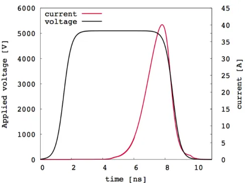
2.2 Typical voltage model for a discharge with applied voltage of 5.1 kV, a maximum conductive current of 40 A and a pulse duration of 10 ns with a rise and a decrease time of 2 ns. Reproduced from Tholin (2012). . . 33
2.3 Example of the set of plasma-related reactions used in de-tailed plasma-assisted combustion models. The notation indicates that an electron impact cross-section is used in BOLSIG+ to determine the rate coefficient. Reproduced from Bak et al. (2012) . . . 35
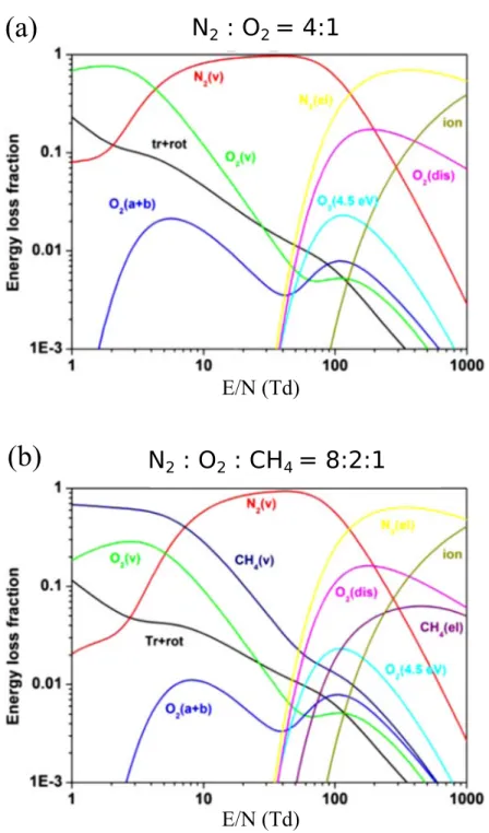
2.4 Fractional power dissipated by electrons into various chan-nels as a function of E/N. (a) Air; (b) methane-air sto-ichiometric mixture. Reproduced from Starikovskiy and Aleksandrov (2013). . . 38
2.5 Comparative schemes of the energy pathways and charac-teristic time scales considered in detailed plasma models and the ones considered in the present model. In the new model detailed plasma chemistry is by-passed. . . 42
2.6 Schematic representation of the energy source terms con-sidered in the present model formulation. The discharge energy is assumed to be deposited into (a) gas chemical, (b) thermal and (c) vibrational energies within the pulse characteristic time ⌧pulse. The relaxation of vibrational
en-ergy leads to (d) a slower increase of gas thermal enen-ergy within a characteristic time ⌧V T. . . 44
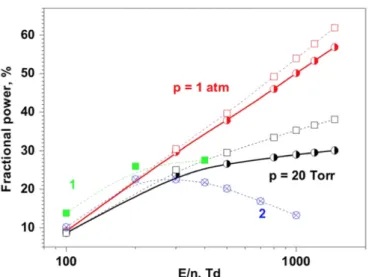
2.7 The fraction of the total electron power transferred into heat in dry air at 20 Torr and 1 atm as a function of the reduced electric field at which the energy was deposited in a high-voltage nanosecond discharge. The calculations were carried out for nef = 1015cm 3(solid curves) and 1014
cm 3 (dash curves). Curve 1 corresponds to calculations
of Flitti and Pancheshnyi (2009) and curve 2 corresponds to the calculations of Popov (2001) assuming that 28% of the energy that was spent on the excitation of electronic N2 and O2 states was quickly transferred into gas heating.
Reproduced from Aleksandrov et al. (2010). . . 49
2.8 Temporal parameters considered in the phenomenological model to set the frequency of the discharge energy deposi-tion rate for simuladeposi-tions of nanosecond repetitively pulsed discharges. . . 55
2.9 Spatial parameters considered in the phenomenological model to set the shape and location of the discharge energy de-position rate in the computational domain. . . 55
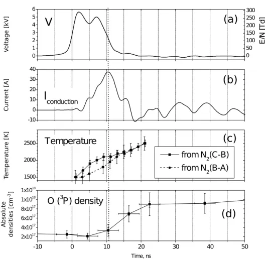
2.10 Measurements of (a) pulse voltage and corresponding re-duced electric field E/N, (b) conduction current, (c) tem-perature and (d) O density. These data were obtained for the reference conditions: atmospheric pressure air pre-heated at 1000 K, V = 5.7 kV, gap distance = 4 mm, pulse frequency = 10 kHz, air flow velocity = 2.6 ms 1 and
en-ergy per pulse = 670 ± 50 µJ. Reproduced from Rusterholtz et al. (2013). . . 58
2.11 Measured radial profiles at t = 9 ns of the N2(B) and N2(C)
density. Reproduced from Rusterholtz et al. (2013). . . 59
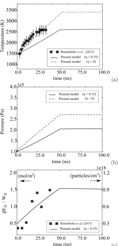
2.12 Temporal evolution of the maximum value of (a) gas tem-perature, (b) pressure and (c) O radical concentration dur-ing the pulse. Model results are compared with the exper-imental results obtained in Rusterholtz et al. (2013). . . . 63
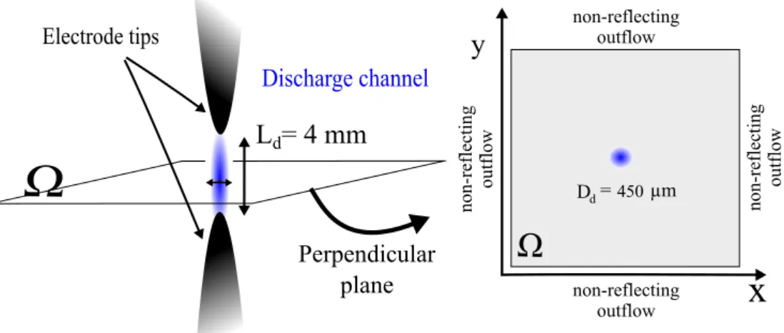
3.1 Schematic of a pin-to-pin configuration of NRP discharges device. The 2-D computational domain is a plane perpen-dicular to the inter-electrode axis. . . 72
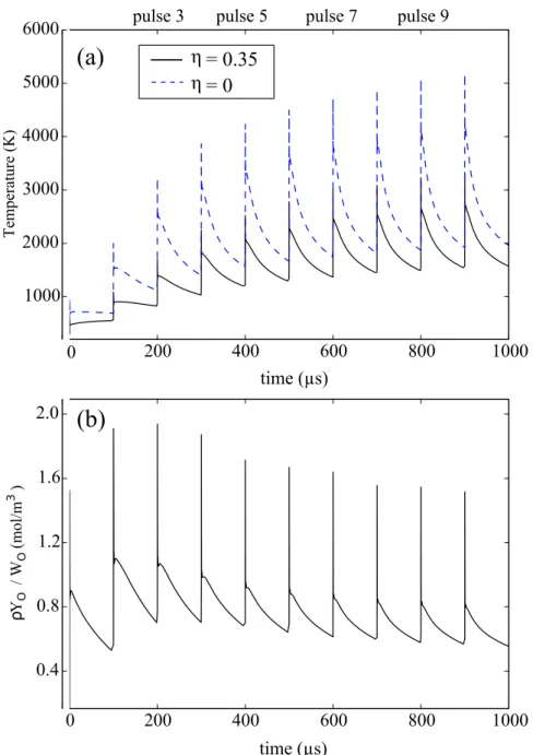
3.2 Temporal evolution of (a) the gas temperature and (b) the oxygen concentration at the centre of the discharge channel in a sequence of 10 pulses in air. The following parameter values were used: pulse repetition frequency f = 10 kHz, energy density per pulse pulse = 1.1⇥106 J/m3 and model
parameters: ↵ = 0.55 and two values of ⌘: 0.35 and 0.. . . 75
3.3 Temporal evolution of (a) gas thermal plus chemical energy normalised by the energy of a single discharge; and (b) gas vibrational energy; in a sequence of NRP discharges in air for two values of the model parameter ⌘. . . 77
3.4 Time series of the (a) pressure wave and (b) the gas density radial profiles after the 5th pulse. Two values of the model
parameter ⌘ are considered: ⌘ = 0 and ⌘ = 0.35. . . 80
3.5 Temporal evolution of the radial position of the pressure wave and the heated channel after the 5thpulse. Two values
of the model parameter ⌘ are considered: ⌘ = 0.35 and 0. . 81
4.1 Temporal evolution of the maximum value of gas tempera-ture. Mixture ignites after two discharges if ⌘ = 0.35 (solid line) whereas four discharges are needed if ⌘ = 0 (dashed line). . . 89
4.2 Radial profiles of species concentrations considering the ul-trafast O2dissociation during the discharge pulses, ⌘ = 0.35.
Results are presented at 4 different instants (a) at the end of the first pulse - t = 50 ns, (b) immediately before the second pulse at t = 100 µs, (c) at the end of the second pulse - t = 100 µs + 50 ns and (d) after the mixture igni-tion when the flame kernel propagates outwards from the centre of the discharge channel. . . 91
4.3 Radial profiles of species concentrations when the ultrafast O2 dissociation during the discharge pulses is not
consid-ered, ⌘ = 0. Results are plotted at 4 different time instants (a) at the end of the third pulse - t = 200 µs + 50 ns, (b) immediately before the fourth pulse - t = 300 µs, (c) at the end of the fourth pulse - t = 300 µs + 50 ns, and (d) after mixture ignition when the flame kernel propagates outwards from the centre of the discharge channel. . . 93
4.4 Flow characteristics at the beginning of the computations: a) vorticity field; and velocity field at b) Relt = 44 and c)
Relt = 395. . . 95
4.5 Impact of turbulence on the temporal evolution of the gas temperature in the near-field of the discharge zone for a turbulent flow characterised by Relt = 44. The time
in-stants captured correspond to (a) the end of the first charge t = 50 ns, (b) the beginning of the second dis-charge t = 100 µs, (c) the end of the second disdis-charge t = 100 µs + 50 ns and (d) t = 200 µs. . . 97 4.6 Impact of turbulence on the temporal evolution of the gas
temperature in the near-field of the discharge zone for a turbulent flow characterised by Relt = 395. The time
instants captured correspond to (a) the end of the first discharge t = 50 ns, (b) the beginning of the second dis-charge t = 100 µs, (c) the end of the second disdis-charge t = 100 µs + 50 ns and (d) t = 200 µs. . . 97 4.7 Impact of turbulence on temperature field at Relt = 395.
Four time instants are captured within each pulse period for a sequence of four discharge pulses. Mixture ignition occurs only after four discharge pulses. . . 98
4.8 Impact of turbulence on CH2O mass density and gas
vi-brational energy density at the beginning and at the end of three consecutive discharges. . . 99
4.9 Initial vorticity fields in four turbulent events characterized by the same turbulent Reynolds number Relt = 395. The
initial spatial distribution of the turbulent eddies, relative to the discharge zone (identified by the black square), is changed at the beginning of the computations. . . 100
4.10 Temporal evolution of the maximum value of gas temper-ature inside the computational domain (dashed lines) and gas temperature at the centre of the discharge zone (solid lines) in four different initial conditions of the velocity field. Results are compared to quiescent flow condition (dotted lines). . . 101
5.1 Numerical results of the temperature distribution in the spark gap at t = 100 µs. Spark gap of 1.6 mm. Reproduced from Kono et al. (1988). . . 110
5.2 Schlieren photographs taken by 5 ⇥ 105 fps movie in air.
Spark energy: 4.6 mJ. Reproduced from Kono et al. (1988).
. . . 110
5.3 Schematic representation of the combustion chamber and the electric circuit used in the present study. Adapted from Xu et al. (2015). . . 113
5.4 Measured voltage and current waveforms during and after a single discharge in air. . . 115
5.5 Schematic representation of the 3-D computational domain used in the present work: a) solution domain and boundary conditions. b) mesh size distribution over the line AA0. . . 115
5.6 Schematic representation of the shape and the location where the energy of the discharge is deposited in the 3-D computational domain. . . 116
5.7 Temporal evolution of the pressure wave and hot kernel radius at early instants after the discharge pulse. Symbols: experiments; Lines: computations. . . 118
5.8 Hot kernel topology captured at t = 0.3 µs and t = 2 µs af-ter the plasma discharge in methane-air mixture: a) Exper-imental (left-half) and computational (right-half) schlieren images. b) Superposition of the computed gas temperature field and flow streamlines coloured by velocity magnitude. The same color map of velocity magnitude is used in for all images shown here, but the maximum value Vmaxvaries
5.9 Hot kernel topology captured at t = 9 µs, t = 80 µs and t = 200 µs after the plasma discharge in methane-air mix-ture: a) Experimental (left-half) and computational (right-half) schlieren images. b) Superposition of the computed gas temperature field and flow streamlines coloured by ve-locity magnitude. The same color map of veve-locity magni-tude is used in for all images shown here, but the maximum value Vmax varies and is indicated above each image. . . . 121
5.10 3-D plot of the OH mass fraction at 6 instants following the discharge pulse. The initial cylinder-shaped hot kernel evolves into a toroidal shape.. . . 122
5.11 Influence of gas recirculation on the evolution of the hot kernel radius . – With gas recirculation (3D DNS), -Without gas recirculation (2-D DNS). . . 123
5.12 Species mass fractions profiles along the line AA0 depicted
in Fig. 5.5. Species radial profiles plotted on the left side refer to the 3-D DNS case (with gas recirculation), whereas the profiles plotted on the right side refer to the 2-D DNS case (without gas recirculation). . . 125
A.1 Value of the Cef f for the YWC DNS solver as a function
of the number of species considered in the kinetic scheme.. 136
A.2 Schematic representation of the strategy to estimate Npts,
Introduction
This chapter provides an overview of the current challenges in combustion systems for which plasma-assisted combustion is a promising technology. The main characteristics of plasma dis-charges are presented with emphasis on short repetitively-pulsed discharges. Because of its characteristics, simulations of plasma-assisted combustion present additional challenges. To tackle these challenges, several strategies were developed and published in the literature and will be presented and discussed here. We also high-light in this chapter, some open questions regarding the modelling and the physics occurring in plasma-assisted combustion, some of which providing the motivation for this thesis.
Contents
1.1 Challenges of Novel Combustion Technologies 3
1.1.1 Increase of combustion efficiency and control of pollutant emission . . . 4
1.1.2 Air transportation and development of Ram / Scramjet engines for air breathing vehicles . . . 6
1.1.3 Plasma-assisted combustion/ ignition technolo-gies . . . 7
1.2 Fundamentals and background studies of plasma-assisted combustion . . . 8
1.2.1 Ignition processes . . . 8
1.2.2 Equilibrium and non-equilibrium plasmas . . . 9
1.2.3 Thermal, chemical and hydrodynamic effects of NRP discharges . . . 14
1.2.4 Coupling plasma and combustion numerical mod-els . . . 17
1.2.5 Multi-dimensional simulations of single / mul-tiple plasma discharges in reactive mixtures . . 18
1.3 Motivations and aim of the present work . . . 20
1.3.1 Open questions in plasma-assisted ignition . . . 20
1.3.2 Aim of the present thesis . . . 20
1.1 Challenges of Novel Combustion
Tech-nologies
The rising global demand and the scarcity of fossil fuels along with the increasing stringent regulations on pollutant emission and environmen-tal concerns, are the main motivations for the development and/or im-provement of new combustion technologies. Worldwide long-term actions include promoting energy efficiency and the development of alternative fuel technologies to use sustainable fuels, including biofuels, in multiple sectors.
In the following sections some of the solutions investigated for combustion technologies to tackle these major challenges in the automobile, indus-trial and aerospatial/aeronautical sectors are briefly presented. As will be discussed, low-emission and highly-efficient energy technologies are still unable to overcome practical difficulties. Plasma-assisted combus-tion / ignicombus-tion may provide the necessary control, improvement and/or the safety factor for a reliable implementation of these new combustion technologies in practical systems.
The fundamentals of plasma discharges are presented in section1.2where particular attention is given to nanosecond repetitively-pulsed (NRP) dis-charges. Base on the experimental and numerical results reported in the literature, the thermal, chemical and hydrodynamic effects induced by this kind of plasma discharges are described.
State-of-the-art numerical simulations of NRP discharges are then pre-sented in sections 1.2.4 and 1.2.5. As will become clear, state-of-the-art numerical simulations of NRP discharges are mostly limited to one-dimensional simulations which are unable to unveil the physics underlying the ignition phenomena in practical combustion devices.
section 1.3 where the manuscript is also outlined.
1.1.1 Increase of combustion efficiency and control of
pollutant emission
Several solutions have been proposed for industrial burners and automo-tive engines to reduce pollutant and particulate emissions, and to increase engines efficiency. Most of them rely on premixed or partially-premixed lean combustion regimes. As will be discussed below, the effective appli-cation of these new technologies to practical systems is still limited by the capability of controlling ignition and stabilizing the flame over a wide range of operational conditions..
Ground transportation
One of the solutions identified in the automobile industry to reduce soot and NOx emissions (Taylor 2008) is the use of Homogeneous Charged
Compression Ignition (HCCI) (Dec 2009), Partially-Premixed Compres-sion Ignition (PPCI) or Reactivity Controlled CompresCompres-sion Ignition (RCCI) (Reitz and Duraisamy 2015). HCCI combustion engines rely on very lean premixed or partially-premixed combustion, which suppresses fuel-rich zones and consequently reduces soot formation. Lean combustion implies lower in-cylinder peak temperatures and therefore lower NOx emissions.
In HCCI engines, the thermal efficiencies are comparable to those of diesel engines, due to the high compression ratios, and the extremely low NOx
and soot emissions.
The practical implementation of these technologies to transportation en-gines is still limited by the capability to control auto-ignition timing in a wide range of operation conditions (Dec 2009). While in spark ignition (SI) engines the ignition is controlled by the spark-plug discharge timing, and in diesel compression engines the ignition phenomenon is controlled by the fuel intake, the control of ignition in HCCI engines is much more
challenging due to the lack of an external combustion trigger such as the spark or direct fuel injection. In these engines, ignition is generally based on auto-ignition conditions. Therefore, the combustion initiation in HCCI engines depends largely on the chemistry and thermal conditions inside the cylinder. The strategies to control mixture auto-ignition in HCCI, and thus the heat release rate for a wide range of engine operation conditions, include controlling the amount of exhaust gases recirculation (EGR) going into the cylinder (Dec 2009), the fuel stratification (Dec et al. 2011) and the use of variable compression ratios (Ryan et al. 2004). These strate-gies can be applied at the expense of increased mechanical complexity. Advantages of HCCI engines also include the fuel flexibility, provided that certain restrictions on octane and cetane number are respected. Yet, at low loads the temperature inside HCCI engines may drop significantly, leading to the mixture partial burning and increasing unburned HC and CO emissions (Saxena and Bedoya 2013).
Ground power generation
In ground power generation or industrial furnaces MILD or flameless com-bustion regimes are a promising technique (e.g. Cavaliere and Joannon 2004). In these regimes fuel oxidation occurs within a distributed low temperature reaction zone and in ultra-lean conditions. MILD or flame-less combustion regimes are characterized by low CO and NOx emissions
and by a distributed (colourless therefore flameless) reaction zone where the gas temperature and species concentration gradients are much lower than in conventional lean combustion regime, as experimentally observed in e.g. Verissimo et al. (2011). Because of this distributed reaction zone, MILD and flameless combustion regimes are especially suitable in indus-trial furnaces where a homogenous distribution of the gas temperature is desired (glass industry, for example).
only be reached if the inlet velocities of the reactants are high enough to establish recirculation zones inside the combustion chamber. However, increasing the reactant velocities, flame (or a flameless reaction zone) stabilization becomes more difficult. One of the solutions investigated in the literature to overcome these instability issues is to use reversed flow combustion chambers where the burner and the exhaust port are mounted at the same side of the combustion chamber. These geometries increase the flow residence time owing to higher recirculating flow rates. Castela et al. (2012) studied the combustion regimes occurring in a reversed flow combustion chamber. The authors showed that a stable flameless regime could be reached even at ultra-lean conditions and high inlet reactant velocities with this type of combustion chambers. However these reversed flow combustion chambers are not ideal for gas turbine engines. Thus the application of this regime to gas turbine engines or industrial furnaces still relies on the ability to stabilize a highly diluted reaction zone, in ultra-lean conditions for a wide range of operation conditions. The variation of the operation conditions may lead to mixture partial burning or misfire and to an increase of the thermo-acoustic instabilities.
1.1.2 Air transportation and development of Ram /
Scramjet engines for air breathing vehicles
Aeronautical combustion systems
In air transportation, some of the solutions that are currently being inves-tigated to increase aeronautical engines efficiency and to reduce pollutant emission are also associated with lean combustion regimes. The major drawback associated with these solutions is the in-flight relight capability at high altitudes and the increase of the thermo-acoustic instabilities. Mixture ignition and flame stabilization inside an aeronautical engine are especially difficult. For jet engines, the flow velocity at the inlet of the combustion chamber is of the order of 150 m/s which is significantly higher than the turbulent flame velocity. It is therefore necessary to generate
low velocity regions in order to stabilize the flame. A common strategy is to use swirled injection systems to induce flow recirculation and there-fore increase the flow residence time. Other solutions include the staged fuel injection and structural adapted flame holders. However, in lean and low NOx engines design, these solutions may still not be sufficient to
effectively stabilize the flame and avoid thermo-acoustic instabilities, as discussed inLefebvre (1998).
Development of hypersonic air breathing vehicles
The development of hypersonic air breathing vehicles presents even more relevant technical difficulties. Mixture ignition and flame stabilization inside a supersonic combustion chamber is especially difficult. Indeed, in ram/ scramjet engines Mach numbers can easily reach values of the order of 2 to 3, at the inlet of the combustion chamber. As discussed in
Macheret et al. (2005)at typical conditions of pressures p = 0.5 - 2 atm, static temperature of T = 400 - 1000 K and flow velocity of the order of 1000 to 2000 m/s, the auto-ignition delay of hydrocarbon-air mixtures is of the order of milliseconds which translates into an ignition length of the order of meters. Although mechanical wall steps, cavities and other surface alterations are capable of increasing the flow residence time to values close to the ignition delay times, these structural modifications are also responsible for a significant loss of thrust power.
1.1.3 Plasma-assisted combustion/ ignition
technolo-gies
As will be discussed in the following sections, the above-mentioned so-lutions such as staged fuel injection, structural adapted flame holders or swirled injection systems can be combined with energy-efficient plasmas for an effective mixture ignition and flame stabilization in the above de-scribed stringent combustion regimes. As recently summarized in compre-hensive reviews of Ju and Sun (2015) and Starikovskiy and Aleksandrov
(2013), plasma-assisted combustion is a promising technique for combus-tion systems. Plasma discharges enhance combuscombus-tion processes by pro-moting fuel oxidation at low gas temperatures and decreasing the ignition delay as will be discussed in detail in the following sections.
1.2 Fundamentals and background studies of
plasma-assisted combustion
1.2.1 Ignition processes
The application of plasma discharges to ignition of fuel-air mixtures dates back to the first commercially successful internal combustion engine, cre-ated by Etienne Lenoir around 1859. The voltage pulse applied to the gas ignites the fuel-air mixture by promoting fuel oxidation and the release of the chemical energy of the fuel. The enhancement of exothermal chemical reactions increases the gas temperature and the gas pressure inside a con-fined combustion chamber, forcing the movement of some components of the engine. The conversion of the chemical energy into mechanical energy relies on the fact that ignition will occur.
In the first stage, the successful formation of the ignition kernel depends on the applied voltage and on the gas mixture composition, temperature and pressure (Maly and Vogel 1984;Ziegler et al. 1984;Kono et al. 1984;
Tagalian and Heywood 1986; Lefebvre 1998).
The expansion and propagation of this ignition kernel will then depend on the flow field characteristics and on the mixture composition and tem-perature in the vicinity of the discharge zone (Ballal and Lefebvre 1975;
Lefebvre 1998; Mastorakos 2009;Cardin et al. 2013).
The ignition dynamics is of an extreme importance in combustion systems (Lefebvre 1998). It has motivated several studies by numerous authors over the past decades in the context of gas turbines (Ballal and Lefebvre
1975, Bourgouin et al. 2013, Bach et al. 2013) and internal combustion engines (Tagalian and Heywood 1986; Dale et al. 1997).
The above mentioned works consider ignition by thermal equilibrium plas-mas. However, plasmas in thermal non-equilibrium have comparatively different characteristics of those of thermal equilibrium plasmas. The mechanisms by which these thermal non-equilibrium plasmas impact ig-nition and combustion processes are still not fully understood and con-stitutes the main scope of the present thesis. A comparative description of the characteristics of thermal equilibrium and thermal non-equilibrium discharges is given next.
1.2.2 Equilibrium and non-equilibrium plasmas
When the voltage is applied to the electrodes, an electric field is formed inside the discharge zone causing an increase of the kinetic energy of free electrons. The energy exchange between electrons and other gas parti-cles occurs through collisional processes. At the end of the discharge, if the temperature of the electrons, Te, defined by their kinetic energy, is in
equilibrium with the temperature of other particles, Tg, the plasma is
cat-egorized as a thermal equilibrium plasma (Te ⇡ Tg). The plasma is said in
thermal non-equilibrium if the temperature of the electrons remains much higher than the gas temperature (Te >> Tg). Therefore, plasmas can be
divided into thermal non-equilibrium and thermal equilibrium plasmas. In equilibrium plasmas, the gas temperature is very high, reaching values in the range of 10 000 - 50 000 K, whereas in non-equilibrium plasmas, although the temperature of the electrons Te can reach values of the
or-der of 10 000 - 100 000 K, the gas remains at much lower temperatures: 300 - 3000 K. In these plasmas, the collisions between electrons and sur-rounding particles lead to the excitation of molecules into different energy modes and also to molecular dissociation. As in non-equilibrium plasmas
the electrons have higher energy than in thermal plasmas, the electron-impact with other molecules are much more efficient for the vibrational and electronic excitation of molecules, increasing the gas vibrational and electronic temperatures. The vibrational and electronic temperatures are higher than the neutral gas temperature, Tg, leading to thermal
non-equilibrium.
The distribution of the discharge energy over different energy modes of molecules (for instance rotational, vibrational and electronic states) de-pends on the number density and on the kinetic energy (temperature) of the electrons and also on the gas composition. The electrons num-ber density and their kinetic energy are a function of the electric field magnitude, applied during the discharge, and a function of the density of particles affected by this electric field. Therefore, the reduced electric field strength E/N, defined as the ratio of the electric field magnitude E to the gas number density N, is the key parameter that governs the rate of collisions of the electrons with surrounding particles. Therefore, the population of different energy modes of molecules is a function of the applied reduced electric field E/N. This parameter is expressed in Townsend units, with 1 Td = 10 17 Vcm2.
Figure 1.1 shows the kinetic energy of the electrons and the reduced electric fields characteristics of different plasma discharges (Sun 2013). Spark discharges produce thermal equilibrium plasmas and internal com-bustion engines, gas turbines and most of the conventional comcom-bustion systems use this type of discharges to ignite the mixture. Discharges such as corona, dielectric barrier, and nanosecond pulsed discharges, produce non-equilibrium plasmas at atmospheric pressures.
Non-equilibrium plasmas at low gas pressures was experimentally investi-gated by the plasma group at Moscow Institute of Physics and Technology, in the form of ’fast ionization wave’. However, at high pressures (atmo-spheric pressures) collisional processes tend to equilibrate the electron
Figure 1.1: Schematic comparison of the electron temperatures and reduced electric fields for different discharges: DC: direct current discharges, MW: mi-crowave discharges, DBD: dielectric barrier dischargees, RF radio frequency discharges. Reproduced from Sun (2013).
temperature and the gas temperature. Thus, the initial non-equilibrium state rapidly turns into thermal equilibrium and Te ⇡ Tg, unnecessarily
rising the gas temperature to values beyond the ones needed in most com-bustion applications. This represents a drawback for the application of non-equilibrium plasmas in practical combustion systems as in most de-vices combustion occurs at high pressures. The Stanford group Kruger,
Laux, Yu, Packan, and Pierrot (2002) demonstrated that by reducing
the duration of the discharge to few nanoseconds an by repetitively puls-ing the electric discharges, it was possible to sustain a non-equilibrium plasma state at atmospheric pressures. These discharges are known as Nanosecond Repetitively Pulsed (NRP) discharges and are characterized by high-voltage pulses (from 5 to 20 kV) that last for few nanoseconds and are repeated at frequencies of the order of tens of kHz.
Ignition by NRP discharges in propane-air mixture was studied by Panchesh-nyi et al. (2006). A train of NRP discharges were applied in a propane air mixture inside a confined laboratory combustion chamber. The results showed an increase of the fuel consumption rate during the initial state of the ignition kernel growth and a significant reduction of the ignition de-lay when NRP discharges were used over that with conventional spark. A comparative analysis of NRP discharges Vs. conventional spark ignition was performed by Xu et al. (2015). The results showed that with NRP discharges, the kernel expansion was faster compared with conventional spark.
The beneficial effects of using these non-equilibrium plasmas on premixed swirled burners, representative of aeronautical combustors, were recently observed by Barbosa et al. (2015). It was shown that with plasma dis-charges the burner lean extinction limit was four times lower than without plasma discharges, and that the flame remained robust and stable at these stringent ultra-lean combustion conditions. As in Pilla et al. (2006), the results presented in Barbosa et al. (2015)also unveiled the importance of the discharge repetition frequency on the combustion effectiveness. For instance, a strong effect was obtained by increasing the pulse frequency from 11 to 33 kHz, and therefore the plasma power by a factor of three. Nevertheless these works have shown that with an energy of less than 1% of the flame power, lean flammability limits can be significantly ex-tended. Fig. 1.2 shows a comparison of the OH(A-X) emission with and without NRP discharges from the work of Pilla et al. (2006). When NRP discharges are applied inside the recirculation zone created behind the burner, the results show that the OH* emission is intensified. This means that plasma significantly increases the heat release even at ultra-lean conditions and helps stabilize the flame which otherwise would not be possible.
In supersonic combustion regimes,Do et al. (2010a)used NRP discharges located within a cavity to ignite a crossflow supersonic jet of hydrogen
Figure 1.2: Comparison of OH (A-X) emission with and without discharge after Abel transform; air: 14.7 m3 h 1 , propane: 0.5 m3 h 1 ( = 0.83).
Flame power: 12.5 kW, discharge power: 75 W. Emission of the plasma was blocked to prevent saturation of the ICCD. Reproduced from Pilla et al. (2006).
and ethylene. A second study (Do et al. 2010b) showed that staged fuel injection combined with NRP discharges can also ignite/hold the flame even without structural adapted flame holders.
As will be further detailed in the next section, non-equilibrium plasmas are of particular interest for combustion applications. The ability to gen-erate high amounts of excited species and radicals in a short character-istic time (of the order of nanoseconds) because of the high energy of electrons, will impact ignition and combustion processes. Moreover, rad-icals are generated at much lower gas temperatures compared to those reached in conventional spark ignition. For this reason, NRP discharges
are energy-efficient plasmas.
1.2.3 Thermal, chemical and hydrodynamic effects of
NRP discharges
The energy of the electric discharge in non-equilibrium plasma discharges is spent on ultrafast ionization, excitation and dissociation of molecules rather than just in increasing the gas temperature (Nighan 1970; Alek-sandrov et al. 1981). As previously shown in Fig. 1.1, NRP discharges are formed at high reduced electric fields. For values of reduced electric fields E/N in the range 100-400 Td (1 Td = 10 17 Vcm2), the electrons
accelerated by the electric field mainly produce electronically (A3P+ u,
B3⇧
g, C3⇧u, a’1Pu ...) and vibrationally excited molecular nitrogen
(Nighan 1970; Aleksandrov et al. 1981). This is the case in air, but also in hydrocarbon-air mixtures, as shown byStarikovskiy and Aleksan-drov (2013). (Further details will be given in chapter 2)
Thermal and chemical effects
The relaxation of electronically excited N2molecules by collisional
quench-ing reactions with O2 molecules results in an ultrafast (time scales of
nanoseconds) increase of O atoms and gas temperature by about 1000 K inside the discharge channel. At atmospheric pressure, molecular oxygen can be almost fully dissociated in the inter-electrode region as demon-strated experimentally by Stancu et al. (2010); Lo et al. (2012) and
Rusterholtz et al. (2013). Such a high concentration of O radicals is likely to have a positive effect on both ignition and flame stabilization. For instance, in the work presented by Sun et al. (2012) the effect of non-equilibrium plasma on the enhancement of CH4 diffusion flames
ex-tinction limits at low gas pressure (60 Torr) was investigated. The authors argued that the formation of O radicals within the discharge time scale was the critical species for the extinction limits enhancement, due to its prompt recombination with CH4 even at low gas temperatures.
Another study of plasma-flame interaction was presented by Nagaraja et al. (2015). Spatially resolved, quantitative OH mole fraction and tem-perature measurements were performed in the vicinity of a H2/O2/N2
laminar flame also at low gas pressures (25 Torr). Along with experi-ments, numerical simulations were also performed. The numerical results showed an increase of the mixture reactivity due to the O and H radicals production inside the pre-heated zone of the laminar flame induced by the burst of 200-nanosecond plasma pulses. In this study gas heating by Joule effect was not able to explain alone the flame shifting towards the burner. The ultrafast formation of radicals by NRP discharges was also discussed inYin et al. (2013) and Breden et al. (2013).
Hydrodynamic characteristics of NRP discharges
Besides these thermal and chemical effects, hydrodynamic effects are also induced by NRP discharges as it was observed in the experiments of
Xu et al. (2011). During each nanosecond pulse, because of the ultra-fast energy deposition, the gas temperature increases inside the discharge channel in a quasi-constant volume process also leading to an increase of the gas pressure inside the discharge channel. Following this temperature and pressure rise, the gas expands and a shock wave propagates outwards from the centre of the discharge channel. These hydrodynamic effects occurs in every single nanosecond discharge as shown in Fig. 1.3, and, therefore, after a sequence of nanosecond repetitively pulsed discharges it may result in flow turbulization around the discharge channel as shown in Fig.1.4. The evolution of the hydrodynamic parameters (such as den-sity, temperature and pressure) following a NRP discharge is described in detail in the work ofXu (2013). InXu et al. (2015)it was suggested that these hydrodynamic effects can produce a wrinkling of the flame front, thus enhancing ignition, in particular at high pressures (10 atm).
Figure 1.3: Single-shot schlieren images capturing the hydrodynamic effects induced by a single NRP discharge in air. Reproduced from Xu (2013)
Figure 1.4: Single-shot schlieren images capturing the hydrodynamic effects induced by a train of 10 nanosecond discharges in air applied at pulse repetition frequency of 30 kHz. Reproduced from Xu (2013)
1.2.4 Coupling plasma and combustion numerical
mod-els
In the early 80’sBallal and Lefebvre (1981)developed a general model of spark ignition for gaseous and liquid fuel-air mixtures based on theoret-ical analysis and experimental observations (Ballal and Lefebvre 1975). In classical spark ignition models it is assumed that the spark creates a spherical volume of burnt gases which in order to create a self-sustained flame kernel, must be of sufficient size so the heat release within its volume exceeds the rate of heat loss to its surroundings. The minimum energy re-quired to form this spherical flame kernel with a characteristic quenching diameter dq, that successfully propagates through the surrounding fresh
mixture, is defined as the Minimum Ignition Energy (MIE). This MIE can be computed or modelled as a function of the mixture composition and flow field characteristics provided that the chemical reaction mechanism and the fluid dynamics are known. Chemical reactions mechanisms will govern the evolution of the gas thermodynamics and transport properties. Most reaction mechanisms to model combustion and ignition consider that the gas is in thermal equilibrium, i.e., species are in thermal equilib-rium at a given gas temperature (even though species can be in chemical non-equilibrium). However, as discussed before, NRP discharges produce non-equilibrium plasmas and, therefore, the rotational, vibrational and electronic excited states are usually not in thermal equilibrium at overall gas temperature. Modelling NRP discharges along with combustion pro-cesses requires, therefore, coupling thermal and chemical non-equilibrium. To accurately model the non-equilibrium chemical processes, the kinetic mechanisms must also include plasma reactions such as electron-impact excitation and ionization, as well as reactions associated with the relax-ation of the excited states. Rate constants of electron-impact reactions are calculated as a function of the electron energy distribution function (EEDF) which depends on the value of the reduced electric field E/N
dur-ing the discharge. Rate constants associated with the relaxation of excited states can be obtained from fundamental experimental work (e.g. Stancu et al. 2010;Rusterholtz et al. 2013). The simulations of plasma-assisted ignition / combustion presented in the literature are mostly based on this methodology. Detailed plasma and combustion kinetic mechanisms will be further discussed in Chapter 2.
1.2.5 Multi-dimensional simulations of single /
mul-tiple plasma discharges in reactive mixtures
Multidimensional modelling of ignition kernel formation by conventional spark (thermal plasma) has been largely investigated, for instance, by
Kravchik and Sher (1994); Kravchik et al. (1995)and later on by Thiele et al. (2000a,2000b) and Nakaya et al. (2011). In these later works, 2-D numerical simulations in quiescent flow conditions with detailed chem-istry, including ionization processes, were used to study the early devel-opment of the flame kernel and the fluid motion induced by a single spark discharge.
InEchekki and Kolera-Gokula (2007)2-D numerical simulations were per-formed with a two-step global kinetic mechanism to analyse kernel - vortex interactions, where the ignition kernel was initialized as spherical flame in a homogeneous gas mixture. The authors identified four regimes for the ignition kernel development depending on the vortex strength: 1- laminar kernel regime, 2- the wrinkled kernel regime, 3- the breakthrough regime and 4 - the global extinction regime. These regimes were also observed in the 2-D DNS studies of turbulence-ignition kernel interactions performed
byReddy and Abraham (2013). 3-D DNS with simplified chemistry have
been performed to study the impact of different turbulence intensities on spark ignition in inhomogeneous mixtures in Chakraborty et al. (2007). In the study performed byFru et al. (2011), the development of the igni-tion kernel was also analysed by means of a 3-D DNS, for different levels of turbulence and mixture equivalent ratios. With the increase of
turbu-lence, these simulation results showed that the initial spherical flame was being stretched leading to the formation of hot gas pockets at the edges of the ignition kernel.
In all the above-mentioned studies, the ignition kernel is formed using a conventional spark energy deposition model or is modeled as spherical volume of burnt gases at the beginning of the computations.
Few multidimensional simulations of non-equilibrium plasmas in reactive mixtures are reported in the literature. InBreden et al. (2013)2-D simu-lations were performed to study the propagation of streamers produced by non-equilibrium discharges in methane-air mixtures. The study was per-formed in a coaxial electrode and corona geometry and at high pressure conditions, as found in automotive combustion engines (10 atm). Simu-lation results showed that the propagation of the streamer resulted in a spatio-temporal production of radicals such as O and H and that the vari-ation of the mixture equivalence ratio had a relatively small effect on the concentration of these radicals. A 2-D simulation of a single nanosecond spark discharge in a quiescent hydrogen/air mixture was performed by
Tholin et al. (2014) using a detailed plasma/hydrogen-air kinetic mech-anism coupled with streamer dynamics. In these two studies (Tholin et al. 2014 and Breden et al. 2013) non-equilibrium plasma effects on reactive mixtures were studied for a single pulse. The effects of nanosec-ond repetitively pulsed discharges on flame stabilization were numerically and experimentally investigated byBak et al. (2012). Although a detailed plasma and combustion mechanism was used to capture non-equilibrium chemistry, the mesh grid used in these 2-D simulations only considered 2 points inside the discharge zone and, therefore, it was not clear if the hy-drodynamic effects of repetitively pulsed discharges observed inXu et al. (2011)were captured in these simulations.
To our knowledge, 2-D and 3-D DNS studies of ignition by multiple pulses have not been performed yet, either in quiescent or in turbulent flow
con-ditions. Although, simulations of ignition kernel formation and devel-opment have been performed for conventional spark ignition, as will be discussed in this manuscript, the physics underlying plasma-assisted ig-nition when igig-nition occurs after several pulses are significantly different from the physics governing conventional spark ignition.
1.3 Motivations and aim of the present work
1.3.1 Open questions in plasma-assisted ignition
Even though a promising technique, the phenomena occurring in NRP discharge-assisted combustion or ignition are still poorly understood, es-pecially the gas dynamics and thermochemical coupling between the dis-charge and the reactive flow. The problem complexity increases when the formation of a sustainable ignition kernel occurs after several NRP discharges and not after a single pulse as in conventional spark ignition. The radicals formed by each pulse enhance chabranching reactions, in-creasing the local concentration of intermediate combustion species pulse after pulse and, therefore, the mixture reactivity. In turbulent flows, the high-temperature and highly reactive kernel formed at each pulse may be stretched and convected away from the discharge zone before the next pulse, yielding a non-uniform distribution of temperature and concentra-tion of radicals inside the discharge zone at the beginning of the following pulse. Depending on the characteristic time and length scales of tur-bulence and on the pulse repetition frequency, the synergistic effect of repetitively pulsed discharges may be reduced. Therefore, the number of pulses needed to ignite the mixture and the ignition delay may signifi-cantly increase.
1.3.2 Aim of the present thesis
The main objective of this thesis is to identify and understand the physics underlying plasma-assisted ignition, when ignition occurs after several
nanosecond pulses in quiescent and in turbulent flow conditions.
Direct Numerical Simulation (DNS) was the chosen research tool to un-derstand the ignition phenomena by NRP discharges and capture the complex plasma /combustion / turbulence interactions. Yet, DNS is still CPU-limited and multi-dimensional simulations considering fully cou-pled detailed non-equilibrium plasma and combustion chemistry, and high Reynolds numbers are still out of reach.
The following strategies were developed during this thesis to achieve the proposed objective:
• Development of a plasma-combustion model
A phenomenological model of non-equilibrium plasma discharges was developed to capture the non-equilibrium plasma effects on the set of multicomponent reactive flow balance equations governing the combustion phenomena. The proposed high level model of NRP dis-charges avoids including detailed non-equilibrium plasma kinetics. Yet, this model captures the essential effects of these discharges and, therefore, reduces the computational costs of high Reynolds flows DNS computations. Nevertheless, we still include a detailed chem-ical kinetic model for hydrocarbons-air mixtures as well as multi-species transport model to capture the transient characteristics of NRP discharge-assisted ignition.
• 2-D and 3-D DNS of NRP discharges in air and fuel-air mixtures in quiescent and turbulent conditions
The model was implemented in a DNS solver and validated against experimental results. Relatively simple numerical experiments were then designed to capture the most important physics observed in laboratory-scale experiments of NRP discharges in air and in methane-air mixtures.
1.4 Outline of the Dissertation
The manuscript is organized in 5 chapters, of which the present one pro-vides the introduction, the motivation and the scope of this work.
In Chapter 2, the set of balance equations governing the combustion phenomena are first revisited. A review of plasma-assisted combustion models is then briefly presented. Base on the NRP discharge character-istics, and on the results reported in the literature, a general description and mathematical framework of a novel phenomenological plasma model is presented. Finally, an analytical formulation is proposed for model clo-sure and the model is validated against experimental data.
In Chapter 3 the DNS solver and the 2-D numerical domain is pre-sented. The results of the 2-D DNS of NRP discharges in air are analysed and compared with the experimental results obtained in the steady state regime after a sequence of NRP discharges in air.
In Chapter 4 the physics governing the plasma-assisted ignition phe-nomena are analysed by means of 2-D DNS computations of a train of NRP discharges in a methane-air mixture. Two series of test-cases are performed: the first one analyses the impact of NRP discharges on the ig-nition enhancement in quiescent conditions; the second series of test-cases investigates the impact of turbulence on the ignition kernel formation and development.
Finally Chapter 5 presents a 3-D DNS and experimental studies of the effects of the recirculating flow pattern in the ignition kernel produced by a single nanosecond discharge.
Phenomenological Model for
Non-equilibrium Plasma
Discharges in Reactive Mixtures
In this chapter, the principles and the mathematical framework of a novel plasma-combustion model are presented. The set of conservation equations governing the combustion phenomena is first described. The conventional strategy to model plasma-assisted combustion is then briefly presented. Based on plasma simulations computed with detailed plasma models, and on experimental obser-vations, a phenomenological analysis is performed to identify the mechanisms by which the electric energy deposited during the dis-charge impacts the thermal and chemical state of the gas. A phe-nomenological model is then formulated to incorporate discharges effects into the system of equations governing plasma-assisted com-bustion phenomena.
Contents
2.1 Introduction . . . 25
2.2 Conservation equations for reactive flows with-out plasma discharges . . . 26
2.2.1 Balance equations . . . 26
2.2.2 Chemical kinetics model . . . 28
2.3 Review of plasma-assisted combustion models . . . 29
2.3.1 Energy balance equation . . . 29
2.3.2 Electrons and excited species balance equations 32
2.3.3 Kinetic models for plasma-assisted combustion 33
2.4 Phenomenological plasma-assisted combustion model . . . 37
2.4.1 Population of specific internal modes . . . 37
2.4.2 Modes of energy transferred into the gas . . . . 39
2.4.3 Major assumptions . . . 43
2.4.4 Plasma-assisted combustion model equations . 46
2.4.5 General description of the model . . . 46
2.5 Model closures . . . 48
2.5.1 Temporal and spatial distribution model for ˙Ep 54
2.5.2 Model validation . . . 56
2.5.2.1 Experimental set-up and results . . . 56
2.5.2.2 Initial conditions, model parameters and 0-D equations . . . 57
2.1 Introduction
During each high voltage nanosecond pulse, the kinetic energy of the elec-trons increases. This kinetic energy is then transferred to the surrounding heavy particles through collisional processes. The rates at which these col-lisional processes occur depend on the reduced electric field E/N defined as the ratio of the electric field magnitude E to the gas number den-sity N. Several detailed plasma kinetic mechanisms have been proposed in the literature (e.g. Popov 2001; Popov 2011b; Kosarev et al. 2012;
Adamovich et al. 2015; Starik et al. 2015; Lefkowitz et al. 2015) to model the effects of non-equilibrium discharges on combustion processes. The method consists in solving the governing equations for the electric field and the electron energy distribution function, and the continuity equations for neutral and excited species, as well as the energy, mass and momentum balance equations for the gas mixture. At the end of the discharge, the thermodynamic state of the gas can be characterized using this modeling strategy provided that the plasma-related reaction rates are known. However, as will be discussed in this chapter, the chem-ical pathways in plasma-assisted combustion are still poorly understood. Moreover, strategies to model plasma-assisted combustion with the con-sideration of detailed plasma kinetics require intensive computational re-sources for multi-dimensional DNS computations.
To address these limitations, a model is presented in this chapter to pro-vide physically realistic, yet computationally tractable method to enable multi-dimensional DNS studies of plasma-assisted combustion. This is possible because for reduced electric fields in the range of the typical val-ues found in nanosecond pulsed discharges, the effects of the plasma on the gas mixture are well identified in the literature, as will be discussed in detail in this chapter.
2.2 Conservation equations for reactive flows
without plasma discharges
In this section, the conservation equations for reactive flows in thermal equilibrium are briefly presented in order to give the thermochemical definitions and equations for the development of the phenomenological plasma model.
2.2.1 Balance equations
The conservation equations for multicomponent reacting systems, where Nsp species are in thermal equilibrium, can be written as follows:
@⇢ @t + @(⇢ui) @xi = 0 (2.1) @(⇢uj) @t + @(⇢uiuj) @xi = @p @xj +@⌧ij @xi (2.2) @(⇢e) @t + @(⇢uie) @xi = @qi @xi +@( ijui) @xi (2.3) @(⇢Yk) @t + @(⇢uiYk) @xi = @(⇢Vk,iYk) @xi + Wk˙!kc (2.4)
where ⇢ is the density, ui the velocity component in xi spatial direction,
p the pressure and ⌧ij the viscous tensor defined by:
⌧ij = 2 3µ @ul @xl ij + µ ✓ @ui @xj + @uj @xi ◆ (2.5) with µ the dynamic viscosity and ij the kronecker symbol.
In Eq. (2.3), e refers to the gas total energy per unit mass, defined as the sum of kinetic, thermal and chemical energies as follows:
e = 1 2uiui+ Nsp X k=1 (esk + hof,k)Yk (2.6)
the kthspecies, respectively, and Y
kis the mass fraction of the kthspecies. ij is given by:
ij = ⌧ij
@uj
@xi
p ij (2.7)
The energy flux qi is the combination of the Fourier flux and the enthalpy
flux induced by species diffusion: qi = @T @xi + ⇢ Nsp X k=1 hkYkVk,i (2.8)
where is the heat conduction coefficient of the mixture and hk =
hs,k+ hof,k is the sum of the sensible enthalpy and the enthalpy of
for-mation of the kth species.
The molecular diffusion term ⇢YkVk,i in this equation and in Eq. (2.4) is
computed assuming the Hirschfelder and Curtiss approximation, yielding:
⇢YkVk,i= ⇢ ✓ Dk Wk W @Xk @xi YkVic ◆ (2.9) where W , Wk are the mixture and the kth species molar masses,
respec-tively. Dk represents the diffusion coefficient of the kth species in the
mixture and is given by: Dk =
1 Yk
P
j6=kXj/Djk (2.10)
where Djk is the binary diffusion coefficient of species k into j, and Xj is
the mole fraction of species j. Vc
i is the correction velocity to ensure the
global mass conservation: Vic = Nsp X k=1 Dk Wk W @Xk @xi (2.11)
In Eq. (2.4), ˙!c
k is the molar production rate of the kth species due to
combustion reactions described in the following subsection.
2.2.2 Chemical kinetics model
Considering a system composed by Nsp species that can react according
to a specific reaction mechanism comprising the following I reactions:
Nsp X k=1 ⌫ki k0 ! Nsp X k=1 ⌫ki k00 for i = 1 to I (2.12) where ⌫0 ki and ⌫ 00
ki are the stoichiometric coefficients of the kth species
appearing in the ith reaction as a reactant and as a product, respectively. k is the chemical symbol of species k. Mass conservation implies:
Nsp X k=1 ⌫ki0 Mk= Nsp X k=1 ⌫ki00Mk for i = 1 to I (2.13)
The overall production rate of the kth species ˙!c
k is therefore determined
by the sum of all reaction rates of the I elementary reactions: ˙!c k= I P i=1 (⌫ki00 ⌫ki0 )Qi (2.14) with Qi = Kf i NQsp j=1 [Xj]⌫ 0 ji K ri NQsp j=1 [Xj]⌫ 00 ji
where Qi is the rate of progress of the ith reaction, [Xj] is the molar
concentration of the jth species, and K
f i and Kri are the rate constants
for forward and reverse ith reaction given in Arrhenius form by:
Kf i = Af iTgbi exp ✓ Ei RTg ◆ (2.15) where Af i is the pre-exponential factor, bi a constant, Ei the activation
2.3 Review of plasma-assisted combustion
models
The evolution of the system, described by the set of equations presented in the previous section, is based on the assumption of thermal equilibrium. This means that, at a given point of space and time, all species are at the same local kinetic temperature Tg. This assumption does not hold in
plasma-assisted combustion where the discharge induces electron kinetic temperatures that are much higher than the gas kinetic temperatures. The equations and models used to simulate plasma-assisted combustion in the literature are briefly presented in this section. The same thermody-namic formalism introduced in the previous sections is used. In addition to ground state species (as those found in most combustion models), elec-trons, excited and ionized species are also considered in the following set of balance equations.
2.3.1 Energy balance equation
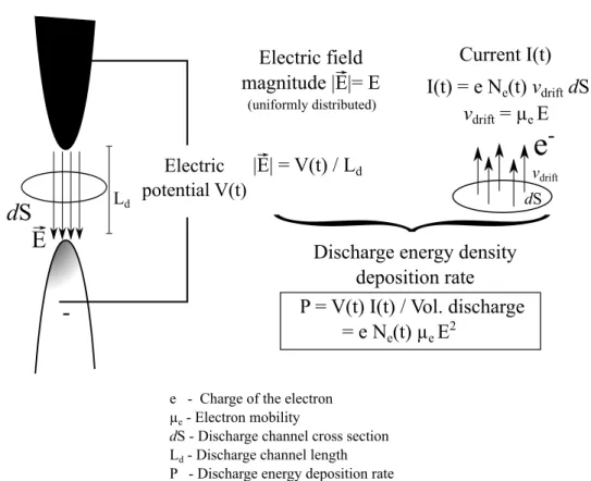
First, the discharge energy deposition rate per unit volume P (t) is added as a source term to the energy balance equation Eq. (2.3):
@(⇢e) @t + @(⇢uie) @xi = @qi @xi +@( ijui) @xi + P (t) (2.16)
By definition, the discharge energy power P (t) is computed with the applied voltage V (t) and the induced discharge current I(t) as follows:
P (t) = V (t) I(t)
Vdischarge (2.17)
where Vdischarge is the volume of the discharge channel.
Figure 2.1 shows a schematic representation of the strategy used to com-pute this discharge energy deposition rate P (t). The basic concepts are
described below:
• The electric potential difference on the electrodes induces an elec-tric field E between the electrodes. During the discharge, the spatial evolution of E can be computed by solving the Poisson’s equation along with the drift-diffusion equations for electrons, positive and negative ions. In the studies of streamer dynamics (Celestin (2008)
and Tholin (2012)) it is necessary to solve these equations in or-der to determine the streamer propagation phenomena. With typ-ical streamer velocities of about 108 cm s 1 (Babaeva and Naidis
(1997)), the characteristic time of streamer propagation in a gap with length Ld = 1 mm is about 1 ns. Therefore, in order to
ac-curately resolve the streamer phenomena, very small integration time steps are required in the computations. The importance of the streamer phase in single spark formation is discussed, for exam-ple, in Marode (1975);Babaeva and Naidis (1997); Celestin (2008);
Tholin (2012);Breden et al. (2013).
An important result in nanosecond repetitively pulsed spark condi-tions is demonstrated in Pai et al. (2010). Based on experimental results, the authors demonstrated that the electric field is uniformly distributed in the inter-electrode region and that the development of the discharge is uniform along the gap. With this result, the computation of the electric field E becomes significantly simplified. Indeed, considering that E is uniformly distributed in the gap, its temporal evolution can be calculated from the temporal evolution of V (t) as follows:
E(t) = V (t)
Ld (2.18)
where Ld is the inter-electrode distance, as represented in Fig. 2.1.
In NRP spark conditions, this model for E avoids solving the Pois-son’s equation along with drift-diffusion equations that otherwise
would be needed to derive the spatio-temporal evolution of E dur-ing the discharge.
• Another simplification in NRP discharges is that the magnetic field induced by the discharge current is negligible compared with the magnitude of the electric field E, as discussed in Celestin (2008)
and Tholin (2012).
Therefore, accordingly to Ohm’s law and assuming a negligible con-tribution of the magnetic field, the discharge current I(t) is given by:
I(t) = e Nevdrif tE dS with vdrif t= µeE (2.19)
where e is the value of the electric charge carried by the electrons (1.602 ⇥ 10 19 Cb), µ
e is the electron mobility, which varies as a
function of the reduced electric field E/N, and Ne is the electron
number density. E is the electric field which can be computed from Eq. (2.18), and dS is the cross-sectional area perpendicular to the electric field, as represented in Fig. 2.1. Fig. 2.2 shows a typical temporal evolution of the calculated discharge current from an im-posed voltage, characteristic of a single nanosecond discharge pulse, reproduced from Tholin (2012).
Following the above-described characteristics, the discharge energy depo-sition rate per unit volume P (t) is thus obtained by introducing Eqs. (2.18) and (2.19) into Eq. (2.17):
P (t) = e Ne(t)µeE(t)2 (2.20)
The discharge energy power is, therefore, dependent on the temporal evolution of the pulse voltage V (t) (in order to calculate the value of E(t)) and on the evolution of the electron number density Ne. To compute
Ne it is necessary to solve the electron balance equation along with the