Conception, implementation and evaluation of a
QoS – based architecture for an IP environment
supporting differentiated services
F Garcia1, C Chassot1, A Lozes1, M Diaz1, P Anelli2, E Lochin2 1LAAS/CNRS, 7 avenue du Colonel Roche, 31077 Toulouse cedex 04. Franceemail: fgarcia, chassot, alozes, diaz@laas.fr 2
LIP6, 8 rue du Capitaine Scott, 75015 Paris. France email: pascal.anelli, emmanuel.lochin@lip6.fr
Abstract. Research reported in this paper deals with the design of a communication architecture with guaranteed end-to-end quality of service (QoS) in an IPv6 environment providing differentiated services within a single Diff-Serv domain. The paper successively presents the design principles of the proposed architecture, the networking platform on which the architecture has been developed and the experimental measurements validating the IP level mechanisms providing the defined services. Results presented here have been obtained as part of the experiments in the national French project @IRS (Integrated Architecture of Networks and Services).
1
Introduction
Technical revolutions in computer science and telecommunications have led to the development of several new types of distributed applications: multimedia and co-operative applications, interactive simulation, etc. These new applications present challenging characteristics and constraints to network designers, such as higher bandwidths, the need for bounded delays, etc. As a result, the Internet community formed two research and development efforts (IETF1 Int-Serv [1] and Diff-Serv [2] working groups) whose goal is to develop a new generation of protocols within a revised architecture for the TCP/IP protocol suite. One of the key points of that architecture is that the new “differentiated” or “integrated” services respond to the needs of new applications. Performed within the national French project @IRS2, work presented within this article straddles this context. More precisely, it deals with the conception, the implementation and the evaluation of a communication architecture providing a guaranteed end-to-end QoS in an IPv6 differentiated services environment constituting a single Diff-Serv domain. Several other
1 IETF: Internet Engineering Task Force 2
The @IRS project (Integrated Networks and Services Architecture) is a national project of the France's RNRT (Réseau National de la Recherche en Télécommunications), whose objective is the development and experimentation of innovative Internet mechanisms and protocols within an heterogeneous telecommunications infrastructure (ATM, satellite, wireless, LAN, etc.). Initiated in December 1998, project @IRS has ended in April 2001.
works have been initiated to target the QoS problem within the Internet. Among them, let’s cite the TF-TANT activity [3] and the GEANT, TEQUILA, CADENUS, AQUILA and GCAP IST projects [4,5,6,7,8].
The article is structured as follows. Section 2 presents the architecture principles. Section 3 describes the experimental platform over which the architecture has been developed. Section 4 details the experimental scenarios for the validation of the IP QoS mechanisms providing the defined services; results of the corresponding measurements are also provided and analysed. Conclusions and future work are presented in Section 5.
2
General architecture
The following two major sections (2.1 and 2.2) successively present the architecture defined at the end-to-end level and then at the network level.
2.1 End-to-end level
The basic underlying principle that supports the proposal of the @IRS end-to-end architecture is one of many dedicated to the transport of multimedia flows [9,10,11,12]. The idea is that the traffic exchanged within a distributed application can be decomposed into several data flows each one requiring its own specific QoS (i.e. delay, reliability, order, …). That is, each application can request a specific QoS for each flow via a consistent API (Application Programming Interface) offering parameters and primitives for a diverse set of necessary services. By way of a session (see Figure 1), the application layer software is then allowed to establish one or many end-to-end communication channels, each being: (1) unicast or multicast, (2) dedicated to the transfer of a single flow of application data, and (3) able to offer a specific QoS.
IPv6 + traffic control
RSVP, … ...
Application Adaptation application / API
UDP / TCP / POC
Association transport channel / IP QoS
IP QoS system management API
Figure 1. Architecture of the end-to-end communication system
Besides the API, three other modules are defined:
− the first one provides multiple transport layer possibilities, such as TCP, UDP, or the partial-order, partial-reliable POC (Partial Order Connection [13,14]);
services at the IP layer (e.g., RSVP, RSVP light, manual configuration);
− the third one associates a given transport channel with a given IP QoS service. Two types of modifications have been defined for the applications: the translation of transport layer function calls (e.g. socket) to the new API, and the insertion of an adaptation layer managing the establishment of end-to-end QoS-based communication channels, along with translating the applications' needs into generic parameters understood by the API. Since the experimental results presented in the paper are “IP QoS” rather than “Transport QoS” oriented, we do not present the API in detail. However, we precise that the QoS specified for each end-to-end channel is expressed by the following p arameters:
− a partial order, expressed as both an intra and inter flow order since a user may want a logical synchronisation service either within each flow (e.g., logical synchronisation of two media transported within the same end-to-end channel) or between flows (e.g., logical synchronisation of voice and video);
− a partial reliability defined, for example, by a maximum number of consecutive lost packets, and/or by a maximum running percentage of lost packets;
− a maximum end-to-end transmission delay.
Although the question is pertinent, the goal of this paper is not to describe and enforce ordering relationships within channels that may lose packets to tackle synchronisation needs associated with multimedia applications, or to reduce the transit delay of application level data units. Identically, the paper does not study the usefulness of RTP based propositions. Finally, in addition to QoS parameters, an application must specify four service parameters:
− the first one characterises the traffic generated by the application sender; for this, the token bucket model is used;
− the second one designates which transport protocol to use (e.g. UDP, TCP or POC). One of the proposed future research activities is to determine if it is possible and/or efficient to have the system automatically select the transport protocol. For now, this choice must be specified by the application;
− the third one designates the IP layer's QoS management desired by the application (e.g. Best Effort service, Int-Serv Guaranteed or Controlled Load services, Diff-Serv Premium or Assured services, etc.). Here again, automatic selection is a proposed research activity outside the scope of the work presented here;
− the final parameter identifies the address, either unicast/multicast, of a set of destination application softwares.
Although the architecture is designed so as to allow several kinds of Transport protocols or IP level management systems, the architecture implemented within the project only includes UDP and TCP at the Transport level and a Diff-Serv proposition (described in section 2.2) at the IP level.
2.2 Network level
QoS functions performed at the network level can be divided in two parts: those related to the data path and those related to the control path [15]. On the data path, QoS functions are applied by routers at the packet level in order to provide different levels of service. On the control path, QoS functions concern routers configuration and act to enforce the QoS
provided. If studies performed during the @IRS project tackle the two areas (data and control paths), only the data part has been implemented and evaluated over the experimental platform. In this section, we first describe the defined services at the IP level. Then we detail the different functions required for the services implementation, with a clear separation between the control path and the data path.
2.2.1 Services
Three services have been defined at the IP level:
− GS (Guaranteed Service) - analogous to the Premium Service [16] - is used for data flows having strong constraints in both delay and reliability. Applications targeted by GS are those which do not tolerate QoS variation;
− AS (Assured Service) is appropriate for responsive flows having no strong constraints in terms of delay, but requiring a minimum average bandwidth. More precisely, a flow served in AS has to be provided with an assured bandwidth for the part of its traffic (IN packets) respecting the characterisation profile specified for the flow. Part of the traffic exceeding the characterisation (OUT - or opportunistic - packets) is conveyed in AS as far as no congestion occurs in the network on the path used by the flow;
− BE: Best Effort service offers no QoS guarantees.
Three markings have been defined to differentiate packets: EF (Expedited Forwarding), AF (Assured Forwarding) and DE (Discard Eligibility) [17,18], corresponding to the three services provided at the IP level.
2.2.2 Control path QoS functions
In order to implement the mentioned services in the testbed network (described in section 3), the two mechanisms involved in the control path are admission control and route
change protection. Note that the multicast issue is not studied in this paper.
Admission control. The admission control takes care of the acceptance of new flows in
service classes. Its decisions are taken according to the TCA1 contracted between the user domain and the service provider domain. Our proposition is different for AS and GS:
− for AS, a per flow admission control is applied at the edge of the network (core routers are not implied); this control is based on the amount of AS traffic already authorised to enter the network by the considered edge router. This gives the guarantee that at any time, the amount of in profile AS packets (IN packets) in the network will be at most the sum of the AS authorised at each edge router;
− for GS, as a delay guarantee is needed, the admission control involves all the routers on the data path (edge and core routers). As for AS, it is applied per flow, each flow being identified by the couple (flow_id field, source address).
Route change protection. This issue is raised for GS only as a route change can have a
heavy impact on the service and even results in the service not being available anymore. As it has been decided in the @IRS project that QoS and routing issues would be considered
1
TCA - Traffic Control Agreement: part of the SLA (Service Level Agreement [19]) that describes the amount of traffic a user can send to the service provider network.
separately, our solution is to use static routing only. 2.2.3 Data path QoS functions
QoS functions involved in the data path are policing, scheduling and congestion control. We first describe these three functions, then we detail their implementation within routers
input and output interfaces.
2.2.3.1 Data path functions description
Policing . Policing deals with the actions to be taken when out of profile traffic arrives in a
given service class:
− for AS, the action is to mark the out of profile packets with a higher drop precedence than for the IN traffic. OUT packets are called opportunistic packets because they are processed like the other IN AS packets, as far as no congestion occurs in the network. If congestion occurs, the congestion control described here after is applied. Targeted applications are those whose traffic is elastic, that is with a variable profile (a minimum still being assured);
− for GS, as a guarantee exists, we must be sure that enough resources are available; therefore the amount of GS traffic in the network must be strictly controlled. To enforce this, the chosen policing method is to shape the traffic at the edge router and to drop out of profile GS packets.
Scheduling . Once again, the scheduling is different for AS and GS packets:
− GS scheduling is implemented by a Priority Queuing (PQ) mechanism. This choice is due to the fact that a PQ based scheduler adds the smallest delay to the packet forwarding due to packetisation effect;
− the remaining bandwidth is shared by a Weighted Fair Queuing (WFQ) between AS and BE traffic. This ensures that there will not be service denial for BE.
Congestion control. The congestion control issue is essential for QoS services, as a
congestion can prevent the network from offering the contracted QoS to a flow:
− GS traffic does not need congestion control as it benefits from a priority queuing ensuring that all its packets are served up to the maximal capacity of a given router. Associated with a strong policing (drop of out of profile packets) at the network boundary, this guarantees that no congestion will occur in GS queues;
− for AS, as opportunistic traffic is authorised to be sent in the network, the amount of AS packets in any router can’t be known a priori. Therefore, a drop precedence system has been implemented; it allows the drop of opportunistic packets as soon as a congestion is about to occur in an AS queue. A Partial Buffer Sharing (PBS) has been chosen on the AS queues rather than a Random Early Discard (RED) method. This choice comes from recent studies which show that simple systems such as PBS avoid the queue length oscillation problems raised by RED [20,21]. Let us now look at the implementation of these functions over the @IRS platform through the input interface of the first router (called edge router as opposed to core routers) and the
2.2.3.2 Data path functions implementation
Input interface of edge router. This interface is the first encountered by a packet when it
enters the network. Its logical structure is shown in Figure 2.
IPv6 packets GS AS inside-profile outside-profile EF AF Reject Meter shaper Dropper MF Classi fier Meter Marker inside-profile outside-profile DE BE
Figure 2. Input interface structure
This interface is in charge of:
− packets classification, which is based on information from the IPv6 header (source address and flow_id); this is done through a MultiField Classifier;
− measuring AS and GS flows to determine whether they are in or out of profile;
− shaping GS packets and dropping them if necessary;
− marking AS and GS packets with the appropriate Diff-Serv CodePoint (DSCP)
− marking AS packets with the precedence due to their being in or out profile;
− marking BE packets to prevent them from entering the network with the DSCP of another service class.
Output interface of all routers. In the Diff-Serv model, all routers must implement a set of
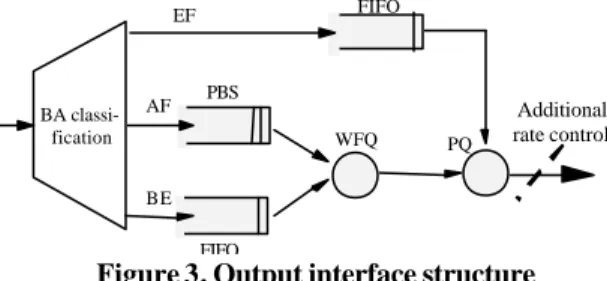
forwarding behaviours called Per Hop Behaviour (PHB). In the @IRS architecture, these behaviours are implemented through scheduling and AS congestion control as described in section (2.2.3.1). They are integrated in the output interface of each router (Figure 3).
WFQ PQ BA classi-fication EF AF BE FIFO PBS FIFO Additional rate control
Figure 3. Output interface structure
Two additional points must be noted: the Behaviour Aggregate classifier which classifies packets according to their DSCP, and the rate control at the output of core routers. As it will appear more clearly in the next section, this rate control is necessary to avoid congestion at the ATM level. Indeed, congestion at the ATM level is due to the fact that ATM Virtual
ATM cards of the routers. Combined with the limited buffer size in the ATM switches, this could create ATM cell losses when the throughput of the router is not controlled.
3
Experimental platform
The testing network environment used for applications of the project is shown in Figure 4
ISP R b RENATER2 Edge router R b Rc R b Rc Rc R b Rc Site 1 Site 2 Site 4 Site 3 Host Core router
Figure 4. Experimental platform
Local equipment is connected by edge routers (Rb) to an Internet Service Provider (ISP)
represented by the national ATM RENATER 2 platform. Four core routers (Rc) are
introduced within the ISP; physically, they are located in the local platforms, but logically they are part of the ISP. By means of its edge router, each site is provided with an access point to the ISP (Rb). This access point is characterised by a statically established traffic
contract called Service Level Agreement (SLA) [19]. For each service, the SLA consists of:
− classification and packet (re)marking rules;
− a sending traffic profile called Traffic Conditioning Agreement (TCA) [19] (for @IRS, the model chosen was the Token Bucket);
− actions the network has to perform when the application violates its traffic profile. It is the edge router’s responsibility to implement the SLA as it introduces application flows within the ISP. All the ATM VPs offer a 1Mbit/s Constant Bit Rate (CBR) service.
4
Experimental scenarios and measurements
The purpose of the experimental scenarios described in this section is to validate the IP mechanisms developed to provide a slightly degraded QoS for AS flows and an excellent QoS for GS flows when the network load is increasing.
4.1 Studied cases
Two cases have been considered:
− case 1: the edge router is not in state of congestion and the AS (respectively GS) flow respects its traffic profile. This case is the reference one;
− case 2: the edge router is now in state of congestion and the AS (resp. GS) flow still respects its traffic profile; the congestion is due to BE traffic. Here, we want to study the behaviour of the AS (resp. GS) flow when the network is overloaded.
4.2 Tools
The software tool used for the experiments is a traffic generator (named Debit6) developed by LIP6 and LAAS. Debit6 is able to:
− send/receive UDP/IPv6 flows under Free BDS or Window NT operating system;
− send traffic respecting a token bucket type-like profile;
− measure throughput and loss rate for a given experiment session;
− measure transit delay for each packet.
4.3 QoS validation
4.3.1 Experiment configuration
Measurements have been realised between LAAS (Toulouse) and LIP6 (Paris) over the IPv6 inter-network environment illustrated on Figure 5.
Rb X Rc RENATER 2 LAAS (Toulouse) Rb X Rc LIP6 (Paris) BSD BSD
ATM national platform AS/GS BE AS/GS ATM switch ISP ATM switch BSDexo Ethernet 100 Mbits/s
Figure 5. Inter-network environment
Bandwidth of the link connecting LAAS (resp. LIP6) to the ISP (via an ATM VP) is such that the maximal throughput provided at the UDP level is 107 Kbytes/s. In the following of the paper, we use the term link bandwidth to refer to this throughput.
4.3.1.1 Hypothesis and measured parameters.
Edge and core routers have been configured with the following hypothesis:
− the maximal amount of GS traffic that can be generated by the edge router (in average) has been fixed to 20 Kbytes/s, i.e. about 20% of the link bandwidth;
− the maximal amount of AS traffic that can be generated by the edge router (in average) has been fixed to 40 Kbytes/s, i.e. about 40% of the link bandwidth;
− the rate control applied by the core router is 107 Kbytes/s (i.e. the link bandwidth);
− weights associated to the AS and BE packet scheduling within the WFQ mechanism are respectively 0.8 and 0.2.
Measured parameters are the loss rate, the transit delay and the throughput; more precisely:
− the loss rate corresponds to the ratio between the number of not received packets and the number of sent packets for the complete experiment session;
− minimal, maximal and average values of the transit delay are calculated for the complete experiment session (about 300 seconds);
− the throughput is measured both at the sending and receiving side and corresponds to the number of user data bytes sent or received for the complete experiment session divided by the communication duration (about 300 seconds).
Note that hosts are synchronised by means of NTP (Network Time Protocol), inducing a +/-5 milliseconds (ms) uncertainty on the transit delay measurements.
4.3.1.2 Measurements specification.
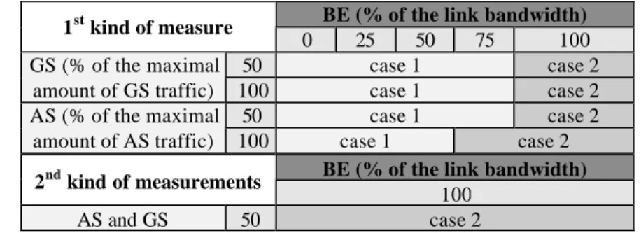
Two kinds of measurements have been defined (see Table 1). In both cases, AS and GS flows have to respect their traffic profile and all flows (GS, AS and BE) are generated by bursts of 1 UDP packet whose size is 1024 bytes. The inter-packet delay is the variable parameter used to change the throughput of the generated flows.
BE (% of the link bandwidth) 1st kind of measure
0 25 50 75 100
50 case 1 case 2
GS (% of the maximal
amount of GS traffic) 100 case 1 case 2
50 case 1 case 2
AS (% of the maximal
amount of AS traffic) 100 case 1 case 2
BE (% of the link bandwidth) 2nd kind of measurements
100
AS and GS 50 case 2
Table 1. QoS measurements specification (case 1 = no congestion ; case 2 = congestion)
The first kind of measurements is aimed at validating the protection of an AS (resp. a GS) flow in presence of a BE flow whose load is increased from 0% to 100% of the link bandwidth. AS and GS flows are not generated together. For these measurements:
− the BE flow is sent from the BSDexo PC (LAAS); values of its mean rate are
successively 0%, 25%, 50%, 75% and 100% of the link bandwidth;
− AS and GS flows are transmitted using Debit6 from LAAS BSD PC to LIP6 BSD PC; two cases are considered:
• a single AS (resp. GS) flow is generated with a mean rate corresponding to 50% of the maximal amount allowed by the edge router to AS (resp. GS) traffic, i.e. 20 Kbytes/s (resp. 10 Kbytes/s);
• a single AS (resp. GS) flow is generated with a mean rate corresponding to 100% of the maximal amount, i.e. 40 Kbytes/s (resp. 20 Kbytes/s).
The second kind of measurements is aimed at validating the protection of an AS flow and a GS flow generated together, in presence of a BE flow whose load corresponds to the totality of the link bandwidth (100%). For these measurements:
− the BE flow is sent from the BSDexo PC (LAAS); its mean rate is 107 Kbytes/s ;
− AS and GS flows are transmitted using Debit6 from LAAS BSD PC to LIP6 BSD PC, each one with a mean rate corresponding to 50% of the maximal amount provided by the edge router (i.e. 20 Kbytes/s for AS and 10 Kbytes/s for GS).
4.3.2 Results and analysis
For the first kind of measurements, due to space limitation, only the results for 100% of AS (respectively GS) are exposed in this section.
Protection of the AS flows (vs. BE). Results of the measurements are exposed in Table 2.
These results conform to the excepted ones. When the network is not in state of congestion (first three columns), one can conclude that:
− the average transit delay is almost constant (less than 1 ms gap);
− the loss rate is almost null;
− the receiving throughput is almost the same as the sending one;
− the maximum delay is not guaranteed.
Note that the second and third points are compliant to the expectations as we only consider in-profile traffic; measurements with out of profile traffic would show a receiving throughput inferior to the sending throughput (and a loss rate higher than 0)
When the network is in state of congestion, one can see that the transit delay value is slightly increased, which again is correct for the expected service.
BE (% of the link bandwidth)
AS – 100% 0% 25% 50% 75% 100% - min 0.019 0.019 0.019 0.019 0.019 - max 0.045 0.032 0.030 0.033 0.036 Transit delay (s) - average 0.020 0.021 0.021 0.024 0.024 - emission 40765 40963 40964 40963 40964 Throughput (bytes/s) - reception 40761 40963 40963 40963 40963 Loss rate (%) 0.0 0.0 0.0 0.0 0.0 Table 2. AS - 100% vs. BE
Protection of the GS flows (vs. BE). Results of the measurements are exposed in Table 3.
These results are similar to those exposed for the AS flows, the main difference being that the maximum delay for GS packets seems slightly lower than the maximum for AS packets. This is normal as we only compare AS vs. BE and GS vs. BE; indeed, in both cases, the flow that benefits from QoS goes through the network nearly as quickly as it can.
BE (% of the link bandwidth)
GS – 100% 0% 25% 50% 75% 100% - min 0.018 0.019 0.019 0.019 0.019 - max 0.024 0.029 0.031 0.032 0.033 Transit delay (s) - average 0.019 0.020 0.022 0.023 0.025 - emission 18289 18289 18290 18289 18289 Throughput (bytes/s) - reception 18289 18289 18289 18289 18289 Loss rate (%) 0.0 0.0 0.0 0.0 0.0 Table 3. GS - 100% vs. BE
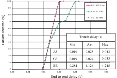
Protection of the AS and GS flows (vs. BE). Results of the measurements are exposed in
Figure 6, which presents the % of packets received with a delay less than or equal to the value denoted on the x-axis. The difference between AS and GS is now apparent for the
maximum delay which is much higher for AS. Moreover, one can observe that the transit delay of the AS packets is more widely spread than the GS one. Note that the BE curve is not shown because it is out of the scale of the graphic.
0 1 0 2 0 3 0 4 0 5 0 6 0 7 0 8 0 9 0 100 0,00 0,01 0,02 0,03 0,04 0,05 0,06
End to end delay (s)
Packets received (%)
BE ( 100 Ko/s)
AS ( 20 Ko/s)
GS ( 10 Ko/s)
Min Moy Max
AS 0.019 0.025 0.043
GS 0.019 0.024 0.033
BE 0.284 4.126 4.245
Transit delay (s)
Figure 6. AS - 50% vs. GS - 50% vs. BE - 100%
5
Conclusions and future work
Work presented in this paper has been realised within the @IRS French project. It consists in the conception, the implementation and the validation of a communication architecture supporting differentiated IP level services as well as a per flow end-to-end QoS. The proposed architecture has been exposed in section 2; the network over which it is deployed has been described in section 3; finally, an experimental evaluation of the QoS provided by the defined IP services (GS, AS and BE) has been exposed in section 4.
Several conclusions may be stated:
− the first one is that a differentiated services architecture may be easily deployed over a VPN (Virtual Private Network )-like environment such as the one described;
− the second conclusion is that if experimental results correspond to the expected ones (as far as the GS, AS and BE services are concerned), the effect of the IP level parameters (router’s queue length, WFQ weights, PBS threshold, …) appears to be a crucial point in the implementation of the services. For instance, size of the AS queues has an influence on the offered service, short queues inducing a delay priority, longer queues inducing a reliability priority. In the same way, the PBS threshold defines the way the network reacts to the out of profile traffic, thus providing a service more or less adapted to applications needing a base assurance and willing to use additional available resources.
Three major perspectives of this work are currently under development:
− the first one is to extend the experimentations exposed in this paper so as to evaluate the IP QoS when several routers are overloaded with best effort traffic;
− the second one is to evaluate the QoS at the application level when several flows requiring a same class of service are generated;
− finally, it is our purpose to formalise the semantic of guarantee associated with the QoS parameters and to develop a mechanism allowing the application to be dispensed from the explicit choice of the Transport and IP services to be used. Finally, a long term perspective of this work is the extension to a multi-domain environment, by using for example bandwidth brokering.
REFERENCES
1. IETF: IntServ WG: http://www.ietf.org/html.charters/intserv-charter.html
2. IETF: DiffServ WG: http://www.ietf.org/html.charters/diffserv-charter.html
3. TF-TANT: http://www.dante.net/tf-tant
4. Campanella, M., Ferrari, T., et al: Specification and implementation plan for a Premium IP service. http://www.dante.org.uk/tf-ngn/GEA-01-032.pdf (2001). 5. TEQUILLA: http://www.ist-tequila.org
6. CADENUS: http://www.cadenus.org
7. AQUILA: http://www-st.inf.tu-dresden.de/aquila
8. GCAP: http://www.laas.fr/GCAP/
9. Campbell, A., Coulson, G., Hutchinson, D.: A quality of service architecture. ACM Computer Communication Review (1994).
10. Nahrstedt, K., Smith, J.: Design, Implementation and experiences of the OMEGA end-point architecture. IEEE JSAC, vol.14 (1996).
11. Gopalakrishna, G., Parulkar, G.: A framework for QoS guarantees for multimedia applications within end system. GI Jahrestagung. Zurich (1995).
12. Chassot, C, Diaz, M, Lozes, A.: From the partial order concept to partial order multimedia connection. Journal for High Speed Networks, vol. 5, n°2 (1996). 13. Amer,P., Chassot, C., Connolly, C., Conrad,P., Diaz, M .: Partial Order Transport
Service for MM and other Appli. IEEE/ACM Trans. on Neting, vol.2, n°5 (1994). 14. Connolly, T., Amer, P., et al.: An Extention to TCP: Partial Ord. Serv. RFC 1693. 15. Zhao W, Olshefski D, Schulzrinne H.: Internet Quality of Service: an Overview.
Technical Report CUCS-003-00. http://www.cs.columbia.edu/~hgs/netbib/ (2000). 16. Nichols, K., Jacobson, V., Zhang, L.: A Two-bit Differentiated Services
Architecture for the Internet. November 1997.
17. Heinanhen, J., Baker, F., Weiss, W., and al.: An Assured Fwding PHB. RFC 2597. 18. Jacobson, V., Nichols, K., Poduri, K.: An Expedited Forwarding PHB. RFC 2598. 19. Blake, S., Black, D., Carlson, M.: An Arch. for Differentiated Services. RFC 2475. 20. Bonald, T., May, M., Bolot, J.: Analytic Evaluation of RED Performance.
Proceedings INFOCOM’2000, Tel Aviv (2000).
21. Ziegler, T., Fdida, S., Brandauer, C.: Stability Criteria of RED with TCP Traffic. Internal report. http://www.newmedia.at/~tziegler/red_stab.pdf. (2000).