HAL Id: tel-01419342
https://tel.archives-ouvertes.fr/tel-01419342v2
Submitted on 28 Dec 2016HAL is a multi-disciplinary open access
archive for the deposit and dissemination of sci-entific research documents, whether they are pub-lished or not. The documents may come from teaching and research institutions in France or abroad, or from public or private research centers.
L’archive ouverte pluridisciplinaire HAL, est destinée au dépôt et à la diffusion de documents scientifiques de niveau recherche, publiés ou non, émanant des établissements d’enseignement et de recherche français ou étrangers, des laboratoires publics ou privés.
Copyright
fabrication of the Supporting System for the CLIC
Two-Beam Module
Nikolaos Gazis
To cite this version:
Nikolaos Gazis. Engineering study, development and prototype fabrication of the Supporting System for the CLIC Two-Beam Module . High Energy Physics - Experiment [hep-ex]. UNIVERSITE DE GRENOBLE, 2016. English. �tel-01419342v2�
THÈSE
Pour obtenir le grade de
DOCTEUR DE LA COMMUNAUTÉ UNIVERSITÉ
GRENOBLE ALPES
Spécialité : PHYSIQUE/ PHYSIQUE APLIQUEE
Arrêté ministériel : 17 Juin 2016
Présentée par
Nikolaos GAZIS
Thèse dirigée par Steinar STAPNES et codirigée par Jean-Marie DE CONTO préparée au sein du
CERN - Conseil Européen pour la Recherche Nucléaire
dans l'École Doctorale Physique (Grenoble)
Etude d’ingénierie, développement et
fabrication prototype du système de
support pour le module CLIC de
double faisceau
Thèse soutenue publiquement le 28 Septembre 2019, devant le jury composé de :
M. Jean KARYOTAKIS
Président du jury,
DIRECTEUR DE RECHERCHE CNRS DELAGATION ALPES
M. Theodoros ALEXOPOULOS
Rapporteur du jury,
PROFESSEUR UNIV.POLYTECHNIQUE NATIONALE ATHENES
M. Pierre Richard DAHOO
Rapporteur du jury,
PROFESSEUR UNIVERSITE DE VERSAILLES – UVSQ
M. Jean-Marie DE CONTO
Membre du jury,
PROFESSEUR UNIVERSITE GRENOBLE ALPES
MME Andrea JEREMIE
Membre du jury,
INGENIEUR DE RECHERCHE CNRS DELEGATION ALPES
M. Constantin MEIS
Membre du jury,
PROFESSEUR CEA DE SACLAY
M. Patrick PUZOT
Membre du jury,
UNIVERSITÈ GRENOBLE ALPES
Nikolaos GAZIS
Mechanical and Aeronautics Engineer
ENGINEERING STUDY, DEVELOPMENT AND
PROTOTYPE FABRICATION OF THE SUPPORTING
SYSTEM FOR THE CLIC TWO-BEAM MODULE
PhD Thesis
Index
Introduction ...xiii resume de l’etude ...xiii CONCLUSIONS ET PERSPECTIVES ... xv
Chapter 1.
CERN AND THE CLIC STUDY ... 1.18
1.1 Introduction to CERN – The European Organization for Nuclear Research 1.19
1.2 The research program of CERN ... 1.20 1.3 CLIC Study overview and key issues ... 1.22 1.4 The CLIC Two-Beam acceleration scheme ... 1.23 1.5 The CLIC Two-Beam Modules ... 1.23 1.5.1 Description and types of Modules ... 1.23 1.5.2 Technical systems ... 1.25 RF System ... 1.25 1.5.2.1 Cooling System ... 1.26 1.5.2.2 Vacuum System ... 1.26 1.5.2.3
Magnet System and magnet powering system ... 1.26 1.5.2.4 Supporting System ... 1.27 1.5.2.5 Alignment System ... 1.27 1.5.2.6 Stabilization System ... 1.28 1.5.2.7 Beam instrumentation ... 1.28 1.5.2.8
Handling and transport ... 1.29 1.5.2.9
Chapter 2.
THE SUPPORTING SYSTEM OF THE CLIC
TWO-BEAM MODULE ... 2.31
2.1 Description of the CLIC supporting and positioning system ... 2.32 2.2 Technical specifications ... 2.33 2.2.1 Girder ... 2.34 2.2.2 V-shaped supports ... 2.36 2.2.3 Cradles and alignment sensors ... 2.38 2.2.4 Articulation Points ... 2.39 2.2.5 Actuators and active alignment ... 2.40
Chapter 3.
ENGINEERING DESIGN OF THE CLIC
SUPPORTING SYSTEM ... 3.43
3.1 Description of the study ... 3.44 3.1.1 Weight estimation of the Module components ... 3.44 3.1.2 Boundary conditions of the supporting system ... 3.46 3.1.3 Operational conditions of the supporting system ... 3.49 3.2 Configuration study and FEA models ... 3.50 3.2.1 Introduction ... 3.50 3.2.2 Girder configuration study ... 3.50
3.2.3 V-shaped support configuration study ... 3.53 3.2.4 Summary for the baseline and alternative configurations of the
supporting system ... 3.56 3.3 Material study and FEA models ... 3.57 3.3.1 Introduction ... 3.57 3.3.2 Girder material study ... 3.58 3.3.3 V-shaped support material study ... 3.60 3.3.4 Summary for the baseline and alternative materials for the supporting system 3.62
Chapter 4.
FABRICATION OF THE CLIC SUPPORTING
SYSTEM
4.63
4.1 Introduction to the fabrication strategy ... 4.64 4.2 Key parameters for the fabrication ... 4.66 4.2.1 Dimensional tolerances and industrial applications ... 4.66 4.2.2 Transportation and handling methodology ... 4.67 4.2.3 Installation and interchangeability for the components of the Module supporting systems ... 4.69 4.3 Fabrication of the supporting systems for the CLIC Two-Beam Module .. 4.70 4.3.1 Fabrication of peripheral components of the supporting system ... 4.71 4.3.2 Supporting systems for the LAB ... 4.72 Case A (Boostec SiC) ... 4.73 4.3.2.1
Case B (Micro-Controle SiC) ... 4.77 4.3.2.2
Case C (Epument 145/B) ... 4.80 4.3.2.3
Case D (Boostec SiC) ... 4.83 4.3.2.4
4.3.3 Supporting system in CLEX ... 4.84 Case E (Firm consortium of ZTS and Boostec) ... 4.85 4.3.3.1
4.3.4 Fabrication results ... 4.85
Chapter 5.
QUALIFICATION OF THE CLIC SUPPORTING
SYSTEM
5.87
5.1 Introduction to the qualification measurements ... 5.88 5.2 Qualification (at the manufacturing facilities) ... 5.89 5.2.1 Case A (Boostec SiC) ... 5.89 5.2.2 Case B (Micro-Controle SiC) ... 5.91 5.2.3 Case C (Epument 145/B) ... 5.93 5.3 Qualification measurements (at CERN) ... 5.96 5.3.1 Case A (Boostec SiC) ... 5.96 5.3.2 Case B (Micro-Controle SiC) ... 5.97 5.3.3 Case C (Epument 145/B) ... 5.98 5.4 Modal measurements ... 5.98 5.5 Qualification measurements outcome ... 5.101
Chapter 6.
QUALIFICATION OF MATERIALS FOR THE
CLIC SUPPORTING SYSTEM ... 6.102
6.2 Introduction to the irradiation testing ... 6.103 6.3 The irradiation testing ... 6.106 To investigate the mechanical behavior and possible changes of the supporting system structural materials, due to the radioactive background, dedicated irradiation experiments are required for the supporting system materials with neutron beams, based on the latest available simulations of the radiation
background due to beam losses. After the neutron bombardment, the samples of these materials are compared with reference samples of intact material to control and examine their corresponding mechanical properties, as described in chapter 6.7. ... 6.106
6.3.1 Irradiation testing setup: neutron beam interaction ... 6.106 6.3.2 The neutron beam sources ... 6.107 6.4 The NCSR “Demokritos” Tandem accelerator neutron beams ... 6.108 6.4.1 The Tandem accelerator facility ... 6.108 6.4.2 The neutron beams ... 6.109 6.4.3 The neutron beam angular characteristics ... 6.111 6.5 Material samples for the irradiation tests ... 6.111 6.6 The neutron beam irradiation test and monitoring ... 6.113 6.7 The radiation test data analysis ... 6.114 6.7.1 The gamma ray spectrometry ... 6.114 6.7.2 The X-ray fluorescence spectroscopy ... 6.114 6.7.3 Activation foils ... 6.114 6.7.4 Activation calculations ... 6.116 6.7.5 Data analysis results ... 6.116 6.7.6 Activation calculations ... 6.117 6.8 Introduction to the mechanical testing ... 6.118 6.9 Description of the MECHANICAL strength tests ... 6.119 6.10 Experimental procedure for the UCT (Uniaxial Compression Test) ... 6.120 6.11 Data analysis and discusssion for the UCT METHOD ... 6.123 6.12 Description of the three-point bending (3PB) testing ... 6.127 6.13 Experimental procedure for the three-point bending testing ... 6.127 6.14 Data analysis and discussion for the three-point bending testing ... 6.131 6.15 DESCRIPTION OF THE BRAZILIAN DISC tests ... 6.131
6.16 EXPERIMENTAL PROCEDURE FOR THE Brazilian DISC TESTING
6.132
6.17 ANALYSIS RESULTS AND CONCLUSIONS OF THE BRAZILIAN
DISC TESTS ... 6.138 6.18 Summary and conclusions of testing ... 6.139 6.18.1 Irradiation testing ... 6.139 6.18.2 Mechanical testing ... 6.140 UCT conclusions ... 6.140 6.18.2.1
Three-point bending conclusions ... 6.141 6.18.2.2
7.1 Summary of the study ... 7.143 7.2 Conclusions and outlook ... 7.145
List of Figures
Figure 1-1: Map of Europe with the 20 member states of CERN ... 1.19 Figure 1-2: The accelerator complex of CERN ... 1.20 Figure 1-3: A Higgs Boson Event: A Higgs boson plus a jet in the opposite direction where the Higgs boson decays to two Z bosons and one Z boson decaying to e+e- and
the other to μ+μ- ... 1.21
Figure 1-4: The CLIC layout at 3 TeV ... 1.22 Figure 1-5: The CLIC Two-Beam acceleration scheme ... 1.23 Figure 1-6: Schematic layout of CLIC Type-0 Module ... 1.24 Figure 1-7: Schematic layout of CLIC Modules with MBQs ... 1.24 Figure 1-8: 3D view of the CLIC Two-Beam Module (Type 1) ... 1.25 Figure 1-9: Tunnel handling and installation representation for the CLIC Two-Beam Module ... 1.30 Figure 2-1: Supporting system concept: "Snake System" ... 2.32 Figure 2-2: CLIC Two-Beam Module (Type-0) supporting system ... 2.32 Figure 2-3: 3D simulation of Modules in series in the CLIC tunnel ... 2.34 Figure 2-4: Schematic representation of the CLIC Module girder (Type-0)... 2.34 Figure 2-5: Schematic representation of the clearances on the girder for the clamping of the cradle ... 2.36 Figure 2-6: Schematic representation of a typical V-shaped support ... 2.37 Figure 2-7: Schematic representation of the tolerance field for the beam axis of the RF components ... 2.37 Figure 2-8: Schematic representation of the cradles assembled on a girder (MB Type-1) ... 2.38 Figure 2-9: Schematic representation of the cradle assembly including actuators and alignment sensors ... 2.39 Figure 2-10: Conceptual design of the articulation point ... 2.39 Figure 2-11: Coordinate System ... 2.40 Figure 2-12: Schematic representation of a master cradle assembly with three (3) high resolution linear actuators ... 2.40 Figure 2-13: Schematic representation of the alignment tolerance between adjacent girders ... 2.41 Figure 2-14: Schematic representation of the master-slave sequence for the MB .. 2.41 Figure 2-15: Interconnected girder extremities for the active alignment... 2.42 Figure 3-1: Typical CLIC Module Type-0 supporting system for the MB (July 2008) . 3.44 Figure 3-2: CLIC Module Type-1 (July 2009) ... 3.45 Figure 3-3: Schematic representation of the Module components ... 3.45 Figure 3-4: Simulation results of deformation (in μm) under thermal and vacuum testing conditions and gravity applied ... 3.46 Figure 3-5: CLIC coordination system ... 3.47 Figure 3-6: Boundary conditions of two Modules in series Types 1-0... 3.47 Figure 3-7: Preliminary U-clamp design ... 3.48 Figure 3-8: Schematic representation of girder simulated cross-sections ... 3.50
Figure 3-9: Alternative girder cross-section ... 3.51 Figure 3-10: Optimized alternative girder cross-section ... 3.52 Figure 3-11: Typical Strain-Stresses curves for industrial materials (SiC and StSt) ... 3.52 Figure 3-12: Deformation simulation results for the girder ... 3.53 Figure 3-13: Preliminary space reservation for the V-shaped supports ... 3.54 Figure 3-14: V-shaped support models for the MB and DB ... 3.55 Figure 3-15: Deformation simulation results for the V-shaped supports ... 3.55 Figure 3-16: Design of the sub-assembly of girders and V-shaped support with their micrometric fabrication tolerances (extracted from the production drawings) ... 3.56 Figure 3-17: Girder Cross-sections used for the material study ... 3.58 Figure 3-18: Indicative preliminary designs of the V-shaped support ... 3.61 Figure 3-19: Non-integrated V-shaped supports (StSt) on Epument (145/B) girder 3.62 Figure 4-1: Modules in the LAB (sequence of Types 1-0-0-4) ... 4.65 Figure 4-2: Indicative Module Type-0 in CLEX ... 4.65 Figure 4-3: Rough external volume of the supporting systems, part of the fabrication specifications, provided to the manufacturing firms. The delivered supporting systems for the Modules were tested to have a volume compatibility of 100% with it. ... 4.67 Figure 4-4: Components of the prototype supporting system for the CLIC Module Type-0 (LAB) ... 4.68 Figure 4-5: a) Assembled CLIC Module with its transportation frame, b)
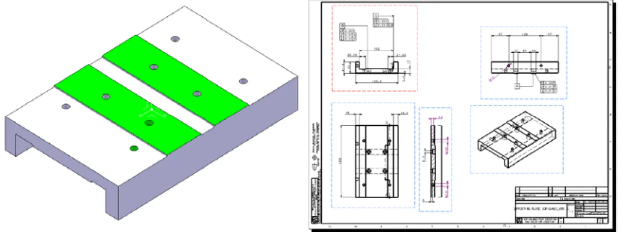
Transportation frame assembled on the supporting system of the CLIC Module (lifting hooks in red) ... 4.68 Figure 4-6: CLIC Module installation sequence (in steps) ... 4.69 Figure 4-7: Illustration of the girder assembly/disassembly strategy ... 4.70 Figure 4-8: Prototype supporting systems for the LAB Modules ... 4.71 Figure 4-9: Illustration of the series production supporting systems for the CLEX Modules ... 4.71 Figure 4-10: Schematic representation and fabrication drawing for the supporting plate of the DBQ ... 4.72 Figure 4-11: a) SiC raw material in grain, b) SiC powder and SiC monolithic
component produced by sintering, c) Different phases of fabrication, d) Grinding of SiC component, e) SiC part during fabrication step, f) SiC parts of Herschel telescope in final assembly ... 4.73 Figure 4-12: DB Type-0 girder with integrated V-shaped supports for the LAB
configuration ... 4.74 Figure 4-13: Monolithic parts of SiC ... 4.74 Figure 4-14:Case A monolithic parts made of SiC ... 4.75 Figure 4-15:Girder metal plates for cradle fixation ... 4.75 Figure 4-16: U-clamps for the prototype supporting system of the DB Type-0 Module (LAB) ... 4.76 Figure 4-17: a) SiC standard rectangular tubes, b) Preliminary alignment strategy of SiC glued V-shaped supports, c) SiC girder, glued V-shaped supports and cradles ready for final precise machining, d) Motorized station including actuators and articulation point. ... 4.78 Figure 4-18: a) Disassembled interlink of two girders ... 4.78 Figure 4-19: Delivery and assembly sequence of the supporting system for Case B 4.79 Figure 4-20: Pre-stress girder of Case B ... 4.79
Figure 4-21: U-clamps for the prototype supporting system of the MB Type-0 Module (LAB) ... 4.80 Figure 4-22: PSI girder, b) Supporting structure for milling machine, c) Girder for cutting-tool distributor machine. ... 4.81 Figure 4-23: Epument girder mould (StSt) ... 4.82 Figure 4-24: V-shaped supports (StSt) with integrated U-clamps (DB Type-1)... 4.83 Figure 4-25: Final precise machining of the V-shaped supports (StSt) under dummy loads for the fabrication Case C ... 4.83 Figure 4-26: Space reservation for the Case D girder with integrated V-shaped
supports (SiC) ... 4.84 Figure 4-27: CLEX configuration of Modules (Types 0-0-1 in series) ... 4.85 Figure 5-1: Different types of fiducials: a)Laser target (fiducial), b) Optical target (fiducial for micro-triangulation), c) Optical prism with its holder (fiducial with its support), d) Holder for spherical prism (fiducial support), e) Spherical prism (fiducial) ... 5.88 Figure 5-2: References surfaces for the Case A girders with integrated V-shaped supports (SiC) ... 5.90 Figure 5-3: References surfaces for the Case B supporting systems (SiC) ... 5.92 Figure 5-4: References surfaces for the Case C girders (Epument 145/B) ... 5.94 Figure 5-5: Shimming operation: a) Extraction from the fabrication drawing
(CLIATLSS0065), b) Fiducialised Epument girder with shims (under the V-shaped supports) installed during the geometrical control. ... 5.95 Figure 5-6: a) Representation of the CMM model during dimensional control, b)Case B girder loaded with dummy weights during CMM measurements. ... 5.97 Figure 5-7: Representation of the CMM model of Case C during the dimensional control ... 5.98 Figure 5-8: Setups for the modal measurements of the Module supporting system ... 5.100 Figure 5-9: First (1st) modes of: a) MB loaded girder, b) MB V-shaped support, c) DB loaded girder, d) DB V-shaped support. ... 5.100 Figure 5-10: Alignment plates under the cradles creating rigid body modes ... 5.101 Figure 6-1: a) Main Beam (ΜΒ) and Drive Beam (DB). The continuous lines define the geometrical limits of the simulations, b) Spatial distribution of the absorbed dose from the 0.01% of the main beam losses at 9.0 GeV c) Spatial distribution of the absorbed dose from 1% max drive beam losses at 2.4 GeV ... 6.105 Figure 6-2: Screenshots from FLUCA simulation: a) Radiation background in the future CLIC tunnel presented as cross section vs particle energy, b) Spatial distribution of the radiation background in the future CLIC tunnel, c) The detailed spatial distribution of the CLIC radiation background zoomed at the two-beam area. ... 6.106
Figure 6-3: Material penetration properties of neutrons in comparison with other particles ... 6.107
Figure 6-4: Halls of the Tandem laboratory: beam target rooms (GREEN and RED), 1) Power supplies of the sources, 2) Sputter source, 3) Duoplasmatron source, 4)
Generator tank, 5) Analysing magnet, 6) Switching magnet. ... 6.108 Figure 6-5: A schematic representation of the complete Tandem accelerator machine frames its real photograph: The machine and the 90º analyser magnet for the beam experimental line selection via the switcher magnet. ... 6.109
Figure 6-6: The Tandem accelerator gas target area (RED Hall): a, b, c, d) Assembly configurations of the neutron beam target area, e, f) Multiple Foil technique for the characterization of the neutron beam. ... 6.110 Figure 6-7: The Tandem accelerator RED Hall: Different views of the gas-target assembly with the foil holders for monitoring the neutron beam ... 6.111 Figure 6-8: a) The measured neutron flux versus the angle of emission, b) The neutron energy drop versus the angle of emission for the neutrons produced by the
2H(2H,n)3He reaction [6]. ... 6.111 Figure 6-9: a, b) Specimen before the irradiation sessions, c, d) Support configuration for the specimen assembly. ... 6.113 Figure 6-10: a, b, c, d) Multiple foils setup with Plexiglas sandwiched specimens (for the heat decay), e, f) A dose of 40-50 μSV/h is estimated near the target area for an assembly time of ≤ 10 min. ... 6.113 Figure 6-11: High purity Germanium detector measurements (post-irradiation
measurements) for the radio-activation and characterization of the specimen .... 6.114 Figure 6-12: The specific activity of SiC, as a function of post-irradiation time and dominant nuclides ... 6.118 Figure 6-13: Simple compression testing specimen: a) SiC sample during preliminary dimensional check, b) SiC sample before the simple compression test, c) Epument 145/B sample before the simple compression test. ... 6.120 Figure 6-14: UCT specimen ... 6.121 Figure 6-15: Specimen tested with UCT: a, b, c) Epument 145/B samples after UCT, d) SiC sample before UCT, e, f, g) SiC samples after UCT. ... 6.122 Figure 6-16: Graph of stress-strain for the tested sample Epu1 ... 6.123 Figure 6-17: Graph of stress-strain for the tested sample S1 ... 6.124 Figure 6-18: Graph of stress-strain for the tested sample S7&7-1 ... 6.124 Figure 6-19: Graph of stress-strain for the tested sample S7&7-2 ... 6.125 Figure 6-20: Graph of stress-strain for the tested sample S7&7-3 ... 6.125 Figure 6-21: Graph of stress-strain for the tested sample S7&7-4 ... 6.126 Figure 6-22: Three-point bending specimen ... 6.128 Figure 6-23: Specimen tested with three-point bending: a) Draft measurement of the testing distance, b, c, e) SiC samples before three-point bending, d, f) SiC sample after three-point bending. ... 6.129 Figure 6-24: Graph representing strain-stress for the sample S2 ... 6.129 Figure 6-25: Graph representing strain-stress for the sample S3&4 ... 6.130 Figure 6-26: Graph representing strain-stress for the sample S5&6 ... 6.130 Figure 6-27: Geometry of the samples for the three-point bending testing ... 6.131 Figure 6-28: Epument sample in the Brazilian disc test setup ... 6.133 Figure 6-29: Strain-Stress graph for the sample BR-B-1 ... 6.134 Figure 6-30: Strain-Stress graph for the sample BR-B-2 ... 6.135 Figure 6-31: Strain-Stress graph for the sample BR-B-3 ... 6.135 Figure 6-32: Strain-Stress graph for the sample BR-B-4 ... 6.135 Figure 6-33: Strain-Stress graph for the sample BR-B-5 ... 6.136 Figure 6-34: Strain-Stress graph for the sample BR-S-1 ... 6.136 Figure 6-35: Strain-Stress graph for the sample BR-S-2 ... 6.136 Figure 6-36: Strain-Stress graph for the sample BR-S-3 ... 6.137 Figure 6-37: Strain-Stress graph for the sample BR-S-4 ... 6.137
Figure 6-38: Strain-Stress graph for the sample BR-S-5 ... 6.137 Figure 6-39: Epument samples after the Brazilian disc tests ... 6.139 Figure 6-19: Specimens after testing a, b, c) UCT specimens, d, e) 3PB specimens. ... 6.140 Figure 7-1: CLIC Two-Beam Module Type-0 (LAB configuration) ... 7.146 Figure AI-0-1: Case A manufacturing drawing ... 154 Figure AI-0-2: Case B manufacturing drawing ... 155 Figure AI-0-3: Case C manufacturing drawing ... 156
List of Tables
Table 1-1: Main parameters for the RF structures ... 1.25 Table 1-2: MBQs types (quantities for two linacs) ... 1.27 Table 1-3: Transport study input: Number of Modules for tunnel installation ... 1.29 Table 2-1: Types of the girder with the corresponding lengths ... 2.35 Table 2-2: Dimensions of the Module girder cross-section ... 2.35 Table 2-3: Geometrical tolerance for the reference surfaces of the girder ... 2.35 Table 2-4: CLIC Module girder main parameters ... 2.36 Table 2-5: Dimensions for the clearances of the CLIC Module girder ... 2.36 Table 2-6: Dimensions of a typical V-shaped support ... 2.37 Table 3-1: Supporting systems for the different Module configurations ... 3.49 Table 3-2: Tests and operations for the different Module configurations ... 3.49 Table 3-3: Simulated mechanical behaviour table for the girder cross-sections ... 3.53 Table 3-4: Simulated mechanical behaviour table for the V-shaped supports different configurations ... 3.55 Table 3-5: Table of material comparison for the girder ... 3.59 Table 3-6: Modal simulation results of the baseline cross-section girder ... 3.60 Table 4-1: Boundary conditions for the U-clamps of DB ... 4.76 Table 4-2: Boundary conditions for the U-clamps of DB ... 4.80 Table 5-1: Parameters of measurements ... 5.89 Table 5-2: Dimensional control for Case A girder (3079) ... 5.90 Table 5-3: Dimensional control for Case A girder (3069) ... 5.91 Table 5-4: Parameters of measurements ... 5.92 Table 5-5: Dimensional control for Case B supporting system (girder A) ... 5.92 Table 5-6: Dimensional control for Case B supporting system (girder B) ... 5.92 Table 5-7: Summarizing qualification table for the fabrication Case B supporting systems ... 5.93 Table 5-8: Parameters of measurements ... 5.93 Table 5-9: Dimensional control for Case C girder (DB01E) ... 5.94 Table 5-10: Dimensional control for Case C girder (DB02E) ... 5.95 Table 5-11: Dimensional control for Case A girder (3079) ... 5.96 Table 5-12: Dimensional control for Case A girder (3069) ... 5.97 Table 5-13: Dimensional control for Case B girders ... 5.98 Table 5-14: Testing instrumentation for the modal measurements ... 5.99
Table 5-15: Comparison of the modal analysis (measurements and simulation) .. 5.100 Table 6-1: Proton and deuteron beam energies with the corresponding neutron beam energies. ... 6.109 Table 6-2: The samples tested with the neutron beams, the energy of each beam and other parameters of the irradiations ... 6.112 Table 6-3: Index of the used foils with their characteristic parameters ... 6.115 Table 6-4: Sample composition ... 6.117
• Table 6-5: Mean dimensioning of the UCT samples ... 6.121 Table 6-6: Quantities of tested samples under UCT... 6.121 Table 6-7: Measured properties for the UCT ... 6.126 Table 6-8: Mean dimensioning of the three-point bending samples ... 6.128 Table 6-9: Quantities of tested samples under three-point bending ... 6.128 Table 6-10: Measured properties for the 3PB ... 6.130 Table 6-11: Mean values of dimension for the samples of the Brazilian test disc .. 6.132 Table 6-12: Dimensions of the Brazilian disc test samples ... 6.134 Table 6-13: Dimensions of the Brazilian disc test samples ... 6.134 Table 6-14: Measurements of various experimental parameters during the Brazilian disc testing ... 6.138 Table AI-0-1: SiC prioperties ... 152 Table AI-0-2: Epument 145/B properties ... 153 Table AIII-0-3: Glossary ... 163
Abstract
CERN, the European Organization for Nuclear Research, is based on the international collaboration in the field of high-energy particle physics research. The experiments carried out in its facilities are achieved through the existing particle accelerators. In addition, advanced accelerator research and development is one of the goals of CERN. For this reason, CLIC (the Compact LInear Collider) a new electron-positron linear accelerator is being studied at CERN. CLIC is built by the assembly of the Two-Beam Modules and takes advantage of an innovative acceleration principle, the Two-Beam acceleration. Each Module contains several technical systems that contribute to its successful operation.
This thesis presents the development of the prototype supporting system for the CLIC Two-Beam Module. At first, the physics requirements are translated into technical specifications and the fundamental parts of the supporting system are defined. The CLIC operational conditions are identified and the corresponding boundaries are applied on the design of the supporting system.
A thorough study was conducted and presents the materials and configurations that were simulated and analysed to arrive to the choice of the baseline and alternative solutions for the supporting system. A prototype fabrication is designed and realized based on the industrial manufacturing possibilities. At that point the innovative production is divided into fabrication cases according to the uniqueness of each case. Afterwards an analytical description of the conducted qualification controls follows for the first delivered prototypes.
The constructed supporting systems were positively validated and installed. Based on these results, an extended experimental phase was launched. The materials of these first prototypes were irradiated with equivalent doses that simulated the future radiation background of CLIC. Mechanical tests for the behaviour of the structural materials took place, simulating the future operational conditions (static loading, etc.) of the supporting system. Their results were analysed and discussed both for irradiated and reference specimens.
The conclusions summarize the results of the study. Simulation and experimental results are cross-checked and compared. The thesis goes through all the steps of the prototype fabrication for the Module supporting system. Emphasis is given on the investigation of the critical points and the answers provided along the progress of the study.
Résume de thèse
INTRODUCTION
CERN, le Conseil Européen pour la Recherche Nucléaire, est basé sur la collaboration internationale dans le domaine de la recherche en physique des particules de haute énergie. Les expériences qui ont lieu dans ses installations sont conduites à l'aide des accélérateurs des particules existants. En outre, la recherche et le développement des accélérateurs est l'un des objectifs du CERN. Pour cette raison, CLIC (le Compact LInear Collider) un nouvel accélérateur linéaire d’électron-positon est à l'étude au CERN. CLIC est construit par l'assemblage des modules à deux faisceaux (Two-Beam Modules) et tire profit d'un principe d'accélération innovant, l'accélération à deux faisceaux. Chaque module contient plusieurs systèmes techniques qui contribuent à l’efficacité son fonctionnement.
Cette thèse présente le développement du système de support mécanique de prototype pour le CLIC Two-Beam Module. Dans un premier temps, les exigences physiques sont converties en spécifications techniques et les éléments fondamentaux du système de support sont définis. Les conditions opératoires du CLIC sont identifiées et fondées sur les limites appliquées à la conception du système de support.
Une étude approfondie a été réalisée et présente les matériaux et configurations qui ont été simulés et analysés pour arriver à la sélection de la ligne de base et des solutions alternatives pour le système de support. Une fabrication de prototype est conçue et réalisée sur la base des possibilités de fabrication industrielle. Après la description analytique des contrôles de qualification menée, les premiers prototypes ont été livrés.
Les systèmes de support qui ont été construits, étaient aussi positivement validés et installés. Sur la base de ces résultats, une phase expérimentale prolongée a été lancée. Les matériaux de ces premiers prototypes ont été irradiés avec des doses équivalentes, simulant le fond de rayonnement futur du CLIC. Multiples essais mécaniques pour le comportement des matériaux de structure ont eu lieu, simulant les conditions futures d'exploitation (de charge statique, etc.) du système de support. Leurs résultats ont été analysés et discutés à la fois pour les échantillons irradiés et les échantillons de référence.
Les conclusions résument les résultats de l'étude. Les simulations et les résultats expérimentaux sont comparés. La thèse passe par toutes les étapes de la fabrication du prototype pour le système de support de module. L'accent est mis sur les points critiques de l'enquête et sur les réponses fournies tout au long de l'étude.
RESUME DE L’ETUDE
La thèse de doctorat présente, comprend l'étude de l'ingénierie et de la fabrication pour le système de support du CLIC Two-Beam Module. Plus précisément, elle contient non seulement les informations nécessaires pour la conception, mais aussi les matériaux structurels et la sélection de la configuration. En plus, elle contient les études de simulation, les propriétés des matériaux, la fabrication de prototypes et le contrôle de qualité. La validation expérimentale et les résultats des analyses sont présentés dans l’étude menée pour le système de support du Module.
Dans le chapitre 1, le CERN et le projet du CLIC sont brièvement présentés. L'objectif est d'étudier la liste de l'environnement scientifique, certaines informations d'introduction et les questions de faisabilité concernant la machine CLIC, ainsi que sa fabrication et l'installation. En outre, elle est considérée comme le successeur du LHC au futur programme de physique des particules du CERN, et il est prévu de procéder via les collisions e + e-.
Dans le chapitre 2, le système de support de CLIC Two-Beam Module est décrit en détail. L'information concernant les exigences techniques pour le concept de la poutre, est fournie aussi sur les supports en forme de V et d'autres fonctions de soutien. Les systèmes d'alignement et de positionnement tels que les berceaux, les points d'articulation, les actionneurs et les capteurs d'alignement sont décrits. La combinaison de l'instruction de la condition de fonctionnement et la fonctionnalité des parties ont pour effet l'établissement de leur spécification technique. De cette manière, le système de support est défini et ses différentes composants sont décrites techniquement.
Le chapitre 3 présente la conception technique du système de support mécanique de CLIC Two-Beam Module avec les étapes de développement correspondantes. Les poids des différents composants sont calculés et les conditions aux limites des sous-systèmes voisins avec les spécifications du Module, sont identifiées. L'enquête a conclu à un objectif intermédiaire de cette thèse; la définition de la ligne de base et de la configuration alternative pour le système de support, le matériel et la géométrie dédiés pour chacun de leurs composants. L'étude approfondie des configurations et les améliorations possibles sur leurs performances mécaniques sont considérées comme très importantes. Les études de simulation qui suivent, confirment les critères de référence et font avancer l'étude. Les études sur les modèles FEA concluent aux matériaux et aux configurations optimales. Elles fournissent également les solutions alternatives pour des raisons de comparaison.
Dans le chapitre 4, la fabrication du premier prototype du système de support pour le CLIC avec divers matériaux possibles est présentée. Les différentes configurations pour les systèmes de support sont définies et divisées en cas de fabrication avec les stratégies individuelles. La production est de nouveau divisée en prototypes et en séries, afin de servir aux besoins du progrès significatif, rapide et efficace sur le projet. La fabrication du prototype est lancée, avec le suivi de production à l’échelle réelle pour les systèmes de support du Module CLIC, qui sont construits pour la première fois. La sélection détaillée des nombreux procédés industriels qui sont examinés, à conditions de prototypes selon la spécification CLIC CDR (Conceptual Design Report) dans les délais prévus. Les systèmes de support, récemment développés sont réalisée à partir du SiC et du matériel de fonte minérale innovante, l’Epument.
En outre, l'étape d'optimisation avancée qui est obtenue après, a mis au point la conception technique couvrant tous les aspects ouverts restants, concernant le fonctionnement du système de support. Ensuite, la production en série a commencé avec une stratégie étape par étape pour la fabrication de base établie. Les résultats de la fabrication prototype étaient les systèmes fabriqués pour les Modules à installer dans CLEX (CLIC EXperimental hall) au CERN.
Dans le chapitre 5, les mesures de qualification des modules prototypes sont présentées. Leurs mesures expérimentales et leurs essais modaux sont discutés et les
résultats sont bien en accord avec les spécifications techniques prédéfinies. Les contrôles dimensionnels, les mesures modales et les essais de qualification prolongée prouvent la validité des deux productions de prototypes et de séries. A cette phase, la conception de base est confirmée d’être fiable. La rentabilité de la production globale est jugée satisfaisante. Cependant, l'optimisation de ce paramètre pourrait être envisagé pour l'avenir, en tenant compte d'une possible industrialisation de la production.
Dans le chapitre 6, l'étude approfondie des matériaux utilisés pour les fabrications de prototypes est présentée. Le cadre du test mécanique (essai de compression uniaxiale, flexion de trois points, etc.) a pris en compte les échantillons de référence et les échantillons irradiés. Les irradiations neutroniques obtenues approchent dans un pourcentage satisfaisant le fond de rayonnement simulé de la future opération du CLIC. Les résultats de l'analyse par activation neutronique sont également extraits. Une méthodologie de test sans précédent est développée pour la sélection des matériaux de structure pour soutenir le système CLIC. Les matériaux candidats doivent satisfaire à toutes les propriétés mécaniques essentielles pour le bon fonctionnement du Module. En outre, les échantillons des matériaux devraient passer par la procédure expérimentale et prototype:
• L'irradiation sous une énergie et flux de faisceaux de neutrons de haute énergie • Essais mécaniques avant et après l'irradiation
• Les contrôles de qualité et de caractérisation de microstructure avant et après irradiation et les essais mécaniques
La dernière partie de l'étude porte sur l'analyse des données provenant de l'essai expérimental post-production. Les propriétés de radioactivation des matériaux sont étudiées. L'étape suivante est continuée des séances d'irradiation qui fatiguent (à l'échelle micrométrique) les matériaux des systèmes de support. Enfin, les tests mécaniques qui ont suivi, ont confirmé que les matériaux choisis pour les prototypes et les séries peuvent résister à la fois au rayonnement et au temps de fonctionnement avec un facteur de sécurité très satisfaisant. En outre, la caractérisation expérimentale des matériaux par ces moyens a prouvé que les simulations préliminaires à lu, base de l'étude, sont couronnées de succès, car il est instauré sur une approche d'ingénierie soigneusement planifiée.
Le résumé et les résultats sont présentés dans la section 7.2 suivie par les conclusions pertinentes. Les paramètres et les progrès de l'étude sont présentés à plusieurs reprises au cours des 3 dernières années pendant des réunions internes, des ateliers et à des conférences internationales apportant au public les résultats en cours. Le bon accord entre la simulation, le prototypage, la validation et les résultats expérimentaux sont publiés et commentés. Dans les pages précédentes une présentation complète de tous les aspects techniques de l'étude pour le système de soutien de CLIC Two-Beam Module est discutée à fond.
CONCLUSIONS ET PERSPECTIVES
Les conclusions générales de la thèse peuvent être résumées comme suit:
• Des systèmes de support avancés sont nécessaires pour supporter, stabiliser, aligner et aider sur le repositionnement des accélérateurs de particules. Pour le CLIC Two-Beam Module, une étude portant sur le système de support globale
a eu lieu. L'objectif de l'étude est la définition du niveau de référence et des solutions de rechange pour les matériaux et la configuration correspondante. Une spécification technique est délivrée pour le système de support CLIC Two-Beam Module en tenant compte des exigences de la physique des faisceaux. La fabrication du système de support du Module prototype est étudiée en fonction des technologies disponibles. Des simulations en éléments finis et des calculs analytiques ont été effectués pour identifier les problèmes potentiels. L’étude de faisabilité des composants du système de support à la taille réel a été faite. Les premières poutres de prototypes ont été livrées au CERN en Novembre 2010 pour des tests approfondis.
• L'objectif de cette étude est la définition et la fabrication du système prototype du support CLIC avec l'alignement intégré et l'équipement de positionnement assemblé. Cette étude s’est avérée très difficile et les résultats des tests, également publiés dans la thèse de doctorat en cours, sont de première importance pour le développement et l'optimisation du CLIC Two-Beam Module.
• Les prototypes des systèmes de support pour les Two-Beam Modules ont été spécialement mis au point et validés. Les prototypes fournis répondaient aux exigences strictes et aux paramètres dédiés, puisqu'ils sont inclus dans les spécifications techniques correspondantes. La stratégie de fabrication a pris en considération les limites micrométriques et les besoins d'assemblage précis. De cette manière, le comportement mécanique des systèmes de support rassure sa fonctionnalité pour être cohérent avec les spécifications de la machine CLIC.
• Les études d'irradiation ont montré que les propriétés d'activation mesurées sur les matériaux de structure sont en accord avec les valeurs simulées et attendues.
• En parallèle, l'analyse des données des essais mécaniques des échantillons irradiés et de référence, a été effectuée. Les premiers résultats sont en effet très positifs en révélant qu’il n’y a pas de changements significatifs aux propriétés mécaniques des matériaux fatigués.
• La qualification pour les systèmes de support continue en suivant les leçons apprises. Toute tentative d'optimisation potentielle sera axée sur la réduction des coûts et l'industrialisation de la production.
Pour la prochaine génération du complexe d'accélérateurs du CERN, une déclaration synoptique présente la situation:
Même si aujourd'hui le LHC (Large Hadron Collider), le phare du CERN pour les expériences de physique des particules, continue de recueillir des données d’une nouvelle physique passionnante, le collisionneur linéaire des leptons de demain est répété. Grâce à l'étude difficile et aux spécifications d'ingénierie détaillée, la machine CLIC est en cours de préparation pour sa fabrication, même au cours de l'écriture de ces lignes.
Cette étude est très difficile et les résultats des tests sont d'une importance primordiale à la réalisation d'un collisionneur de l'ère post-LHC.
L'occasion pour accomplir l'étude de la thèse de ce doctorat avec la liberté d'un nouveau, et pas encore développé projet, est à la fois très excitante et stimulante. En effet, les résultats fructueux livrent les premiers systèmes de support pour les Modules CLIC, fonctionnant aujourd'hui avec d'excellentes performances.
Il y a aussi quelques avis qui mentionnent que la technologie nécessaire pour la construction du CLIC n’est pas encore disponible et ne sera pas disponible au CERN dans le futur proche. La réponse est toujours donnée par des actes et du travail acharné. Pour toute l'équipe du Groupe de travail Module CLIC, tous les scientifiques et les ingénieurs qui travaillent pour la construction du collisionneur linéaire de prochaine génération, CLIC est un instrument novateur et précis de la recherche et de l'observation.
Chapter 1.
1.1 INTRODUCTION TO CERN – THE EUROPEAN ORGANIZATION FOR NUCLEAR RESEARCH
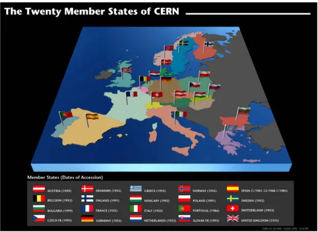
CERN, the European Organization for Nuclear Research, is an intergovernmental particle physics research organization with 20 Member States1. It was founded on 1955 by 12 countries, with Greece being one of them (Figure 1-1).
Figure 1-1: Map of Europe with the 20 member states of CERN
Its seat is in Geneva but its premises are located on both sides of the French-Swiss border (http://cern.ch/fp-procurement/map.html).
CERN’s mission is to enable international collaboration in the field of high-energy particle physics research and to this end it designs, builds and operates particle accelerators and the associated experimental areas. The necessary state-of-the-art technology is developed in several scientific fields such as particle accelerator and detector engineering, material science, electronics, informatics etc. At present, more than 10 000 scientific users from research institutes all over the world are using CERN’s installations for their experiments.
The accelerator complex at CERN is a succession of machines, built during its 50 years of successful operation, with increasingly higher energies. Each machine injects the beam into the next one, which takes over to bring the beam to an even higher energy, and so on. The flagship of this complex is the Large Hadron Collider (LHC) as presented in Figure 1-2:
1 The CERN Member States are currently Austria, Belgium, Bulgaria, the Czech Republic, Denmark,
Finland, France, Germany, Greece, Hungary, Israel*, Italy, the Netherlands, Norway, Poland, Portugal, Romania**, the Slovak Republic, Spain, Sweden, Switzerland and the United Kingdom.
* Associate Member State in the pre-stage to Membership ** Candidate for accession
Figure 1-2: The accelerator complex of CERN
1.2 THE RESEARCH PROGRAM OF CERN
After the acceleration of the particle beams to the desired energies, the beams are focused and made to collide with each other or with fixed targets. Detectors observe and record the results of these beam collisions at the Interaction Points (IP).
Such collisions are part of the experiments conducted at CERN, which collaborate and study phenomena of the modern particle physics. An indicative example of the collaboration of the experiments is the trajectory followed by the LHC particle beam, throughout the accelerator complex of CERN. The proton beam is generated out of hydrogen nucleus in the LINAC accelerator which passes it in the BOOSTER synchrotron. Afterwards, the particle beam is injected in the PS and then to SPS accelerators, sequentially. Finally, it is injected into LHC. In LHC, it will gain its maximum energy and collide in one of the IP of LHC where one of the detectors (ATLAS, CMS, ALICE or LHC-b) is situated. Each of the LHC detectors studies several areas of physics. On the other hand, and according to the overall schedule and experimental priority, the generated particle beam could be alternatively injected in one of the non-LHC experiments (AD, ISOLDE, etc.).
Figure 1-3: A Higgs Boson Event: A Higgs boson plus a jet in the opposite direction where the Higgs boson decays to two Z bosons and one Z boson decaying to e+e- and the other to μ+μ
-In parallel to the existing experiments, scientists at CERN are pursuing advanced accelerator research and development for a machine to exploit the LHC’s discoveries at the high-energy frontier. The international collaboration of the Compact LInear Collider (CLIC study) is working on a concept for a machine to collide electrons and positrons (anti-electrons) head on at energies up to several TeV. This energy range is similar to the LHC’s, but by using electrons and their antiparticles rather than protons, physicists will gain a different perspective on the underlying physics.
In order to reach multi-TeV energies, high gradients are paramount and the CLIC novel Two-Beam acceleration concept, as proposed in 1986, provides a unique opportunity to reach multi-TeV energies with an e+ e– machine. The studies of this concept continued through the 1990s but got an increased focus and importance by a CERN Council initiative in 2004 to increase the efforts towards producing a Conceptual Design Report (CDR) on the timescale of 2010 in order to match the expected start of and first physics results from the LHC.
The CLIC study is hosted by CERN and the CLIC test facilities at CERN have been and remain the central part of the project. However, many other test facilities around the world conduct experiments and study the key parameters for such a machine. Since 2008 the focus has been on addressing a set of key feasibility issues for a multi-TeV machine.
1.3 CLIC STUDY OVERVIEW AND KEY ISSUES
The CLIC study (Figure 1-4) is focused on the design of an e- e+ linear collider at colliding beam energy of 3 TeV with a luminosity of 2·1034 cm-2 s-1. In parallel, an equally interesting design is developed at a deduced lower energy, set to 500 GeV with the same luminosity. The required luminosity can be reached with powerful beams (14 MW each) colliding with extremely small dimensions and high beam stability. The accelerated particle beams have dimensions of 45 nm in the horizontal plane and 1 nm in the vertical plane at the IP. These small dimensions can only be obtained with extremely small emittance.
Figure 1-4: The CLIC layout at 3 TeV
The CLIC layout derives from specific features inherent to linear colliders that strongly influence the design:
• The two linacs accelerate the electron and positron beams in a single pass. As a consequence, high acceleration fields are required in order to keep the length of the collider to within reasonable limits.
• After acceleration, the two beams collide only once. In a circular machine the counter-rotating beams collide with a high repetition frequency (tenths of kHz range). The repetition frequency of a linear collider by contrast is typically 5 – 100 Hz.
Thus, the challenging design parameters2 of CLIC are necessary to be met, so as to provide the required luminosity for the particle physics experiments. The CLIC innovative scheme has a number of key issues. A key issue is defined for each case that the parameter specification happens to be above the present state-of-art. Several key issues have been identified for CLIC according to the study of the technical systems of the machine. The main categories for the CLIC key issues are feasibility, performance, cost and powering issues.
2
Design parameters such as: accelerating field, RF frequency of the main linac, RF power source,
Affordable cost and power consumption, in addition to the beam performance beyond both present energy and luminosity frontiers, impose the development of an innovative Two-Beam acceleration scheme.
1.4 THE CLIC TWO-BEAM ACCELERATION SCHEME
The key issues have also led to the choice of a room temperature based system on copper Accelerating Structures3 (AS). The field that accelerates the particle beam is generated by the AS which are fed with very high radiofrequency power.
In the CLIC Two-Beam acceleration scheme (Figure 1-5) the accelerating power is transported to the AS by a second electron beam, the Drive Beam (DB), which runs parallel to the Main Beam (MB). The DB is generated at the central campus of the CLIC complex. The beam power is extracted from the DB and converted to RF power in dedicated RF components called Power Extraction and Transfer Structures (PETS). Then it is transported to the AS of the MB covering a distance of about 60 cm. One PETS unit provides RF power for two AS (a number which depends on the high-power capability of the PETS). The stagger between the two linacs (MB and DB) is made to give the correct relative RF-to-beam timing. The novel scheme of Two-Beam acceleration has never been built and operated before.
Figure 1-5: The CLIC Two-Beam acceleration scheme
CLIC has a single tunnel, which houses the MB, the DB and the transfer lines. The CLIC Two-Beam acceleration scheme offers good power efficiency. The transport power to the place where it is converted to RF is done by an electron beam, which is nearly lossless. The beam would pass through several collider systems (delay loop,
combiner ring, damping ring, beam delivery system, etc.) before it reaches the IP.
1.5 THE CLIC TWO-BEAM MODULES 1.5.1 Description and types of Modules
The CLIC two-beam configuration is formed by “repeated Modules”. The Modules (or Two-Beam Modules) are the smallest repetitive units of the collider (Figure 1-6) assembled in series to form both the main and the drive linac. The Modules include all the main RF components and focusing magnets of the machine.
3 Normal conducting accelerating cavities
MB DB
Figure 1-6: Schematic layout of CLIC Type-0 Module
Five types of Modules are defined in order to accommodate all needed configurations and the challenging optics (focus) requirements for the particle beam (Figures 1-6 and 1-7). The MB of the Module 0 contains only AS whereas the Modules of Type-1 up to Type-4 include also MB-quadrupoles (MBQs) of variable length. The MBQs take the place of two (2), four (4), six (6) or eight (8) AS according to the type of the Module (Figure 1-7).
Figure 1-7: Schematic layout of CLIC Modules with MBQs
The RF components of the Module are mounted on dedicated alignment girders which are parts of the supporting system. The Module length is presently 2010 mm. Along with several other technical parameters, the mechanical and thermal stability of the overall system dictate it. Magnetic field simulations show that the DB-quadrupoles (DBQs) need to have a length of 270 mm and 1 m of spacing in between them. The
remaining space is occupied by the PETS and the Beam Position Monitors (BPMs). The length of 30 mm is reserved for the inter-girder connection. A small number of special Modules with only MBQs and DBQs are needed at each DB linac sector where each DB is fed in and out.
1.5.2 Technical systems
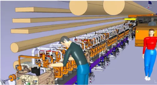
The Two-Beam Module design has to take into consideration the requirements for the different technical systems. The main components are designed and integrated to optimize the filling factor and gain in compactness. Figure 1-8, shows a 3D view of a typical Two-Beam Module, as a result of the integration of all needed components. In the following subsections all main technical systems are described in rough terms. Some repetition of the material shown also in the specific chapters of these systems is unavoidable and essential.
Figure 1-8: 3D view of the CLIC Two-Beam Module (Type 1)
RF System 1.5.2.1
The main components of the RF systems are the AS, the PETS, and the RF network comprising the inter-beam waveguides and the RF components. The main parameters of the RF structures are listed in Table 1-1.
Length (mm) Aperture (mm) Gradient (MV/m) Power (MW)
AS 230 5 100 64
PETS 308 23 6.5 136
Table 1-1: Main parameters for the RF structures
The design of the AS (for the MB) is based on Oxygen-Free Electronic copper disks which are bonded together to form a stack. The inside cell geometry is adapted to the manufacturing process, based on the bonding of disks with one side being flat and the other side carrying all the cell features. All cells of each AS are communicating with each other via their irises in their centre. These irises are used for the Two-Beam
MAIN BEAM DRIVE BEAM ALIGNMENT SYSTEM DB QUADRUPOLE VACUUM MANIFOLDS CRADLE STABILIZATION UNIT ACCELERATING
STRUCTURE COOLING CIRCUIT COMPACT LOAD VACUUMPUMP MB QUADRUPOLE
REFERENCE SPHERE
GIRDER
PETS PETS ON-OFF MECHANISM VACUUM
acceleration of the particle beam. Several features of the RF system (damping loads, Wakefield Monitors, compact couplers, waveguides, etc.) are brazed directly on the AS. The sophisticated function of the AS is based on their optimized design.
Part of the RF system (for the DB) with major significance is the PETS. A PETS is comprised of eight bars separated by damping slots. It is a passive microwave device in which the particle beam (in bunches) interacts and gains excitation. The RF power is produced in the PETS and then collected and delivered to the AS (of the MB) via the waveguides of the RF network. Several features such as the compact coupler, High Order Mode damping loads, “ON-OFF” mechanism, absorbers, etc. make part of the Power Extraction and Transfer System.
Cooling System 1.5.2.2
Most of the RF input power is dissipated as heat in the module structures. All Module types require a different cooling layout, because of the MBQ which comes in four different configurations. Apart from the thermal dissipation, requirements for the cooling system are governed by the requirements of vacuum, alignment, and mechanical stability. Furthermore, vibration should also be taken into account. Vibrations of the lattice elements, if not properly corrected, can result in a loss in performance by creating unacceptable emittance growth in the linear accelerator and relative beam–beam offsets at the interaction point.
The cooling system is using circulating water to cool down the components of the accelerator. It is worth mentioning that not only the nominal centre-of-mass energy of 3 TeV should be fulfilled by the cooling system but also some other intermediate settings such as 0.5 TeV. The power dissipation of a 21 km linac is about 70 MW and about 95% is cooled by water. The temperature difference (ΔΤ), which is considered during operation across the Two-Beam Module, is of a range of 20 K.
Vacuum System 1.5.2.3
The present baseline for the Two-Beam Module vacuum system excludes the possibility of heating the vacuum enclosure for geometrical stability reasons, leading thus to an unbaked system. Field ionization studies on the fast-ion beam instability result in a vacuum specification that is lower than the usual unbaked vacuum pressure (of the order of 10-7–10-8 mbar) by two orders of magnitude. To mitigate this problem, high speed pumping and a large vacuum conductance are needed.
The vacuum envelope is mainly the ensemble of RF system. In addition, vacuum chambers for the quadrupoles are also needed. For the Modules other than Type-0, drift tubes are required, only for the DB, based on the same design as of the DBQ beam pipe. Also a vacuum chamber is integrated in the MBQ during its assembly. The pumping system must not induce vibrations, especially to the MBQ stabilization system. A combination of NEG pumps with high pumping speed and a sputter ion pump is used.
Magnet System and magnet powering system 1.5.2.4
The magnet system is mainly composed of the DBQs and the MBQs. Among the major components of the Two-Beam Modules are the MBQs, needed for the focusing of the e+/e- MB along the linacs. The MBQs have different lengths as shown in Table 1-2.
Table 1-2: MBQs types (quantities for two linacs)
Since the MBQ has its unique and challenging stability requirements, it is essential that it is housed on its independent stabilization system. Thus, hexapod supports were dedicatedly designed to fulfil its explicit stability requirements. The total number of the MBQs is 2010 units per linac.
Each Two-Beam Module contains two DBQs. The decelerators therefore contain 41 400 quadrupoles in total. This will be the largest family of magnets in the CLIC complex. In the Module baseline proposal, the allocated space for the DBQ is constant all along the decelerators. The working gradient varies by one order of magnitude along the decelerator (from 81.2–8.12 T/m). This condition will satisfy the beam optics requirements along each decelerator sector, i.e., to provide an integrated gradient varying from 12.2 T down to 1.2 T as the average Drive Beam energy decreases from 2.5 GeV down to 0.25 GeV.
The radiation levels in the MB tunnel may reach 120 mSv/year, implying a substantial impact on the powering of the 50 000 magnets. If the power converters were to be placed in the tunnel, several aspects would be affected, namely the mean time between failures, efficiency, precision, control, and volume. Therefore, the powering of all magnets is done from dedicated radiation-free caverns, one per accelerating sector. Whereas the specification for the power converters is eased by the radiation-free environment, much more cabling will be required since the mean distance between a Module magnet and its power converter is about 260 m.
Supporting System 1.5.2.5
All the RF components (except from the MBQs) of the Two-Beam Modules are installed and aligned on an innovative supporting system. The Module supporting system is mechanically articulated throughout the entire length of the DB linac. The mechanical continuity of the MB supports is interrupted only by the individual supports of the MBQs. The supporting system is constituted out of several components (girders, V-shaped supports, cradles, U-clamps, etc.) to fulfil the various technical requirements for support and stabilization of the RF components. Their in-depth investigation, study and development shall be discussed in the forthcoming chapters.
Alignment System 1.5.2.6
The alignment of the Two-Beam Module is divided into two steps:
• Mechanical pre-alignment which takes place when the beam is off: The mechanical pre-alignment is also divided in two phases:
o It starts with the determination of the position of the components with the combination of two measurement networks: the Metrological Reference Network (MRN) and the Support Pre-alignment Network (SPN).
MBQ type Magnetic length (mm) Total Quantity for CLIC
Type-1 350 308
Type-2 850 1276
Type-3 1350 964
o And concludes with the re-adjustment of the supports with a sub-micrometric resolution over a range of ± 3 mm allowing displacements along 3 DoF (to achieve the necessary alignment of the particle beam passing through the RF components).
• Active (continuous) alignment: Once the machine is switched-on, the active alignment takes over the fulfilment of the requirements. In this step, the supports are re-adjusted based on the real-time position of the particle beam. The total error budget in the determination of the position of the components has been calculated to be 14 μm for the AS and 17 μm for the MBQs.
Stabilization System 1.5.2.7
The dedicated stabilization system reassures that the displacements imposed at the centre of the magnetic field stay below the acceptable limits of the safe magnet operation. The integrated root mean square (r.m.s) of the absolute vertical displacements of the magnetic field centre of each MBQ must stay below 1.5 nm for frequencies above 1 Hz. Similarly, it should stay below 5 nm in the horizontal direction. To reach such a level of mechanical stability for the MBQ, ground vibration measurements in operating particle accelerators have shown that a mechanical stabilization system is needed under each quadrupole.
The MBQ stabilization strategy is based on a stiff moving support equipped with piezoelectric actuators. The measurement of the relative displacement takes place between the quadrupole and an inertial reference mass (seismometer). The transmission of vibrations to the magnet support at low frequencies is then actively reduced. The vibration background is composed of a seismic background combined with technical noise. The main reason for the choice of this strategy is the robustness against external disturbances.
The displacement range and the stiffness of the actuators also allow one to reposition the magnet in vertical and lateral direction between the particle beam pulses with steps up to 50 nm in a range of ± 5μm.
Beam instrumentation 1.5.2.8
The Two-Beam Module instrumentation mainly consists of the Beam Position Monitors (BPMs) and Beam Loss Monitors (BLMs). These devices measure the position and quality of the particle beam and provide feedback.
The BPM for the MB consists of two cavities: a position cavity measuring both x and y directions and a reference cavity measuring the beam charge and phase. Both cavities are resonant at 14 GHz. The BPM for the MB is connected rigidly to the MBQ with no possibility to adjust its position. Alignment targets are mounted on the top in order to measure the relative BPM position with respect to the quadrupole. For the DB, there is one BPM in front of each DBQ. Their design is based on striplines. Such striplines are built into the vacuum chamber of each DBQ. Consequently, the BPMs of the DB are also rigidly connected on the magnets via a special support, of which one end is welded on the vacuum chamber (which goes through the DBQ). The other end is connected to the PETS. Target alignment spheres are mounted on the top side of the BPM, enabling to measure the mechanical centre with respect to the magnetic centre.
The beam instrumentation measuring the beam intensity, transverse and longitudinal profiles occur in relatively small quantities. They are allocated on special girders at the end of each decelerator section for the DB and on Module Types 1 to 4 for the MB.
Handling and transport 1.5.2.9
The space required for the Module transport and installation in the tunnel has a major influence on the tunnel cross-section. Studies were therefore carried out to identify how the Two-Beam Modules could be safely transported and installed in the tunnel. An equally important goal is feeding several design requirements, related to the transport and installation, into the overall Module design. Such requirements have also been included in the design of the supporting and positioning systems.
A large amount of Modules and their installation interfaces to the ground need to be transported and installed in the tunnel. The big numbers confirm the high importance for optimisation of the overall strategy of the Module transport so as to allow for a rapid and efficient operation. The Table 1-3 presents the number of Modules.
Item Quantity (at 3 TeV) Quantity (at 500 GeV) Dimensions (mm) Mass (kg) Per sector Total Per sector Total - - Modules 436 20924 436 4248 2010×1550×1200 1500 Ground installation interfaces 436 20924 436 4248 2010×1550×1200 200
Table 1-3: Transport study input: Number of Modules for tunnel installation
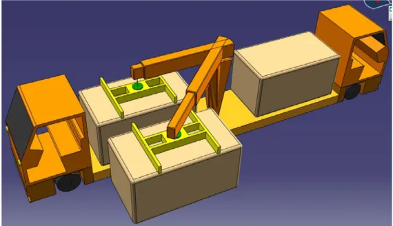
At the installation positions of the Modules in the tunnel, their interfaces to the ground arrive, are installed and aligned, at first. After that, each Module arrives with the special transport vehicle, as shown in Figure 1-9, and it is installed from above so as not to interfere with the ground interfaces and alignment equipment, which are already in place.
A conceptual design of the vehicle with its own on-board lifting equipment is produced in order to reserve the necessary space in the design integration of the tunnel. In addition, the installation methodology foresees the removal possibility of a previously installed Module, if major repairs are needed.
The design of the supporting system adapts to the Module design for transport, which requires the use of lifting points and support points to allow the whole sequence of transport and handling operations. These operations will be needed during the phases of Module assembly, testing, storage, road transport to access points, lowering into the cave, tunnel transport, and tunnel installation. The study includes all transport restraints and special lifting beams to be used when handling fully assembled Modules during the installation process.
Figure 1-9: Tunnel handling and installation representation for the CLIC Two-Beam Module
This kind of strict strategies for the transport and installation principles has majorly influenced several fabrication points of the supporting system. The technical details and the investigation of the parameters, which were taken into consideration, will be discussed in the dedicated chapter 4.
Chapter 2.
THE SUPPORTING SYSTEM OF
THE CLIC TWO-BEAM
2.1 DESCRIPTION OF THE CLIC SUPPORTING AND POSITIONING SYSTEM
The micro-precision CLIC RF structures will be aligned on a specially developed supporting system. The fundamental supporting components of such a system are the so-called girders. The girder design constraints are mainly dictated by the beam physics and RF requirements. All girders are mechanically interconnected constituting a continuous system called “Snake System” (Figure 2-1). This system allows for the precise alignment on the overall length of the two linacs. Through the “Snake System” the position of the girders is monitored and re-aligned.
Figure 2-1: Supporting system concept: "Snake System"
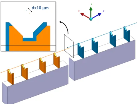
The RF structures are stabilized and supported on the girders via the so-called V-shaped supports (Figure 2-2). The design of this intermediate component has raised several issues regarding its mechanical behaviour and integration in the Module envelope (space availability, etc.).
Besides their mechanical behaviour, the V-shaped supports demand a firm fixation on the girders. Again, the study and design of such interconnectivity and assembly techniques were challenging. Particularly, along with the design of the V-shaped supports several different technical patterns were studied on a case-by-case basis to achieve the coupling of the V-shaped supports and girders
Figure 2-2: CLIC Two-Beam Module (Type-0) supporting system
42.1 km
MB
ARTICULATION POINTS OF THE SNAKE SYSTEM
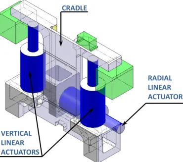
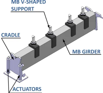
CROSS SECTION VIEW DB RF-COMPONENTS RF-COMPONENTS SUPPOR. SYSTEM SUPPOR. SYSTEM MB V-SHAPED SUPPORT ACTUATORS MB GIRDER DB GIRDER DB V-SHAPED SUPPORT CRADLE