RESEARCH OUTPUTS / RÉSULTATS DE RECHERCHE
Author(s) - Auteur(s) :
Publication date - Date de publication :
Permanent link - Permalien :
Rights / License - Licence de droit d’auteur :
Institutional Repository - Research Portal
Dépôt Institutionnel - Portail de la Recherche
researchportal.unamur.be
University of Namur
A Deep Blue B,N-Doped Heptacene Emitter That Shows Both Thermally Activated
Delayed Fluorescence and Delayed Fluorescence by Triplet-Triplet Annihilation
Suresh, Subeesh Madayanad; Duda, Eimantas; Hall, David; Yao, Zhen; Bagnich, Sergey;
Slawin, Alexandra M.Z.; Bässler, Heinz; Beljonne, David; Buck, Manfred; Olivier, Yoann;
Köhler, Anna; Zysman-Colman, Eli
Published in:
Journal of the American Chemical Society
DOI:
10.1021/jacs.9b13704
Publication date:
2020
Document Version
Peer reviewed version
Link to publication
Citation for pulished version (HARVARD):
Suresh, SM, Duda, E, Hall, D, Yao, Z, Bagnich, S, Slawin, AMZ, Bässler, H, Beljonne, D, Buck, M, Olivier, Y, Köhler, A & Zysman-Colman, E 2020, 'A Deep Blue B,N-Doped Heptacene Emitter That Shows Both Thermally Activated Delayed Fluorescence and Delayed Fluorescence by Triplet-Triplet Annihilation', Journal of the
American Chemical Society, vol. 142, no. 14, pp. 6588-6599. https://doi.org/10.1021/jacs.9b13704
General rights
Copyright and moral rights for the publications made accessible in the public portal are retained by the authors and/or other copyright owners and it is a condition of accessing publications that users recognise and abide by the legal requirements associated with these rights. • Users may download and print one copy of any publication from the public portal for the purpose of private study or research. • You may not further distribute the material or use it for any profit-making activity or commercial gain
• You may freely distribute the URL identifying the publication in the public portal ?
Take down policy
If you believe that this document breaches copyright please contact us providing details, and we will remove access to the work immediately and investigate your claim.
A Deep Blue B,N-Doped Heptacene Emitter That Shows Both
Ther-mally Activated Delayed Fluorescence and Delayed Fluorescence by
Triplet Triplet Annihilation
Subeesh Madayanad Suresh,a Eimantas Duda,b David Hall,a,c
Zhen Yao,a Sergey Bagnich,b Alexandra M. Z. Slawin,a Heinz Bässler,b David Beljonne,c Manfred Buck,a* Yoann Olivier,c,d* Anna Köhler,b* and Eli
Zysman-Colmana*
a
Organic Semiconductor Centre, EaStCHEM School of Chemistry, University of St Andrews, St An-drews, UK, KY16 9ST. E-mail: [email protected]
bSoft Matter Optoelectronics, BIMF & BPI, University of Bayreuth, Universitätsstraße 30, 95447
Bay-reuth, Germany. E-mail: [email protected]
cLaboratory for Chemistry of Novel Materials, University of Mons, 7000, Mons, Belgium. d
Unité de Chimie Physique Théorique et Structurale & Laboratoire de Physique du Solide, Namur Insti-tute of Structured Matter, Université de Namur, Rue de Bruxelles, 61, 5000 Namur, Belgium.
Abstract
An easy-to-access, near UV-emitting linearly extended B,N-doped heptacene with high thermal stability is designed and synthesized in good yields. This compound emits thermally activated delayed fluorescence (TADF) at ambient temperature from a multi-resonant (MR) state and represents a rare example of a non-triangulene-based MR-TADF emitter. At lower temperatures triplet-triplet annihilation dominates. The compound simultaneously possesses narrow, deep-blue emission with CIE coordinates of (0.17, 0.01). While delayed fluorescence results mainly from triplet-triplet annihilation at lower temperatures in THF solution, where aggregates form upon cooling, the TADF mechanism takes over around room temperatures in solution when the aggregates dissolve, or when the compound is well dispersed in a solid matrix. The potential of our molecular design to trigger TADF in larger acenes is demonstrated through the accurate prediction of ∆EST using correlated wavefunction-based calculations. Based on these calculations, we
pre-dicted dramatically different optoelectronic behavior in terms of both ∆EST and the optical energy gap of
two constitutional isomers where only the boron and nitrogen positions change. A comprehensive struc-tural, optoelectronic and theoretical investigation is presented. Further, the ability of the achiral molecule to assemble on a Au(111) surface to a highly ordered layer composed of enantiomorphic domains of race-mic entities is demonstrated by scanning tunneling race-microscopy.
Introduction
The high charge carrier mobility of graphene1, 2 is an extremely appealing property that can be
exploited in electrode design3 for optoelectronic devices. To extend the applicability of graphene and its
derivatives, the structure of the materials must be modified to modulate their band gaps. Reducing the dimensionality of graphene in the form of graphene quantum dots and graphene nanoribbons is one way to induce a defined band gap that overlaps with the visible spectrum in these materials.4 Another strategy to
modulate the optoelectronic properties of nanographenes, which are graphenoid fragments, involves het-eroatom doping. In particular, boron-, nitrogen-, sulfur-, and phosphorus-doped organic nanographene ma-terials have been identified as possessing useful properties in energy-related research such as supercapaci-tors,5-8 lithium ion batteries,9-12 fuel cells,13-16 solar cells,17-19 and sensors.20-23 Recent advances in synthetic
methodology in the form of surface-assisted coupling24-27 or amplified growth28-30 has permitted access to
heteroatom-doped nanographene materials. The smallest heteroatom-doped nanographene compounds are frequently readily synthesized in good yields using intramolecular Friedel-Craft-type reaction. However, this synthetic approach demands the availability of electron-rich precursor molecules containing functional groups such as hydroxyl,31, 32 amino,33-37 imino,38, 39 halogeno,40-42 or trimethylsil groups,43, 44 which
neces-sitates often a multi-step synthesis of these precursors.
In 2015, Hatakeyama et al.45 introduced a one-step borylation method to generate polycyclic
aro-matic hydrocarbons (PAHs) with a 1,4-oxoborine substructure through ortho-lithiation of 1,4-diaryloxyben-zenes and subsequent transmetalation to boron, followed by electrophilic borylation of the arene. Later, the same group demonstrated the versatility and the impact of the one-step borylation through the synthesis of boron- and nitrogen-containing PAHs, which they showed to be high-performance blue-emitting thermally activated delayed fluorescence (TADF) materials for organic light-emitting diodes (OLEDs). The synthetic protocols were further simplified and a series of B-N-doped nanographenes could be obtained in a two-step synthesis consisting of a key multi-borylation of a triarylamine intermediate. By adjusting the boron source,
Brønsted base and reaction temperature, selectively doublely and triply borylated products could be ob-tained.45-50
Among the striking advantages of these molecules is their narrow emission spectra (FWHM = 14-40 nm) compared to the conventional donor-acceptor TADF molecules (FWHM = 70-100 nm) because of their low reorganization energy. The origin of the TADF in these compounds originates from the combina-tion of short-range charge-transfer and delocalized hole and electron wavefunccombina-tions that effectively reduces the exchange and the singlet-triplet energy gap while maintaining a large radiative decay rate.51 Since 2016,
a number of improved-performance B,N-doped analogs all showing resontant TADF (R-TADF) have been developed as emitters for OLEDs.
Incorporating main group elements into the framework of larger acenes was previously known as a very effective strategy to tune the property of the parent π conjugated systems,52 which are otherwise
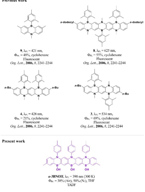
inaccessible in non-heteroatom-doped acenes. In particular, the integration of tricoordinate boron atoms within to the PAH can result in the emergence of new optoelectronic properties. In 2006, Takayuki et al., reported a series of ladder-type fused azaborines by extending number of boron and nitrogen atoms in the aromatic acenes.53 In each of the examples shown in Figure 1 the boron and nitrogen atoms are disposed
para with respect to each other, a regiochemistry that is necessary but not sufficient to turn on TADF in multiresonance emitter. As the conjugation length of the B,N-doped acenes is extended in the series where the relative positions of the boron and nitrogen atoms alternates, there is a pronounced observed red-shift of the photoluminescence (PL) spectrum from 9 to 3 to 8. Surprisingly, when there is a regioregular exten-sion of the B,N-doping, as in 4, extended conjugation across the acene is suppressed, which leads to a very small red-shift of the PL spectrum upon extension of the acene (compare 3 versus 4); these compounds were identified as fluorescent materials, and a detailed photophysical study of these B.N-doped acenes was
not provided.
Figure 1. Chemical structures of previously reported B,N-doped acenes and the structure of our molecule.
In the context of our previous theoretical study that predicted that higher-order B,N-doped acenes should show promisingly small EST and high oscillator strength, and mindful of the limited prior art
sum-marized above, we targeted a linearly extended B-N-doped heptacene. Compound α-3BNOH was obtained from a three-fold electrophilic borylation49 of triamine 2 in good yield (Scheme 1), which itself was
syn-thesized efficiently in two steps by a sequence of Ullman54 and Buchwald-Hartwig55 cross-coupling
reac-tions. The OH functionalities are introduced during the isolation of α-3BNOH due to hydrolysis of the B-Br bonds. Extracting the crude reaction mixture in EtOAc followed by aqueous wash afforded crude
α-3BNOH, which was then redissolved in MeCN and placed in an ultrasonic bath for 15 min. The formed
off-white precipitate was then filtered and washed with acetonitrile, DCM and hexane and dried to afford pure α-3BNOH. The identity and purity of α-3BNOH was established from a combination of 1H, 13C NMR
spectroscopy, high-resolution mass spectrometry, elemental analysis and single crystal X-ray diffraction analysis. High themal stability was noted for α-3BNOH on thermogravimetric analysis (TGA). Decompo-sition temperature (Td), defined as the 5% weight loss of the material was calculated to be 554 °C (Figure
S10).
Scheme 1. Synthesis of α-3BNOH. a) p-toluidine, Cu, CuI, K2CO3, reflux 5 days b) di-p-tolylamine,
Pd(OAc)2, [(t-Bu)3PH]BF4, NaOt-Bu, toluene, 110 °C, 24 h c) BBr3, 1,2-4-trichlorobenzene, 200 °C, 12 h.
Single crystal analysis were carried out to identify the structural orientation of α-3BNOH (Figure
2) in the solid state. The three tolyl rings attached to the nitrogen are aligned nearly orthogonally (torsion
the unit cell. The hydroxyl groups on the boron participate in hydrogen bonding with the THF solvent molecules in the crystal. There are no other intermolecular short contacts of note. In line with previous reports,45, 49 B-C (1.543-1.555 Å) bond lengths are longer than both C-C (1.388 – 1.421 Å) or C-N
(1.392-1.444 Å) bonds present in the molecule. The heptacene core is nearly planar but bends because of the asymmetry in C-B-C and C-N-C bond angles due to the -stacking interactions between the pendant phenyl rings.
Figure 2. ORTEP diagram of a) α-3BNOH obtained by single crystal X-ray analysis b) and c) side views. Thermal ellipsoids are displayed in 50% probability level.
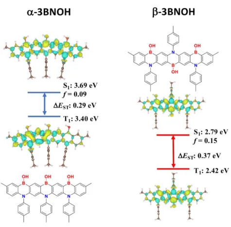
We then applied spin-component scaling second order approximate coupled-cluster (SCS-CC2) to model α-3BNOH as well as its alternative B,N-doped heptacene analog, β-3BNOH (Figure 3). The differ-ence density plots of both the S1 and T1 states are reminiscent of other R-TADF emitters where there is an
alternating pattern of increasing (in yellow) and decreasing (in green) density on adjacent atoms. A smaller ∆EST of 0.29 eV was calculated for α-3BNOH compared to that of β-3BNOH (EST = 0.37 eV). Though
somewhat higher than ideal for TADF emitters, we nevertheless expected that reverse intersystem crossing (RISC) would be thermally activated in -3BNOH with potentially the assistance of higher-lying excited
triplet states to the upconversion process (see Figure S12 for an energy diagral including higher-lying sin-glet and triplet excited states). A slightly larger oscillator strength, f, is predicted for β-3BNOH (0.15) compared to α-3BNOH (0.09). Most striking is the large change in the predicted energies of the excited states, with vertical excitation from S0 to S1 at 3.69 and 2.79 eV for α-3BNOH and β-3BNOH, respectively,
corresponding to a difference of 0.9 eV. This prediction is consistent with the observed red-shifting of the emission in the previously reported B/N-doped heptacenes (vide supra). The HOMO and LUMO electronic distribution is provided in the ESI (Figure S11).
Figure 3. Different density plots for lowest singlet and triplet excited states for 3BNOH (linear, -, and alternating, -isomers) calculated in the gas phase using SCS-CC2. Blue colour represents an area of de-creased electron density and yellow represents an inde-creased electron density between the ground and excited states.
The electrochemical behavior of α-3BNOH was measured by cyclic voltammetry (CV) and differ-ential pulse voltammetry (DPV) in deaerated THF with 0.1 M tetra-n-butylammonium hexafluorophosphate as the supporting electrolyte (Figure 4a). The oxidation potential, Eox, determined from the peak value of
first oxidation wave of DPV curve is 1.17 V versus SCEcorresponding to a HOMO energy level of -5.97 eV (EHOMO = −(Eoxonset + 4.8) eV.56, 57 The oxidation is irreversible, and no reduction wave was found within
the electrochemical window of the solvent. Therefore, the LUMO energy level of -2.81 eV was inferred by subtracting the optical energy gap, Eg, estimated from the onset of the absorption spectrum (Eg= 3.16 eV).
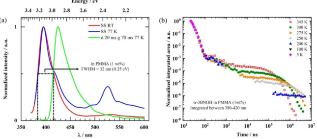
Figure 4. Solution-state optoelectronic measurements of α-3BNOH. a) Cyclic and differential pulse volt-ammograms measured in degassed THF with 0.1 M [nBu4N]PF6 as the supporting electrolyte and Fc/Fc+
as the internal reference (0.28 V vs. SCE).56 Scan rate = 100 mV s-1 b) Absorption, steady-state at 300 K
and emission at 77 K (steady-state and with 70 ms delay) measured in THF and steady-state emission at 300 K measured in PMMA (1 wt% emitter) spin cast film. exc = 325 nm. Inset figure shows PL of
α-3BNOH in THF at 300 K.
Figure 4b shows the photophysical properties of α-3BNOH in dilute THF solutions (10-5 M). The
UV-vis absorption spectrum shows a strong absorption band at 3.84 eV (323 nm), assigned to a π-π* tran-sition. The lowest-energy absorption band is found to be at 3.27 eV (379 nm) and is seen to arise from the combined contributions of the quasi-degenerate S1 and S2 excited states. Overall, this band appears to be
com-pounds 3, 4, 8 and 9 (Figure 1) where the most intense band was the lowest energy band. Qualitative agree-ment in the respective intensities of the absoption bands is achieved between experiagree-ment and theory, with SCS-CC2 calculations yielding oscillator strengths of 0.09 [0.11] for excitation into S1 [S3]. The larger
oscillator strength calculated for S3 than for S1 is explained by the larger spread of the excited state density
(see Figures S12 for S1 – S3) which involves a larger transition dipole moment in S3 than in S1. Similar to
the emission profile reported for compound 8 (Figure 1), α-3BNOH shows structured emission. Both com-pounds are ladder-type heptacene-based molecules containing para-disposed boron and nitrogen atoms. Aside from the pattern of the boron and nitrogen atoms, structural differences include the substituents found at both nitrogen and boron; for compound 8, mesityl groups are attached to boron and methyl groups are attached to nitrogen, while on α-3BNOH hydroxyl are substituted on boron and tolyl rings are connected to nitrogen. The photoluminescence spectrum at RT shows a structured profile with a sharp, near UV emis-sion band peaking at 3.18 eV (390 nm) and a shoulder at 3.03 eV (409 nm). Noteworthy is the very small full width at half maximum (FWHM) of 0.24 eV (31 nm), which we attribute to the rigid nature of the compound that does not allow for torsional motions.58-62 Due to the small Stokes’ shift of this emission and
its short lifetime (see Figures 4b), we can assign this blue emission peaking at 3.18 eV (390 nm) at RT to fluorescence. By contrast, heptacene and its substituted derivatives absorb and emit in the red. 63-66 The
second emission band, peaking at 2.81 eV (442 nm ) with a shoulder at (465 nm) for 77 K, has a long lifetime of 310 ms (Figure 4b), as evident from its monoexponential decay curve (Supporting Information). Due to its well-resolved vibrational structure, the large shift from the fluorescence and the long lifetime, it can be assigned to a triplet state. When measuring under steady-state conditions at 77 K, we observe both the fluorescence and the phosphorescence components. The ∆EST, determined from the 0-0 peaks of the
two bands at 77 K, is measured to be 0.31 eV, consistent with our SCS-CC2 calculations. The absolute photoluminescence quantum yield, PL, in 7.6×10⁻⁵ M THF at RT is 50%, which reduces to 38% upon
In order to obtain a deeper insight, we performed further photoluminescence measurements as a function of temperature, concentration, delay time after pulsed excitation and gate width. Figure 5 shows the relevant spectra. For a 7.6×10⁻⁵ M solution at room temperature (Figure 5a), we observe essentially the
fluorescence spectrum for all delay times for short gate times of 10 ns, albeit there is some small hypso-chromic shifting of the emission with increasing delay times. We point out that the resolution of the detector used for the time-resolved measurements of Figure 5 is lower than that of the spectrometer used for Figure
4, in particular in the blue spectral range. After a longer delay time of 1 s and gate width of 1 s, we still
observe the same deep blue emission, which clearly indicates an origin that involves intermediate long-lived triplet states.
In order to observe phosphorescence, it is necessary to cool the solution, e.g. by forming a glass at 5 K (Figure 5b). Using a long delay time of 30 ms and gate width of 15 ms, the structure phosphorescence spectrum is clearly visible. The fluorescence band shows the same small hypsochromic shift with increasing delay times as already observed at room temperature. In addition, a broad, unstructured band emerges in the green-to-red spectral range at short times that has fully disappeared by the s timescale. The broadness and lack of feature, along with the red-shift compared to the fluorescence band near 400 nm and the inter-mediate lifetime of less than 1 s is suggestive of an origin from a physical dimer or aggregate that may have formed when cooling; the driving force for aggregate formation at high dilution may be due in part to intermolecular hydrogen bonding as was observed by STM on gold surfaces, vide infra. To address this, we measured the PL in a freshly prepared, more dilute solution of 7.6×10⁻⁶ M, using a delay of 100 ns and
a 400 ns gate width (Figure 5c). Around 500 nm, there is only a weak signal that can hardly be distinguished from the fluorescence tail (red curve). When repeating the measurement after one day (blue curve) and after 2 days (green curve), a band centred at 500 nm emerges. After sonication of the solution for a few minutes, this signal dissappeared (black curve). Based on this observation, we associate the broad emission centred at 500 nm to interactions between adjacent chromophores, such as those prevailing in excimers, physical
dimers or aggregates.62 As molecular motion or reorientation is severely restricted at 5K, the most likely
origin of the emission are rather weakly bound H-type aggregates. Figure 5d displays the PL spectra taken during several time intervals that evidence that the broad emission at 500 nm decays within 1 s. It is remarkable that, for these concentrations, no such broad emission at 500 nm can be observed beyond 1 s (also in the glass of Figure 5b), even though phosphorescence prevails on a ms timescale. The lack of this broad emission and the rise of phosphorescence on a ms timescale implies that aggregated molecules do not act as trap sites for triplet states. We could observe long-lived emission from aggregates, i.e. aggregate phosphorescence, only when using more concentrated solutions or in thin films. This is detailed in the SI (Figure S14a, b). In passing, we mention that the singlet-triplet splitting in the aggregate is very small, on the order of about 70 meV.
Figure 5. Emission spectra of α-3BNOH in THF at 7.6 × 10⁻⁵ M as indicated a) at 300 K and b) at 5 K for
different delay times d and gate width g (smoothed data). c) At different times after preparation and after sonication (son), taken a with a delay of 100 ns and a gate of 400 ns. d) At 300 K for different delay times, d, and gate width, g, taken in a solution 2 days after preparation. The solid lines are smoothed curves through the lighter shaded data. For all data, λexc = 355 nm.
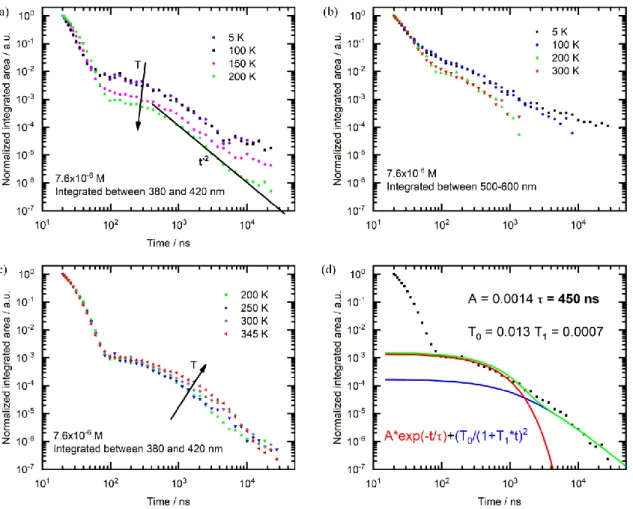
Figure 6 addresses the luminescence transients. In the blue spectral window from 380 – 420 nm, the PL taken from a dilute 7.6×10⁻⁵ M solution shows a decay from prompt fluorescence followed by a
delayed fluorescence component from about 50 ns onwards (see Figure 6a). This DF decay has a very similar intensity at 5 K and 100 K, yet it reduces relative to the prompt fluorescence upon heating to 150 K and 200 K (see Figure 6b). We note that the glass transition temperature Tg of THF is about 120 K. The
transient in the green-red spectral windows, 500 – 600 nm, show a similar evolution insofar that the 5 K and 100 K decays coincide, yet the relative intensity reduces upon heating to 200 K and 300 K. The signal between 500 nm and 600 nm is due to aggregates, and we attribute the reduction of this signal upon heating to the dissociation of the aggregates with temperature. Recalling that for THF, Tg is about 120 K, it is clear
that this process only sets in from about 150 K onwards. From the observation that the signal between 380 and 420 nm reduces in parallel to the signal between 500 to 600 nm upon heating we conclude that the existence of aggregates is a prerequisite for the delayed blue emission up to and including 300 K.
The most likely origin is that the blue delayed fluorescence results from triplet-triplet annihilation (TTA) that can occur in the aggregated material, which forms despite the high dilution. We recall that at these concentrations the emissive aggregates do not provide a significant number of traps for the (monomer) triplet states. We have measured the dependence of the steady-state emission, i.e. the blue signal, on the excitation power and found this to be linear (Figure S15). While a linear power dependence is often con-sidered to indicate a TADF process, we point out that this is evidently not the case here, as (i) the delayed fluorescence reduces upon heating up to 250 K instead of being thermally activated, and (ii) its intensity
evolution correlates with the aggregate concentration, while TADF should be independent of any aggrega-tion effects. In fact, a linear power dependence is characteristic for TTA if the TTA-process dominates over other radiative or non-radiative triplet decay channels.62 For pulsed excitation with triplet lifetimes of 30
ms or longer, this condition is easily fullfilled. This is confirmed by the time dependence of the DF signal. The 200 K signals shows the plateau followed by the t-2 decay that is characteristic for the DF decay, which
evolves as ([𝑇0] (1 + [𝑇⁄ 0]𝛾𝑡))2, where [𝑇0] is the initial triplet concentration and 𝛾 is the annihilation
constant. At lower temperatures, transport becomes increasingly dispersive thus reducing the slope towards t-1.
Having established that TTA prevails from 5 K to close to 300 K, we now consider the temperature regime from 300 K onwards (Figure 6c). It is evident how, upon heating, a thermally activated component emerges. Thus, it seems that there is a TADF component that becomes active above 300 K. The cross-over between the regimes where TTA and where TADF prevail is around room temperature. For the analysis of the TADF kinetics it is important to establish whether any contribution dominates at 300 K. We have there-fore measured the dependence of the decay transient on excitation power. A higher TTA rate due to a higher triplet concentration would alter the time where the plateau merges into the t-2 decay. We observe no change
in the decay transients upon increasing the fluence from 0.3 J to 30 J for a spot size of 4 mm diameter, even when using a more concentrated solution where aggregation should be stronger (See ESI, Figure S16). This suggests that at 300 K and above, the decay kinetics in the “shorter” time range up to a few s is controlled mostly by a monomolecular process such as TADF. At longer times above a few s, where the decay merges into a t-2 dependence, TTA evidently still prevails. Figure 6d shows a fit to the PL decay
considering a mono-exponential decay with a fixed lifetime of 450 ns to account for TADF and a decay according to [T0/(1+T1*t)]2 to account for TTA. A fit to the prompt fluorescence yields a lifetime of about
Figure 6. Photoluminescence transients taken in 7.6×10⁻⁶ M solution, excited at 355 nm, a) integrated
be-tween 380 nm and 420 nm and taken upon heating from 5 K to 200 K, with the green line indicating a slope of -2, b) integrated between 500 nm and 600 nm and taken upon heating from 5 K to 200 K, c) integrated between 380 nm and 420 nm and taken upon heating from 200 K to 345 K, d) integrated between 380 nm and 420 nm at 300 K. The red curve represents a monoexponential, A*exp(-t/τ), while the blue curve rep-resents a [T0/(1+T1*t)]2 fit, which is characteristic for the decay of a DF caused by TTA. The green line is
the sum of red and blue lines. The fitting parameters are shown in the figure.
It is not possible to derive a rate for the reverse intersystem crossing, 𝑘𝑅𝐼𝑆𝐶, from the dynamics
described above. Simply inserting the lifetime into the frequently used equations from the Monkman group, as is sometimes done, would give a nominal value of about 2×10⁶ s-1, which would be a high value for a
∆EST of 0.31 eV.67, 68 However, as has also been stressed by the Monkman group, in deriving these equations
a number of approximations are made that only hold when the quantum yield for DF, ΦDF, is about four
0.01ΦPF, consistent with the ∆EST value and previous MR-TADF emitters.48, 69 We note that the TADF
component seems to have an activation energy of only about 70 meV while the singlet-triplet splitting is in the range of 300 meV. This discrepancy has previously been accounted for by mixing with higher-lying excited states.68 SCS-CC2 calculations predict the presence of two higher-lying triplet states of energies
intermediate between T1 and S1, each of which has MR-TADF character (Figure S12). Here, the low value
may also relate to the fact that the TADF component superimposes on the TTA component. The reduction of the TTA contribution with increasing temperature due to the dissolution of any aggregates also reduces the observed increase in TADF, and the two processes are difficult to disentangle.
For electroluminescent device applications, it is essential to know how these properties translate into films. Figure 7 shows the spectra and transients obtained for α-3BNOH dispersed (doped) at 1 wt% into poly(methylmetacrylate) (PMMA).
Figure 7. α-3BNOH dispersed at 1 wt% into PMMA. a) Spectra taken under steady-state conditions at room temperature (red line, SS RT) and at 77 K (blue line, SS 77 K), and taken with a delay of 20 ms and a gate width of 70 ms at 77 K (green line). b) The decay of the luminescence signal, spectrally integrated from 380 – 420 nm, taken at different temperatures as indicated.
Comparison with the solution spectra shown in Figures 4 and 5 shows that the long-lived compo-nent peaking at about 425 nm (2.92 eV) at 77 K is the phosphorescence signal, and the short-lived band peaking around 395 nm (3.14 eV) is the fluorescence. In the PMMA matrix, the ratio between the integrated delayed fluorescence signal and the integrated prompt fluorescence increases significantly, so that ΦDF≈
0.20ΦPF. The FWHM is 0.25 eV (32 nm), i.e. nearly unaltered compared to the value in solution. The
singlet-triplet gap, EST, in the 1 wt% emitter doped in PMMA film is 0.22 eV, which is about 100 meV
smaller compared to that in THF solution. Such shifts are common for charge-transfer type states and result from different polarities of the solvent and matrix. The short-lived feature at 525 nm observed at 77 K is some emission from remnant excimers or aggregates that disappears below a s time scale (see Figure S17). It is gratifying that this does not prevail at room temperature, thus preserving the deep blue emission colour with CIE coordinates of x=0.17 and y=0.01 when dispersed at 1 wt% in PMMA. This represents a blue shift compared to DABNA-1, which has CIE coordinates of (0.13, 0.09) in an electroluminescent device, at the expense of a slightly larger FWHM (32 nm for α-3BNOH compared to 28 nm for DABNA-1 in an OLED).
The PL transients of the doped film show three distinct regimes. First, we observe a prompt decay component with a lifetime of 8.5 ns, identical to that in solution. Second, from about 100 ns to several s we observe a decay of unclear origin. Finally, towards longer times there is an exponential decay that is temperature activated. At room temperature, the lifetime of this mono-exponential decay is about 260 s (see Figure S18a). Evaluating the thermal activation of the long-lived decay gives an activation energy of 220 meV, which matches with the observed EST. (see Figure S18c) It does not show any dependence on
incident light intensity (see Figure S18b), identifying it as a monomolecular process. This, in combination with the thermal activation with an energy that matches the singlet-triplet splitting strongly suggests the 260 s lifetime to be a TADF signal. If fitted with a single exponential decay, then the signal in the inter-mediate range from about 100 ns to several s has a lifetime on the order of 0.5 s, though an interpretation
as a dispersive decay following a 𝑡−1 law would also be possible. It shows a small dependence on intensity
(see Figure S18b). Evidently, more detailed follow-up studies beyond the scope of this investigation are required to unambiously assign this intermediate feature. The photophysical data in solution and film is summarized in Table 1. Solvatochromic measurements have also been carried out in solution (Figure S19) yet they show no systematic shift with solvent polarity in agreement with the short-range charge transfer observed in the S1 excited state (see Figure 3).
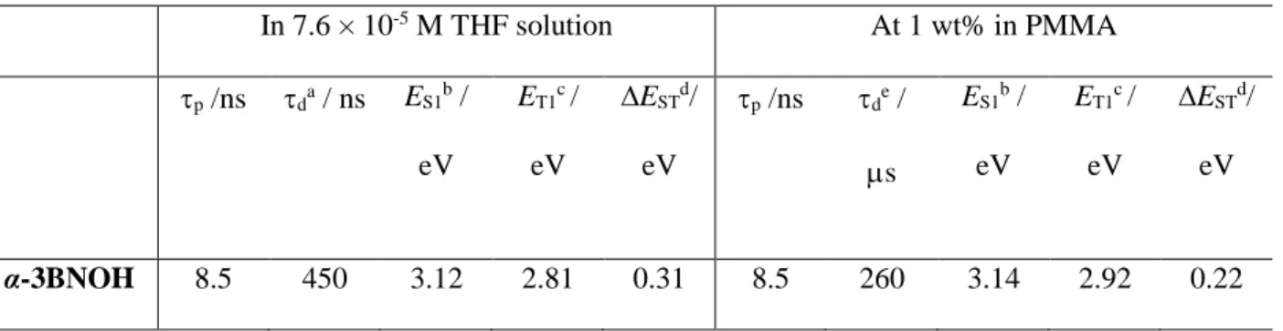
Table 1. Lifetime data and excited state energies for α-3BNOH in THF solution and in film.
In 7.6 × 10⁻⁵ M THF solution At 1 wt% in PMMA p /ns da / ns ES1b / eV ET1c/ eV ∆ESTd/ eV p /ns de / s ES1b / eV ET1c/ eV ∆ESTd/ eV α-3BNOH 8.5 450 3.12 2.81 0.31 8.5 260 3.14 2.92 0.22 a
exc = 355 nm at 300 K under vacuum, prompt component
p and delayed component
d obtained using a single exponentialdecays for each. b Obtained from the maxima of the PL steady-state spectrum at 77 K,
exc = 335 nm. c Obtained from the maxima of the PL spectrum at 77 K, exc = 355 nm. d EST = E(S1) – E(T1). e obtained using a single exponential
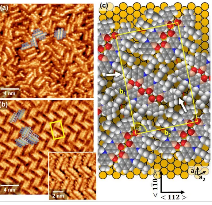
We next carried out scanning tunneling microscopy (STM) measurements to study the self-assem-bly process of α-3BNOH on a Au(111) surface. The focus was on the first layer which, through templating and modification of chemical interactions, is critical for the growth of thin films.70-72 Samples prepared at
two different temperatures (RT and 343 K) and a range of concentrations were investigated. The STM images at submolecular resolution of layers prepared from solutions of α-3BNOH (Figure 8) reveal a pro-nounced influence of concentration on the order of the layers as illustrated in Figure 8 whereas no noticeable influence of the preparation temperature was observed. Higher concentrations yield disordered layers as
evidenced by Figure 8a. In contrast, a highly crystalline herringbone structure is formed at the lower con-centration (Figure 8b) and in the intermediate concon-centration range above 200 M the two morphologies can coexist. In the STM images of both the disordered and crystalline layers of the individual molecules are clearly discernible with some of them overlaid by a footprint of the molecules outlining the acene back-bone and the three tolyl units. It is noted that the submolecular resolution is dependent on tip conditions as well as tunneling parameters. In the disordered layer the four benzene rings of the heptacene backbone are clearly resolved. A somewhat different tunneling contrast is seen in the large image of the crystalline layer where, even though less pronounced, the backbone is still resolved but also individal tolyl moieties show up as protrusions. The latter become even more clear using another set of tunneling parameters (inset of Figure 8b).
The basic units of the ordered layer consist of dimers with two achiral α-3BNOH molecules ar-ranged in a staggered fashion to yield two chiral enantiomeric entities. As seen from the molecular model displayed in Figure 8c, such a dimerization is favoured by the contour of the molecules and their supramo-lecular interactions comprising OH···H and C-H···O bonding. The herringbone structure is the result of an alternating arrangement of the enantiomeric dimers. While a herringbone packing has been observed for other acene monolayers like rubrene73 or pentacene,74 the present case is different as, instead of an achiral
monomer, chiral dimers are the units underlying the structure. The formation of dimers is impeded at the higher concentration due to kinetic barriers arising from interlocking of the molecules before they can ar-range into an ordered structure. This evidences that pairing of the molecules is a process occuring at the surface and not in the bulk solution.
Looking at the structural model of Figure 8c, the major intermolecular interactions in the monolay-ers are those resulting in dimer formation. Interactions between different dimmonolay-ers seem to be comparably
weak, even though not negligible as the alignment of the tolyl groups of adjacent molecules suggest as illustrated in the top left corner of Figure 8b. Also sterical hindrance is likely to play a role (sites marked by arrows), which would require some conformational adjustment. Therefore, the interaction between the acene backbone and the metal surface is considered the major driving force to minimize the energy of the system by maximizing coverage. Other dimer arrangements such as a linear structure mediated by interac-tions of tolyl moieties would result in a more open structure and, therefore, a lower coverage. The registry between substrate and lattice of the α-3BNOH layer also plays a role as domains are aligned along well defined directions of the substrate. Based on the STM data the unit cell marked by the yellow rectangles is proposed. Containing 4 molecules (211 Å2 per molecule) it is an essentially rectangular unit cell with
pa-rameters of 𝑏1= √163 𝑎 = 36.9 Å,𝑏2= 3√7 𝑎 = 22.9 Å (a as the unit cell parameter of the Au(111)
surface, 2.89 Å) and = 90.8°, in matrix notation (14 -3, -3 9). This means the presence of mirror domains with b2 off the < 112̅ > direction by ±10.9°. While it is well known that achiral molecules can assemble
on surfaces to form chiral domains,75 α-3BNOH is different as mirror domains are enantiomorphic
struc-tures of racemix mixstruc-tures of the chiral dimers, analogous to the case of heptahelicenes where this has been observed for a mixture of enantiomeric monomers.76 As far as the assembly process is concerned it is not
clear at present whether the dimers preform and attach to or individual molecules lock into a growing do-main. Detailed concentration dependent studies will provide further insight into the mechanism of film formation.
Figure 8. STM images of α-3BNOH monolayers on Au(111) prepared at 343 K from 400 μM DMF solution (a) and at room temperature from 150 μM DMF solution (b) with inset showing the layer at different tun-neling contrast. The footprint of the molecules and their packing is indicated by the blue shapes. (c) Space-filling model of the ordered structure shown in (b). Arrows point to sterically crowded sites. Yellow rec-tangles in (b) and (c) indicate the unit cell. Tunneling parameters (Utip/I): (a) +0.5 V / 40 pA, (b) +0.268 V
/ 30 pA (large image), +0.1 V / 0.1 nA (inset).
CONCLUSIONS
In summary, a linearly extended B,N-doped heptacene (α-3BNOH) has been synthesized via elec-trophilic arene borylation. Starting from p-toluidine, we obtained α-3BNOH in three steps in good yields
through easy-to-access chemical reactions. High thermalstabilty (Td = 554 °C) was exhibited by this
com-pound. The multi resonant TADF property of α-3BNOH have ben investigated by combining results from state-of-the art quantum-chemical calculations and temperature dependent emission decay measurements. Our heptacene derivative presented a near UV emission profile in solutions with a narrow emission band. Compared to the reported TADF emitter (ʋ-DABNA), which is by far the highest performing MR-TADF compound in terms of fast fluorescence rate (kF = 2.0 × 10⁸ s-1) short delayed lifetime (τd = 4.1 µs)
and efficient rISC (kRISC = 2.0 × 10⁵ s-1), α-3BNOH possesses an order of magnitude shorter delayed lifetime
of only 450 ± 10 ns in solution. In thin films, the deep blue color with CIE coordinates of (0.17, 0.01) is gratifyingly preserved. α-3BNOH thus essentially possesses the optoelectronic requirement for a deep blue TADF material in terms of high band gap. In addition, α-3BNOH presented an attractive combination of TADF and TTA in a single material, which can lead to a hybrid, long-lived and highly efficient deep blue material for OLEDs. With the help of theoretical calculations we demonstrated the dependence of ∆EST and
optical energy gap in linear, heteroatom doped acenes through controlling the position of donor and accep-tor atoms in the acene core. Finally, the quality of α-3BNOH layers on a Au(111) surface is critically dependent on the preparation conditions. Remarkably, a highly crystalline layer exhibiting a hierarchical organization of the achiral molecule to enantiomeric dimers and ordering to a racemic chiral structure is observed.
Supporting Information
1H and 13C NMR, and HRMS spectra of all new compounds; supplementary computational data and
coor-dinates; supplementary photophysical data; Crystallographic data for α-3BNOH (CIF).
We thank the Leverhulme Trust (RPG-2016-047). This project has received funding from the European Union’s Horizon 2020 research and innovation programme under the Marie Skłodowska Curie grant agree-ment No 838885 (NarrowbandSSL) and 812872 (TADFlife). S.S. acknowledges support from the Marie Skłodowska-Curie Individual Fellowship. SB acknowledges support from the Bayrisches Staatsministe-rium für Wissenschaft und Kunst (Stmwk) in the framework of the initiative "SolTech", as well as from the German Science foundation (DFG) (No. 392306670).
Computational resources have been provided by
the Consortium des Équipements de Calcul Intensif (CÉCI), funded by the Fonds de la Recherche
Scientifiques de Belgique (F.R.S.-FNRS) under Grant No. 2.5020.11, as well as the Tier-1
super-computer of the Fédération Wallonie-Bruxelles, infrastructure funded by the Walloon Region
un-der the grant agreement n1117545.
References
1. Geim, A. K.; Novoselov, K. S., The rise of graphene. Nat. Mater. 2007, 6 (3), 183-191. 2. Geim, A. K., Graphene: Status and Prospects. Science 2009, 324 (5934), 1530-1534.
3. Lemine, A. S.; Zagho, M. M.; Altahtamouni, T. M.; Bensalah, N., Graphene a promising electrode material for supercapacitors—A review. Int. J. Energy Res. 2018, 42 (14), 4284-4300.
4. Wang, X.-Y.; Narita, A.; Müllen, K., Precision synthesis versus bulk-scale fabrication of graphenes. Nat. Rev. Chem. 2017, 2, 0100.
5. Xu, B.; Yue, S.; Sui, Z.; Zhang, X.; Hou, S.; Cao, G.; Yang, Y., What is the choice for supercapacitors: graphene or graphene oxide? Energy Environ. Sci. 2011, 4 (8), 2826-2830.
6. Fan, W.; Xia, Y.-Y.; Tjiu, W. W.; Pallathadka, P. K.; He, C.; Liu, T., Nitrogen-doped graphene hollow nanospheres as novel electrode materials for supercapacitor applications. J. Power Sources 2013, 243, 973-981.
7. Karthika, P.; Rajalakshmi, N.; Dhathathreyan, K. S., Phosphorus-Doped Exfoliated Graphene for Supercapacitor Electrodes. J. Nanosci. Nanotechnol. 2013, 13 (3), 1746-1751.
8. Yang, S.; Song, X.; Zhang, P.; Gao, L., Facile Synthesis of Nitrogen-Doped Graphene–Ultrathin MnO2 Sheet Composites and Their Electrochemical Performances. ACS Appl. Mater. Interfaces 2013, 5 (8), 3317-3322.
9. Wu, Z.-S.; Ren, W.; Xu, L.; Li, F.; Cheng, H.-M., Doped Graphene Sheets As Anode Materials with Superhigh Rate and Large Capacity for Lithium Ion Batteries. ACS Nano 2011, 5 (7), 5463-5471.
10. Zhang, C.; Mahmood, N.; Yin, H.; Liu, F.; Hou, Y., Synthesis of Phosphorus-Doped Graphene and its Multifunctional Applications for Oxygen Reduction Reaction and Lithium Ion Batteries. Adv. Mater.
2013, 25 (35), 4932-4937.
11. Wang, Z.-L.; Xu, D.; Wang, H.-G.; Wu, Z.; Zhang, X.-B., In Situ Fabrication of Porous Graphene Electrodes for High-Performance Energy Storage. ACS Nano 2013, 7 (3), 2422-2430.
12. Nethravathi, C.; Rajamathi, C. R.; Rajamathi, M.; Gautam, U. K.; Wang, X.; Golberg, D.; Bando, Y., N-Doped Graphene–VO2(B) Nanosheet-Built 3D Flower Hybrid for Lithium Ion Battery. ACS Appl. Mater. Interfaces 2013, 5 (7), 2708-2714.
13. Qu, L.; Liu, Y.; Baek, J.-B.; Dai, L., Nitrogen-Doped Graphene as Efficient Metal-Free Electrocatalyst for Oxygen Reduction in Fuel Cells. ACS Nano 2010, 4 (3), 1321-1326.
14. Gao, H.; Liu, Z.; Song, L.; Guo, W.; Gao, W.; Ci, L.; Rao, A.; Quan, W.; Vajtai, R.; Ajayan, P. M., Synthesis of S-doped graphene by liquid precursor. Nanotechnology 2012, 23 (27), 275605.
15. Xu, J.; Dong, G.; Jin, C.; Huang, M.; Guan, L., Sulfur and nitrogen co-doped, few-layered graphene oxide as a highly efficient electrocatalyst for the oxygen-reduction reaction. ChemSusChem 2013, 6 (3), 493-499.
16. Jeon, I.-Y.; Choi, H.-J.; Choi, M.; Seo, J.-M.; Jung, S.-M.; Kim, M.-J.; Zhang, S.; Zhang, L.; Xia, Z.; Dai, L.; Park, N.; Baek, J.-B., Facile, scalable synthesis of edge-halogenated graphene nanoplatelets as efficient metal-free eletrocatalysts for oxygen reduction reaction. Sci. Rep. 2013, 3, 1810.
17. Li, X.; Fan, L.; Li, Z.; Wang, K.; Zhong, M.; Wei, J.; Wu, D.; Zhu, H., Boron Doping of Graphene for Graphene–Silicon p–n Junction Solar Cells. Adv. Energy Mater. 2012, 2 (4), 425-429.
18. Xue, Y.; Liu, J.; Chen, H.; Wang, R.; Li, D.; Qu, J.; Dai, L., Nitrogen-Doped Graphene Foams as Metal-Free Counter Electrodes in High-Performance Dye-Sensitized Solar Cells. Angew. Chem. Int. Ed.
2012, 51 (48), 12124-12127.
19. Das, S.; Sudhagar, P.; Verma, V.; Song, D.; Ito, E.; Lee, S. Y.; Kang, Y. S.; Choi, W., Amplifying Charge-Transfer Characteristics of Graphene for Triiodide Reduction in Dye-Sensitized Solar Cells. Adv. Funct. Mater. 2011, 21 (19), 3729-3736.
20. Kwon, O. S.; Park, S. J.; Hong, J.-Y.; Han, A. R.; Lee, J. S.; Lee, J. S.; Oh, J. H.; Jang, J., Flexible FET-Type VEGF Aptasensor Based on Nitrogen-Doped Graphene Converted from Conducting Polymer. ACS Nano 2012, 6 (2), 1486-1493.
21. Wang, Y.; Shao, Y.; Matson, D. W.; Li, J.; Lin, Y., Nitrogen-Doped Graphene and Its Application in Electrochemical Biosensing. ACS Nano 2010, 4 (4), 1790-1798.
22. Sheng, Z.-H.; Zheng, X.-Q.; Xu, J.-Y.; Bao, W.-J.; Wang, F.-B.; Xia, X.-H., Electrochemical sensor based on nitrogen doped graphene: Simultaneous determination of ascorbic acid, dopamine and uric acid. Biosens. Bioelectron. 2012, 34 (1), 125-131.
23. Zhang, Y.-H.; Chen, Y.-B.; Zhou, K.-G.; Liu, C.-H.; Zeng, J.; Zhang, H.-L.; Peng, Y., Improving gas sensing properties of graphene by introducing dopants and defects: a first-principles study. Nanotechnology 2009, 20 (18), 185504.
24. Cai, J.; Ruffieux, P.; Jaafar, R.; Bieri, M.; Braun, T.; Blankenburg, S.; Muoth, M.; Seitsonen, A. P.; Saleh, M.; Feng, X.; Müllen, K.; Fasel, R., Atomically precise bottom-up fabrication of graphene nanoribbons. Nature 2010, 466 (7305), 470-473.
25. Cloke, R. R.; Marangoni, T.; Nguyen, G. D.; Joshi, T.; Rizzo, D. J.; Bronner, C.; Cao, T.; Louie, S. G.; Crommie, M. F.; Fischer, F. R., Site-Specific Substitutional Boron Doping of Semiconducting Armchair Graphene Nanoribbons. J. Am. Chem. Soc. 2015, 137 (28), 8872-8875.
26. Kawai, S.; Saito, S.; Osumi, S.; Yamaguchi, S.; Foster, A. S.; Spijker, P.; Meyer, E., Atomically controlled substitutional boron-doping of graphene nanoribbons. Nat. Commun. 2015, 6 (1), 8098. 27. Sánchez-Sánchez, C.; Brüller, S.; Sachdev, H.; Müllen, K.; Krieg, M.; Bettinger, H. F.; Nicolaï, A.; Meunier, V.; Talirz, L.; Fasel, R.; Ruffieux, P., On-Surface Synthesis of BN-Substituted Heteroaromatic Networks. ACS Nano 2015, 9 (9), 9228-9235.
28. Smalley, R. E.; Li, Y.; Moore, V. C.; Price, B. K.; Colorado, R.; Schmidt, H. K.; Hauge, R. H.; Barron, A. R.; Tour, J. M., Single Wall Carbon Nanotube Amplification: En Route to a Type-Specific Growth Mechanism. J. Am. Chem. Soc. 2006, 128 (49), 15824-15829.
29. Fort, E. H.; Scott, L. T., One-Step Conversion of Aromatic Hydrocarbon Bay Regions into Unsubstituted Benzene Rings: A Reagent for the Low-Temperature, Metal-Free Growth of Single-Chirality Carbon Nanotubes. Angew. Chem. Int. Ed. 2010, 49 (37), 6626-6628.
30. Yu, X.; Zhang, J.; Choi, W.; Choi, J.-Y.; Kim, J. M.; Gan, L.; Liu, Z., Cap Formation Engineering: From Opened C60 to Single-Walled Carbon Nanotubes. Nano Lett. 2010, 10 (9), 3343-3349.
31. Numano, M.; Nagami, N.; Nakatsuka, S.; Katayama, T.; Nakajima, K.; Tatsumi, S.; Yasuda, N.; Hatakeyama, T., Synthesis of Boronate-Based Benzo[fg]tetracene and Benzo[hi]hexacene via Demethylative Direct Borylation. Chem. Eur. J. 2016, 22 (33), 11574-11577.
32. Wang, X.-Y.; Narita, A.; Zhang, W.; Feng, X.; Müllen, K., Synthesis of Stable Nanographenes with OBO-Doped Zigzag Edges Based on Tandem Demethylation-Electrophilic Borylation. J. Am. Chem. Soc.
2016, 138 (29), 9021-9024.
33. Hatakeyama, T.; Hashimoto, S.; Seki, S.; Nakamura, M., Synthesis of BN-Fused Polycyclic Aromatics via Tandem Intramolecular Electrophilic Arene Borylation. J. Am. Chem. Soc. 2011, 133 (46), 18614-18617.
34. Hatakeyama, T.; Hashimoto, S.; Oba, T.; Nakamura, M., Azaboradibenzo[6]helicene: Carrier Inversion Induced by Helical Homochirality. J. Am. Chem. Soc. 2012, 134 (48), 19600-19603.
35. Wang, X.; Zhang, F.; Liu, J.; Tang, R.; Fu, Y.; Wu, D.; Xu, Q.; Zhuang, X.; He, G.; Feng, X., Ladder-Type BN-Embedded Heteroacenes with Blue Emission. Org. Lett. 2013, 15 (22), 5714-5717.
36. Wang, X.-Y.; Zhuang, F.-D.; Wang, X.-C.; Cao, X.-Y.; Wang, J.-Y.; Pei, J., Synthesis, structure and properties of C3-symmetric heterosuperbenzene with three BN units. Chem. Commun. 2015, 51 (21), 4368-4371.
37. Li, G.; Xiong, W.-W.; Gu, P.-Y.; Cao, J.; Zhu, J.; Ganguly, R.; Li, Y.; Grimsdale, A. C.; Zhang, Q., 1,5,9-Triaza-2,6,10-triphenylboracoronene: BN-Embedded Analogue of Coronene. Org. Lett. 2015, 17 (3), 560-563.
38. Crossley, D. L.; Cade, I. A.; Clark, E. R.; Escande, A.; Humphries, M. J.; King, S. M.; Vitorica-Yrezabal, I.; Ingleson, M. J.; Turner, M. L., Enhancing electron affinity and tuning band gap in donor– acceptor organic semiconductors by benzothiadiazole directed C–H borylation. Chem. Sci. 2015, 6 (9), 5144-5151.
39. Crossley, D. L.; Vitorica-Yrezabal, I.; Humphries, M. J.; Turner, M. L.; Ingleson, M. J., Highly Emissive Far Red/Near-IR Fluorophores Based on Borylated Fluorene–Benzothiadiazole Donor–Acceptor Materials. Chem. Eur. J. 2016, 22 (35), 12439-12448.
40. Furukawa, S.; Kobayashi, J.; Kawashima, T., Development of a Sila-Friedel−Crafts Reaction and Its Application to the Synthesis of Dibenzosilole Derivatives. J. Am. Chem. Soc. 2009, 131 (40), 14192-14193. 41. Hashimoto, S.; Nakatsuka, S.; Nakamura, M.; Hatakeyama, T., Construction of a Highly Distorted Benzene Ring in a Double Helicene. Angew. Chem. Int. Ed. 2014, 53 (51), 14074-14076.
42. Miyamoto, F.; Nakatsuka, S.; Yamada, K.; Nakayama, K.-i.; Hatakeyama, T., Synthesis of Boron-Doped Polycyclic Aromatic Hydrocarbons by Tandem Intramolecular Electrophilic Arene Borylation. Org. Lett. 2015, 17 (24), 6158-6161.
43. Fujimoto, K.; Oh, J.; Yorimitsu, H.; Kim, D.; Osuka, A., Directly Diphenylborane-Fused Porphyrins. Angew. Chem. Int. Ed. 2016, 55 (9), 3196-3199.
44. Wang, X.; Zhang, F.; Schellhammer, K. S.; Machata, P.; Ortmann, F.; Cuniberti, G.; Fu, Y.; Hunger, J.; Tang, R.; Popov, A. A.; Berger, R.; Müllen, K.; Feng, X., Synthesis of NBN-Type Zigzag-Edged Polycyclic Aromatic Hydrocarbons: 1,9-Diaza-9a-boraphenalene as a Structural Motif. J. Am. Chem. Soc.
2016, 138 (36), 11606-11615.
45. Hirai, H.; Nakajima, K.; Nakatsuka, S.; Shiren, K.; Ni, J.; Nomura, S.; Ikuta, T.; Hatakeyama, T., One-Step Borylation of 1,3-Diaryloxybenzenes Towards Efficient Materials for Organic Light-Emitting Diodes. Angew. Chem. Int. Ed. 2015, 54 (46), 13581-13585.
46. Kondo, Y.; Yoshiura, K.; Kitera, S.; Nishi, H.; Oda, S.; Gotoh, H.; Sasada, Y.; Yanai, M.; Hatakeyama, T., Narrowband deep-blue organic light-emitting diode featuring an organoboron-based emitter. Nat. Photonics 2019, 13 (10), 678-682.
47. Nakatsuka, S.; Gotoh, H.; Kinoshita, K.; Yasuda, N.; Hatakeyama, T., Divergent Synthesis of Heteroatom-Centered 4,8,12-Triazatriangulenes. Angew. Chem. Int. Ed. 2017, 56 (18), 5087-5090. 48. Hatakeyama, T.; Shiren, K.; Nakajima, K.; Nomura, S.; Nakatsuka, S.; Kinoshita, K.; Ni, J.; Ono, Y.; Ikuta, T., Ultrapure Blue Thermally Activated Delayed Fluorescence Molecules: Efficient HOMO–LUMO Separation by the Multiple Resonance Effect. Adv. Mater. 2016, 28 (14), 2777-2781.
49. Matsui, K.; Oda, S.; Yoshiura, K.; Nakajima, K.; Yasuda, N.; Hatakeyama, T., One-Shot Multiple Borylation toward BN-Doped Nanographenes. J. Am. Chem. Soc. 2018, 140 (4), 1195-1198.
50. Han, S. H.; Jeong, J. H.; Yoo, J. W.; Lee, J. Y., Ideal blue thermally activated delayed fluorescence emission assisted by a thermally activated delayed fluorescence assistant dopant through a fast reverse intersystem crossing mediated cascade energy transfer process. J. Mater. Chem. C 2019, 7 (10), 3082-3089.
51. Pershin, A.; Hall, D.; Lemaur, V.; Sancho-Garcia, J.-C.; Muccioli, L.; Zysman-Colman, E.; Beljonne, D.; Olivier, Y., Highly emissive excitons with reduced exchange energy in thermally activated delayed fluorescent molecules. Nat. Commun. 2019, 10 (1), 597.
52. Hirai, M.; Tanaka, N.; Sakai, M.; Yamaguchi, S., Structurally Constrained Boron-, Nitrogen-, Silicon-, and Phosphorus-Centered Polycyclic π-Conjugated Systems. Chem. Rev. 2019, 119 (14), 8291-8331.
53. Agou, T.; Kobayashi, J.; Kawashima, T., Syntheses, Structure, and Optical Properties of Ladder-Type Fused Azaborines. Org. Lett. 2006, 8 (11), 2241-2244.
54. Sambiagio, C.; Marsden, S. P.; Blacker, A. J.; McGowan, P. C., Copper catalysed Ullmann type chemistry: from mechanistic aspects to modern development. Chem. Soc. Rev. 2014, 43 (10), 3525-3550. 55. Ruiz-Castillo, P.; Buchwald, S. L., Applications of Palladium-Catalyzed C–N Cross-Coupling Reactions. Chem. Rev. 2016, 116 (19), 12564-12649.
56. Connelly, N. G.; Geiger, W. E., Chemical Redox Agents for Organometallic Chemistry. Chem. Rev.
1996, 96 (2), 877-910.
57. Cardona, C. M.; Li, W.; Kaifer, A. E.; Stockdale, D.; Bazan, G. C., Electrochemical Considerations for Determining Absolute Frontier Orbital Energy Levels of Conjugated Polymers for Solar Cell Applications. Adv. Mater. 2011, 23 (20), 2367-2371.
58. Gierschner, J.; Cornil, J.; Egelhaaf, H.-J., Optical Bandgaps of π-Conjugated Organic Materials at the Polymer Limit: Experiment and Theory. Adv. Mater. 2007, 19 (2), 173-191.
59. Gierschner, J.; Mack, H.-G.; Lüer, L.; Oelkrug, D., Fluorescence and absorption spectra of oligophenylenevinylenes: Vibronic coupling, band shapes, and solvatochromism. J. Chem. Phys. 2002, 116 (19), 8596-8609.
60. Marcus, M.; Milward, J. D.; Köhler, A.; Barford, W., Structural Information for Conjugated Polymers from Optical Modeling. J. Phys. Chem. A 2018, 122 (14), 3621-3625.
61. Raithel, D.; Simine, L.; Pickel, S.; Schötz, K.; Panzer, F.; Baderschneider, S.; Schiefer, D.; Lohwasser, R.; Köhler, J.; Thelakkat, M.; Sommer, M.; Köhler, A.; Rossky, P. J.; Hildner, R., Direct observation of backbone planarization via side-chain alignment in single bulky-substituted polythiophenes. Proceedings of the National Academy of Sciences 2018, 115 (11), 2699.
62. Köhler, A.; Bässler, H., The Electronic Structure of Organic Semiconductors. In Electronic Processes in Organic Semiconductors, Wiley-VCH: 2015.
63. Mondal, R.; Tönshoff, C.; Khon, D.; Neckers, D. C.; Bettinger, H. F., Synthesis, Stability, and Photochemistry of Pentacene, Hexacene, and Heptacene: A Matrix Isolation Study. J. Am. Chem. Soc.
64. Payne, M. M.; Parkin, S. R.; Anthony, J. E., Functionalized Higher Acenes: Hexacene and Heptacene. J. Am. Chem. Soc. 2005, 127 (22), 8028-8029.
65. Xiao, Y.; Mague, J. T.; Schmehl, R. H.; Haque, F. M.; Pascal Jr., R. A., Dodecaphenyltetracene. Angew. Chem. Int. Ed. 2019, 58 (9), 2831-2833.
66. Müller, M.; Rüdiger, E. C.; Koser, S.; Tverskoy, O.; Rominger, F.; Hinkel, F.; Freudenberg, J.; Bunz, U. H. F., “Butterfly Wings” Stabilize Heptacene. Chem. Eur. J. 2018, 24 (32), 8087-8091.
67. Haase, N.; Danos, A.; Pflumm, C.; Morherr, A.; Stachelek, P.; Mekic, A.; Brütting, W.; Monkman, A. P., Kinetic Modeling of Transient Photoluminescence from Thermally Activated Delayed Fluorescence. J. Phys. Chem. C 2018, 122 (51), 29173-29179.
68. Dias, F. B.; Santos, J.; Graves, D. R.; Data, P.; Nobuyasu, R. S.; Fox, M. A.; Batsanov, A. S.; Palmeira, T.; Berberan-Santos, M. N.; Bryce, M. R.; Monkman, A. P., The Role of Local Triplet Excited States and D-A Relative Orientation in Thermally Activated Delayed Fluorescence: Photophysics and Devices. Advanced Science 2016, 3 (12), 1600080.
69. Hall, D.; Suresh, S. M.; dos Santos, P. L.; Duda, E.; Bagnich, S.; Pershin, A.; Rajamalli, P.; Cordes, D. B.; Slawin, A. M. Z.; Beljonne, D.; Köhler, A.; Samuel, I. D. W.; Olivier, Y.; Zysman-Colman, E., Improving Processability and Efficiency of Resonant TADF Emitters: A Design Strategy. Adv. Opt. Mater. 2020, 8 (2), 1901627.
70. Kanjilal, A.; Ottaviano, L.; Di Castro, V.; Beccari, M.; Betti, M. G.; Mariani, C., Pentacene Grown on Self-Assembled Monolayer: Adsorption Energy, Interface Dipole, and Electronic Properties. J. Phys. Chem. C 2007, 111 (1), 286-293.
71. Mänz, A.; Hauke, A. A.; Witte, G., Copper Phthalocyanine as Contact Layers for Pentacene Films Grown on Coinage Metals. J. Phys. Chem. C 2018, 122 (4), 2165-2172.
72. Skomski, D.; Tait, S. L., Interfacial Organic Layers for Chemical Stability and Crystalline Ordering of Thiophene and Carboxyl Films on a Metal Surface. J. Phys. Chem. C 2014, 118 (3), 1594-1601.
73. Luo, S. R.; Yau, S. L.; Kumaresan, P.; Vegiraju, S.; Chen, M.-C., Scanning Tunneling Microscopy Examination of Rubrene Deposited on Au(111) in Aqueous Solution. J. Phys. Chem. C 2015, 119 (3), 1376-1381.
74. Smerdon, J.; Bode, M.; Guisinger, N.; Guest, J., Monolayer and bilayer pentacene on Cu(111). Phys. Rev. B 2011, 84, 165436.
75. Barlow, S. M.; Raval, R., Complex organic molecules at metal surfaces: bonding, organisation and chirality. Surf. Sci. Rep. 2003, 50 (6), 201-341.
76. Fasel, R.; Parschau, M.; Ernst, K.-H., Amplification of chirality in two-dimensional enantiomorphous lattices. Nature 2006, 439 (7075), 449-452.

![Figure 4. Solution-state optoelectronic measurements of α-3BNOH. a) Cyclic and differential pulse volt- volt-ammograms measured in degassed THF with 0.1 M [nBu 4 N]PF 6 as the supporting electrolyte and Fc/Fc + as the internal reference (0.28 V vs](https://thumb-eu.123doks.com/thumbv2/123doknet/14487633.716874/9.918.136.782.390.652/solution-optoelectronic-measurements-differential-ammograms-supporting-electrolyte-reference.webp)