HAL Id: tel-01943737
https://tel.archives-ouvertes.fr/tel-01943737
Submitted on 4 Dec 2018
HAL is a multi-disciplinary open access archive for the deposit and dissemination of sci-entific research documents, whether they are pub-lished or not. The documents may come from teaching and research institutions in France or abroad, or from public or private research centers.
L’archive ouverte pluridisciplinaire HAL, est destinée au dépôt et à la diffusion de documents scientifiques de niveau recherche, publiés ou non, émanant des établissements d’enseignement et de recherche français ou étrangers, des laboratoires publics ou privés.
C
ENTRALEL
ILLETHÈSE
présentée en vue d’obtenir le grade deDOCTEUR
enSpécialité : Génie électrique
par
Mihai Valentin ZAHARIA
DOCTORAT DELIVRE CONJOINTEMENT PAR CENTRALE LILLE ET L'UNIVERSITÉ TECHNIQUE DE CLUJ-NAPOCA (UTC-N), ROUMANIE DANS LE CADRE D’UNE
COTUTELLE INTERNATIONALE DE THESE
Titre de la thèse :
Contributions à l’étude des machines à reluctance variable pour
application alterno-démarreur automobile
Thèse soutenue le 15 décembre 2016 devant le jury d’examen :
Président Radu MUNTEANU, Professeur des universités, UTC-N, Roumanie
Rapporteur Maria IMECS, Professeur des universités, UTC-N, Roumanie
Rapporteur Mohamed GABSI, Professeur des universités, Ecole Normale Supérieure de Cachan, France Examinateur Mohamed KETATA, Professeur des universités,
Université de Rouen, Mont-saint Aignan, France Co-directeurs Frédéric GILLON, Maître de conférences, HDR,
The research work of this thesis was realized within an international collaboration between Technical University of Cluj-Napoca, Romania and Ecole Centrale de Lille, France
The thesis was elaborated within the Special Electric Machines and Light Electric Traction (SEMLET) Research Laboratory, Technical University of Cluj-Napoca and the Laboratory of Electrical Engineering and Power Electronics (L2EP), Ecole Centrale de Lille.
I want to express my deep gratitude to Professor Mircea M. Radulescu, co-supervisor of my thesis from the Technical University of Cluj-Napoca, for all the scientific and moral support which he offered me during the entire period of my PhD research. His encouraging throughout these years was of great help.
I particularly want to thank MdC Frédéric Gillon, co-supervisor of my thesis from Ecole Centrale de Lille, for having given me the opportunity to be a member of the optimization team. His dedication and his optimism along with all the scientific advices were likewise of great help in the developing of this PhD thesis.
I would like to thank the referees and members of the jury of this thesis, Professors
Maria Imecs from the Technical University of Cluj-Napoca, Romania, Mohamed Gabsi from
the Ecole Normale Supérieure de Cachan, France, MdC Stéphane Brisset from Ecole Centrale de Lille, France, Professors Radu Munteanu from the Technical University of Cluj-Napoca, Romania and Mohamed Ketata from the Université de Rouen, Mont-saint Aignan, France, for their valuable comments and suggested improvements.
I would also like to thank Professors Teodor Pana, Calin Rusu and Iulian Birou, from the Faculty of Electrical Engineering, UTC-N, who have evaluated my doctoral reports.
As well, I would like to thank my colleagues from the both laboratories SEMLET (Stefan, Mihai, Marius and all the others) and L2EP (Xavier, Mathieu, Maxime, Patricio,
Florent and all the others). Thanks for all the help and good moments.
Finally I will be always grateful to my family, in particularly to my wife Andreea who has been very supportive and understanding with me at each moment, but also to my parents and my sister for their encouraging throughout all my years of study.
Notations and definitions………. 5
General introduction……… 9
Ch. 1 Switched reluctance machine as integrated starter-alternator………... 11
1.1 Introduction……… 12
1.2 Main features of switched reluctance machines………... 13
1.3 SR machine as integrated starter-alternator………. 15
1.4 Conclusions………. 18
Selected references………. 19
Ch. 2 Modeling and simulation of the switched reluctance machine………... 21
2.1 Introduction……… 22
2.2 Topologies of switched reluctance machine and associated power electronic converter………. 22
2.2.1 Classical SR machine topologies……….. 22
2.2.2 Novel SR machine topologies………... 23
2.2.3 Topologies of SR machine associated power electronic converters……….. 24
2.2.3.1 Three-phase asymmetric half-bridge power converter. 24 2.2.3.2 Miller power converter………. 26
2.2.3.3 Three-phase full bridge power converter………. 26
2.2.4 SR machine prototype under study………... 27
2.3 Analytical modeling of the SR machine prototype………. 28
2.3.1 Analysis of voltage equations………... 29
2.3.2 Instantaneous electromagnetic torque……….. 30
2.3.3 Phase inductance vs. rotor position………... 31
2.3.3.1 Analytical calculation of the phase inductance for aligned rotor position ………... 33 2.3.3.2 Analytical calculation of the phase inductance for
2
2.5.2.2 Simulations when commutation angles change……... 53
2.6 Conclusions……….... 55
Selected references………. 56
Ch. 3 Optimization of switched reluctance machine using space mapping technique... 59
3.1 Introduction……….... 60
3.2 General aspects of optimization………. 60
3.2.1 Optimization……… 61
3.2.2 Design provided by optimization………. 62
3.2.3 Space mapping method……… 63
3.3 Space mapping at the output level……….. 66
3.3.1 Space mapping function………... 66
3.3.2 Optimization using a mathematical model………... 67
3.3.2.1 Optimization on the fine model………... 68
3.3.3 Output space mapping proportional………. 70
3.3.3.1 General function calculation……… 70
3.3.3.2 Mathematical based problem………... 72
3.3.4 Manifold mapping……… 75
3.3.4.1 Mathematical problem………... 77
3.3.5 Comparison between the OSMP and MM methods applied to the mathematical model………... 78
3.4 Optimization of the SR machine by using SM technique………... 81
3.4.1 Description of the parameter control optimization……….. 81
3.4.3 Output space mapping proportional applied to machine
optimization……….. 87
3.4.4 Manifold mapping applied to SR machine optimization……….. 89
3.4.5 Comparative optimal results………. 90
3.5 Space mapping technique applied to design and control optimization of SR machine for ISA applications……… 92
3.5.1 Optimization problem description………. 92
3.5.2 Selection of the fine and coarse models……… 93
3.5.3 Output space mapping proportional applied to SR machine optimization………... 95
3.5.4 Manifold mapping applied to SR machine optimization……….. 95
3.5.5 Comparative optimal design………. 96
3.6 Simulation of the optimally-designed SR machine used in ISA application………... 97
3.7 Conclusions………. 101
Selected references……….. 102
Ch. 4 Experimental study and control of a three-phase 6/8 SR machine…………. 105
4.1 Introduction………. 106
4.2 Experimental test bench………... 106
4.2.1 Hardware components………... 107
4.2.1.1 Three-phase half-bridge inverter……….. 107
4.2.1.2 Testing equipment dSpace 1104………... 109
4.2.1.3 Auxiliary equipment………. 110
4.2.2 Software components……… 111
4.2.2.1 Real-time control software………... 112
4.2.2.2 Real-time software………... 117
4.3 Steady-state tests for motor and generator operation modes of the studied SR machine and dynamic tests for a part of ISA driving cycle………….. 119
4
Appendix 2.B Analytical calculation of the phase inductance for aligned and
unaligned rotor position………... 133
Appendix 3.A Matlab implementation of the OSMP technique…………..……. 139
Appendix 3.B Matlab implementation of the MM technique………..…………. 143
Appendix 3.C VBScript used to automatically draw the SR machine……….… 147
Appendix 4.A Datasheet Semikron Semiteach –IGBT………... 153
Appendix 4.B Datasheet position sensor BaumerIVO GI321………..… 154
Appendix 4.C Datasheet torque transducer………..……… 156
Curriculum Vitae………...……….. 159
Publications ………. 163
Résumé étendu.……… 181
Ag Air-gap area
ARp Rotor tooth area
ARy Rotor yoke area
ASp Stator tooth area
ASy Stator yoke area
B Magnetic flux density DRext Rotor outer diameter
DRint Rotor inner diameter
DSext Stator outer diameter
DSint Stator inner diameter
e Induced electromotive force ɛ Tolerance
g Airgap
H Magnetic field strength hR Height of rotor tooth
hS Height of stator tooth
ICE Internal combustion engine IM Induction machine
iph Phase current
IPM Internal permanent magnet machine iref Reference current
JR Rotor jug width
JS Stator jug width
k Correction coefficient la Machine axial length
La Aligned inductance
lg Length of air-gap
6 P Mapping function pi Input power q Number of phases R Phase resistance Rg Reluctance of air-gap
RRp Reluctance of rotor pole
RRy Reluctance of stator yoke
RSp Reluctance of stator pole
RSy Reluctance of stator yoke
RTI Real time interface SM Space mapping
SRM Switched reluctance machine
Tav Average value of electromagnetic torque
Te Electromagnetic torque
Temax Maximum value of electromagnetic torque
Temin Minimum value of electromagnetic torque
Tl Load
uph Stator phase voltage
Vdc Supply voltage
Wc Magnetic co-energy
Wd Energy returned to supply
Wf Stored field energy
Wmd Energy converted into mechanical work
Wmt Converted energy
wR Rotor pole thickness
wS Stator pole thickness
wSy Stator yoke thickness
βR Rotor pole arc
βRopen Rotor arc opening
βS Stator pole arc
η Machine efficiency θ Angular position θoff Theta off
θon Theta on
θR Rotor Position
θrp Rotor pole pitch
Ψa Phase flux at aligned position
Ψu Phase flux at unaligned position
The research work is realized within an international collaboration between Technical University of Cluj-Napoca, Romania and Ecole Centrale de Lille, France. The presented thesis is focused on the optimization of a three-phase 6/8 SR machine.
The switched reluctance machine has a simple construction making it cheaper in execution but one of the drawbacks of this machine is the torque ripple. This thesis had as first target, the usage of an optimization tool to calculate the best control parameters to correct this major drawback of the SR machine in motor and generator operation modes. Hence, an analytical model that takes into account the machine geometry and that is able to be simulated in both operation modes by adjusting the commutation angles was provided and implemented in a calculation environment. Furthermore, a mathematical optimization was launched for the control parameters calculation, but in order to have good results the optimization must be very accurate, hence, it will be very slow. As a result, the second objective of this work was to investigate a method to reduce the optimization time without lowering the accuracy of the results. But during the investigation process regarding the optimization strategy, it was discovered that a very important role in defining the optimal results is played by the fast model, because in order to have a smooth convergence this model and the accurate one need to have almost the same tendency; therefore, the modality of choosing these models was also provided in the thesis.
The strategy used in the optimization process is known in literature as the space mapping technique, more precisely for this thesis output space mapping proportional and manifold mapping were studied. After testing them on a mathematical model it was possible to continue the investigation on defining the optimal control parameters of a three-phases 6/8 SR machine prototype, being able that further to use this strategy in a much complicated process, i.e. defining the right geometry and control of a SR machine to be used in automotive integrated starter alternator systems. The final target of the thesis was to conduct experiments and tests on the existing prototype in order to partially validate the results of the optimization process.
It is now possible to provide the main objective of the present thesis, which are to (i) search for optimization tools to reduce the torque ripple of the SR machine in ISA applications;
10
emphasized.
The space mapping optimization technique used in this thesis is described in detail at the beginning of chapter 3. A mathematical model is used for validation of this technique to be applied in finding the best control of SR machine prototype, in both motor and generator operation modes. At the end of the chapter, the optimization problem is upgraded, by adding also the sizing parameters besides the control, in order to obtain the best geometry and control for the SR machine in ISA applications. Steady-state and dynamic simulations for a small speed cycle using the optimized control and geometry of the SR machine are also provided.
Chapter 4 is used to experimentally validate the optimization results for the SR machine
prototype. Detailed presentation of the test bench with all hardware components and the software used for machine control is made. Steady-state and dynamic test results, in motor and generator operation modes of the SR machine prototype, are provided and compared with simulation results.
In the last chapter, general conclusions of the research are drawn, and the main contributions of the thesis are highlighted.
Chapter 1
Switched reluctance machine as
integrated starter-alternator
for the first sector, and 23% for the second one.
Fig. 1.1 World carbon-dioxide emissions by sectors, in 2013 [2]
The advantages of using electric-powered engines instead of an internal combustion engine are:
Improved efficiency Reduction in the total mass High starting torque
Elimination of the CO2 emissions Energy saving in the braking mode Noise reduction
In recent years the research on electrical machines increased, due to the vast number of industrial applications and processes in which these electromechanical energy converters operate. Moreover these are often critical components for the systems in which they operate.
For this thesis robust electrical machines are targeted to automotive, where they either directly replace the mechanical systems, or are used as auxiliaries of mechanical systems [3]. However, for this thesis integrated starter alternator systems are targeted and for this application
the motor and also generator operations mode should be covered when designing the electrical machine.
A motor is an electrical machine that converts electrical energy into mechanical energy. When a conductor carrying current is placed into a magnetic field, it can experience mechanical force, which is practically the basic principle behind the motor action (Laplace force or Lorentz force [4]). A generator on the other hand converts the mechanical energy into electrical energy and requires a prime mover such as water/wind/steam turbines etc. to be engaged in motion, or even an internal combustion engine (ICE) or similar other sources. Its main principle is that whenever a conductor moves in a magnetic field, an electromotive force gets induced (Faraday’s law [5]).
1.2. Main features of switched reluctance machines
The switched reluctance (SR) machine falls in two categories of special electric machines: (i) the first one comprises the doubly-salient variable-reluctance machines, for which by energizing stator-pole concentrated windings, reluctance torque is produced due to the tendency of rotor teeth to move to a position where the air-gap reluctance is minimized, i.e. the position where the rotor teeth are aligned with the energized stator poles; (ii) the second category is represented by the electronically-commutated (brushless) machines, which operate only in conjunction with specific electronic power converter and switching control, so that the stator-pole windings are sequentially energized with DC currents in synchronism with the rotor position, thus producing continuous electromagnetic (reluctance) torque [6] [7].
The basic operating principle of the SR machine is easily visualized in the single-phase SR machine illustrated in fig. 1.2. If the stator winding is supplied by constant DC voltage, unidirectional electric current flows through the winding, thus creating magnetic flux in stator poles U and U′ with the tendency of pulling the rotor teeth R and R′ towards the alignment position with corresponding stator poles.
the circuit that take in to account saturation must be realized. However this analyze is based on the magnetization curve. This curve is characterized to be the magnetization curve of the flux-linkage versus current for each specific rotor position. The graphically representation of the stored magnetic energy (𝑊𝑓) and the co-energy (𝑊𝑐) is represented in fig. 1.3 and the
mathematical expression of the both is realized with equation 1.1.
Fig.1.3 Stored field energy and co-energy definition
𝑊𝑓 = ∫ 𝑖 𝑑Ψ respectively 𝑊𝑐 = ∫ Ψ 𝑑𝑖 (1.1)
In the case of rotational electrical machines, where the rotor position is constantly changing, the mechanical energy in terms of electromagnetic torque can be obtained from equation 1.2.
𝛿𝑊𝑚 = 𝑇𝑒𝛿𝜃 (1.2) According to [7] the energy ratio for a switched reluctance machine with saturation flux linkage can be up to 0.65.
Fig.1.4 Idealized waveforms of the main electromagnetic quantities for a stator phase of SR machine.
The idealized waveforms of the main electromagnetic quantities for a stator phase of SR machine, are shown in fig. 1.4. It can be seen, that the phase inductance changes with rotor
position, from a minimum (𝐿𝑚) to a maximum value (𝐿𝑀). If the stator phase is energized during the positive-slope variation of phase inductance, when the rotor teeth are not aligned with the corresponding energized stator poles, the phase developed electromagnetic (reluctance) torque
Te is positive (active torque). Conversely, if the stator phase is energized during the
negative-slope variation of phase inductance, when the rotor teeth are starting to come out from the aligned position with corresponding energized stator poles, the phase developed torque is negative (resistant or braking torque).
1.3. SR machine as integrated starter-alternator
In conventional gasoline-powered ICE-based automotive vehicles, the functions of the electric starter to spin-up the engine, and of the electric generator to convert mechanical energy
Fig.1.5 Schematic configuration of the mild hybrid-electric vehicle with integrated starter-alternator
ISA allows the engine to instantly start after the idle stop, when the engine shuts down to save fuel and emissions. ISA can help to decelerate the vehicle by regenerative electric braking. By producing electric power for battery charging, the fuel consumption is reduced. Moreover, some provision can be made for accessories, such as air conditioning devices, which can continue to run on electric power when the engine is off.
There are many advantages in using ISA, some of them being listed below [9] [10]: The combination between ICE and the electric machine leads in augmentation
of the system power, and by enabling a start-stop feature a small ICE can be used without reducing performances.
The start-stop and the recuperative braking capability together with the high voltage and increased size make the ISA more efficient than a conventional generator, this leads to a minimization with 20% of fuel consumption and a reduction of CO2 typically with 10% to 25%.
By using ISA, for ICE starting moment no fuel is necessary, so that starting emissions are considerably lower, especially during the cold cranking period. For urban traffic, when normally the engine is idling, it can be shut-down
completely.
ISA can be integrated in most of automotive vehicle models, therefore there is no need to develop new models or to add significant changes in the existing models for integrating ISA.
Currently two types of connections for ISA are used in automotive industry: in the first one, ISA is linked to the ICE through a belt, whereas in the second one, crankshaft is used between the ICE, ISA and gearbox (Fig.1.6).
Fig.1.6 ISA connections to the ICE [11]
To avoid the cost and complexity of the belt coupling, the crankshaft is preferred for ISA applications. However, since ISA is directly connected to the crankshaft, it requires much stronger and stable electric current than conventional starter [8]. But for normal batteries, it is hard to handle high power cycle for long time without damaging. Hence, supercapacitor is helpful for reducing the battery pack cost, and improving the overall system efficiency.
SR machine is a valid candidate for ISA applications in automotive industry. If compared to other types of electric machine, SR machines offer an excellent balance between reliability and power density [12]. The absence of windings and permanent magnets on the rotor helps to reduce the inertia and as the major losses are kept within the stator, these aspects makes the SR machine a viable contender for high-speed and high-temperature applications. When operating in generator operation mode, the SR machine provides good electric power quality, high power density and unique fault tolerance [12]. Despite of all these advantages, SR machines engender high torque ripple, high acoustic noise and require costly power electronic converters with high volt-amperes.
In order to justify the choice of switched reluctance machine for integrated starter alternator application a comparison between three electric-machine candidates for ISA applications, i.e. the interior permanent-magnet synchronous (IPMS) machine, the cage
but one of the drawbacks of this machine is the torque ripple. Since the IPMS machine has the highest cost due to its expensive Nd-Fe-B rotor magnets, and the CI machine design requires high manufacturing cost of its cage rotor, the choice of SR machine for ISA applications is justified.
It is the aim of this thesis to design and optimize SR machine capable to operate under high starting torque in motor mode (to provide mechanical power to the ICE during start-up), and also to perform as generator at high speed, for ISA applications.
When using the optimization of electric machines, the objective is the maximization or minimization of some quantities. For example, the optimization of SR machine can be done to minimize the torque ripple and/or to maximize the average developed electromagnetic torque.
The many requirements of electrical machines are in contradiction one with each other, therefore finding the optimal geometry and control of a machine can be overwhelming due to the increased number of parameters, model evaluations and time required to finalize the optimization. Hence, one of the objectives of this thesis is to reduce the optimization computation time.
1.4. Conclusions
This chapter briefly reviews the importance of fuel consumption diminution for CO2 minimization. The operation principle of switched reluctance machine in both motor and generator is also described in this part. The connection possibilities for integrated starter alternator system together with some advantages of using ISA in the automotive industry, are also provided and described in this chapter.
The link between the electrical machine and the ICE is also detailed in this chapter. To justify the choice of SR machine for ISA applications a comparison in terms of costs is realized in this part of the thesis. It is possible to conclude that due to its simple rotor the SR machine proved to be the cheapest one.
Selected references
[1] Anwar M. N. Teimor M. Swales S., "Switched Reluctance Machine Converter Design for ISA Applications from Engine Cranking Perspectives," in IEEE International
Conference on Electric Machines and Drives, San Antonio, TX, 2005, pp. 219 - 226.
[2] IEA Statistics. (2015) International Energy Agency. [Online]. www.iea.org
[3] Gerada D. Mebarki A., Brown N. L., Gerada C., Cavagnino A. Boglietti A., "High-Speed Electrical Machines: Technologies, Trends, and Developments," IEEE Transactions on
Industrial Electronics, vol. Volume:61, no. June 2014, pp. 2946 - 2959, December 2013.
[4] Wikipedia. [Online]. https://en.wikipedia.org
[5] Wikipedia. [Online]. https://en.wikipedia.org.
[6] R. Krishnan, SWITCHED RELUCTANCE MOTOR DRIVES Modeling, Simulation,
Analysis, Design, and Applications. United States of America: CRC Press LLC, 2001.
[7] Miller T. J. E. (Ed.), Electronic control of switched reluctance machines. Newnes. Oxford, UK, 2001.
[8] I. Boldea, "Starter/alternator system for HEV and their control: a review," KIEE
International Trans. on EMECS, vol. 4-B, pp. 157-169, July 2004.
[9] Jain A. K. Mathapati S., Ranganathan V. T. Narayanan V. A. N. V. , "Integrated Starter Generator for 42-V Powernet Using Induction Machine and Direct Torque Control Technique," IEEE TRANSACTIONS ON POWER ELECTRONICS, vol. 21, no. 3, pp. 701 - 710, May 2006.
[10] Zhang P. Williamson S. S., "Recent Status and Future Prospects of Integrated Starter-Generator Based Hybrid Electric Vehicles," in IEEE Vehicle Power and Propulsion
Conference (VPPC), Harbin, China, 2008, pp. 1-8.
[11] Viorel I. A. Szabó L., Lowenstein L. STET C., "INTEGRATED STARTER-GENERATORS FOR AUTOMOTIVE APPLICATIONS," in Conferința anuală de
acționări electrice CNAE, Cluj-Napoca, 2004, pp. 251-254.
Chapter 2
Modeling and simulation of the
switched reluctance machine
inductance based on the magnetic flux lines. Finally the entire system implemented in Matlab/Simulink environment is presented together with the importance of the commutation angles.
2.2. Topologies of switched reluctance machine and associated power electronic converter
2.2.1. Classical SR machine topologies
For SR machine the number of stator poles and rotor teeth is chosen so that the sum of electromagnetic torque produced by each phase is never zero. Hence, the number of stator and rotor poles will never be equal and they can be calculated as follows:
𝑁𝑆 = 𝑞 ∙ 2 ∙ 𝑁𝑝 and 𝑁𝑅 = 𝑁𝑆− 2 ∙ 𝑁𝑝 (2.1) where q represents the number of phases and 𝑁𝑝 is the number of pole pairs per phase.
𝑞 = 4, 𝑘 = 3 then 𝑁𝑆 = 8 and 𝑁𝑅 = 6 𝑞 = 5, 𝑘 = 4 then 𝑁𝑆 = 10 and 𝑁𝑅 = 8 Fig.2.1 3D view of different SR machine topologies
Over the years several configurations have been proposed in literature; 3D views of different configurations with an increased number of stator teeth are presented in fig. 2.1. In general, multiphase SR machine benefits by reduction of the ripple torque, but exhibits higher manufacturing costs, since it requires a larger amount of electronic switching devices in the associated power converter for its operation. In order to have the guaranty for starting in both motion directions, at least three phases are required [2].
2.2.2. Novel SR machine topologies
For the SR machine topologies in which the number of rotor teeth are greater than the number of stator poles [3], it is possible to introduce a new relationship, i.e.
𝑁𝑅 = 2𝑁𝑆− 2 (2.2)
when 𝑁𝑆 > 4.
One results the configuration of fig. 2.2 (left side) with 6 stator poles and 10 rotor teeth. For this configuration the operation principle is simple and similar to classical topologies. In this case, if one rotor tooth is at 12o away and another is at 24o away, the one that is nearest
with the energized stator pole will be attracted. Therefore the rotation will be continuous and without dead zones. According to [4] and [5] this configuration exhibits increased electro-magnetic torque density and smaller torque pulsations.
The three-phase SR machine having the configuration inspired from [6] and presented in fig. 2.2 (right side), i.e. 6 stator and 8 rotor teeth will be the SR machine topology studied in
Fig.2.2 3D view of different non-conventional SR machine topologies
2.2.3. Topologies of SR machine associated power electronic converters
2.2.3.1. Three-phase asymmetric half-bridge power converter
The commonly used power electronic converter associated to SR machine is of three-phase half-bridge topology (fig. 2.3). A bridge of this converter is based on two controllable IGBTs and two diodes used for demagnetization.
This type of converter provides the most control flexibility and fault tolerance. Using this converter, each phase can be supplied independently with positive and negative DC voltage. This independence between phases makes the converter reliable during fault conditions. If the machine works in motor operation mode during regenerative breaking the converter provides a maximum capacity of energy recovery [8].
When a three phase SR machine with 6 stator poles and 8 rotor teeth (6/8 SR machine) is considered, the electronic commutation pattern is that presented in the right part of fig. 2.3. Considering that the rotor is aligned with stator phase C, the operating principle is simple, as it is done on the positive slope of phase inductance (motor operation mode). In this case, stator
phase A is in conduction, and transistors 𝑇1 and 𝑇2 are conducting; when the rotor reaches the aligned position, transistors 𝑇1 and 𝑇2 are blocked, and demagnetization is realized through diodes 𝐷1 and 𝐷2. The advantage of using this power electronic converter in this case is given by the possibility of prolonging the excitation of phase A more than one period (𝜃𝑝𝑒𝑟𝑖𝑜𝑑 = 2𝜋 𝑞 ∙ 𝑁⁄ 𝑅) or continuing the supply of the second phase before rotor reaches the aligned
Fig.2.3 Three-phase asymmetric half-bridge power converter and phase conduction intervals in motor operation mode of SR machine
When the phase is energized during the negative slope variation of phase inductance (generator operation) from an external DC voltage (Vdc) via the transistors 𝑇1 and 𝑇2 (fig 2.4 excitation period) and when the SR machine generated voltage exceeds the Vdc value, conducting diodes 𝐷1 and 𝐷2 switch on and the flow of the current is the one presented in fig. 2.4 generation period. As it can be seen from the figure the direction of the current in the phase is always the same during the excitation and the generation period.
magnetization stage when T1 and T2 are in conduction
demagnetization when T1 and T2 are closed to the current flow, in which case the
current in phase decreases fast through the phase diode and the commune diode period of freewheeling when T1 is in conduction and T2 is not, hence the phase
current in this case is decreasing slowly
Fig.2.5 Miller power converter associated to SR machine
Miller power converter is disadvantageous when two phases are supplied in the same time, since in the conduction time the voltage of each phase will be half of the supplied DC-bus voltage [9].
2.2.3.3. Three-phase full bridge power converter
The three-phase full-bridge power converter is becoming common solution for many manufacturers, which offer the power module with the driver and protection circuits, as for three-phase AC machines. Given the fact that the price is less than for the above topologies, many authors have studied the electronic commutation and control of SR machines via such three-phase full-bridge power converters [10].
A three-phase star-connected 6/8 SR machine with ideal waveforms of phase inductance and current is presented in fig. 2.6. The three-phase full-bridge power converter entails three operating stages:
if transistors T3 and T2 are conducting, the current in phase B is positive and in phase A is negative
when T3 is blocked, the phase current decreases slowly through diode D3 and
transistor T4
if both transistors T3 and T4 are blocked, the phase current decreases fast thanks to the negative voltage applied via diodes D3 and D4
Fig.2.6 Three-phase full-bridge power converter associated to SR machine with corresponding stator phase inductance and current waveforms
As pointed out in [9] the major advantage of using three-phase full-bridge power converter associated to SR machines is justified by the low overall cost. By using this converter the number of switching pulses is reduced, therefore the switching losses are decreasing.
2.2.4. SR machine prototype under study
The SR machine studied in this thesis is of three-phase 6/8 topology with the expedient features of more machine-sizing flexibility, larger available stator-winding space, lesser mass for stator and rotor laminations, higher average electromagnetic torque and lower torque ripple
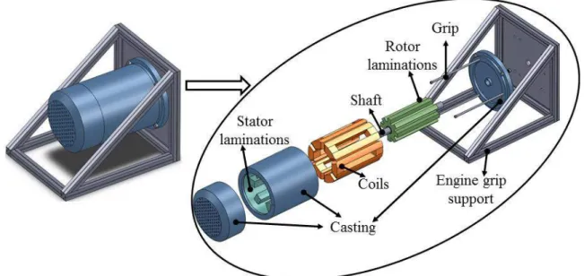
Fig.2.7 Isometric view of the SR machine prototype under study
This SR machine topology is used to validate by numerical simulations and experimental tests the optimization process developed in this thesis. Table 2.1 introduces some design data, more detailed description of design and materials used for the SR machine prototype being found in [9].
Table 2.1 Main design data of the SR machine prototype under study Signification Symbols Value Units
Number of stator teeth 𝑁𝑆 6 -
Number of rotor teeth 𝑁𝑅 8 -
Stator outer diameter 𝐷𝑆𝑒𝑥𝑡 116.6 [mm]
Stator inner diameter 𝐷𝑆𝑖𝑛𝑡 58.25 [mm]
Stator pole width 𝑤𝑆 16 [mm]
Stator yoke width 𝐽𝑆 10 [mm]
Rotor outer diameter 𝐷𝑅𝑒𝑥𝑡 56.55 [mm]
Rotor inner diameter 𝐷𝑅𝑖𝑛𝑡 38 [mm]
Rotor pole width 𝑤𝑅 10.5 [mm]
Rotor yoke width 𝐽𝑅 10 [mm]
Airgap g 0.85 [mm]
Machine axial length 𝑙𝑎 118 [mm]
The number of turns per stator phase is 𝑁𝑠𝑝 = 156, and the electrical resistance of each
phase is 𝑅 = 3.1 Ω. The maximum admissible temperature of the phase windings is 155o C. The SR machine is equipped with Baumer IVO GI321-type encoder having resolution of 600 pulses for recording the rotor position and speed.
2.3. Analytical modeling of the SR machine prototype
The analytical model is applied for a three-phase 6/8 switched reluctance machine topology, i.e having 𝑁𝑆 = 6 stator poles and 𝑁𝑅 = 8 rotor poles that means that the angle
(2𝜋 𝑁⁄ 𝑅) that in this particular case is 45o. The aligned and unaligned positions (fig.2.8) are
characterized as follows [11]:
when the axis of rotor pole and stator excited pole are in the same direction it means that the rotor and stator teeth are aligned (we consider this position θ = 0o in future simulations) (fig.2.8 left)
when the axis of two rotor poles is in the same direction with the axis of one excited stator pole that means the rotor and stator teeth are unaligned (we consider this position θ = 22.5o in future simulations) (fig.2.8 right)
Fig.2.8 Different rotor positions for the SR machine prototype
2.3.1. Analysis of voltage equations
For the simplification when writing the voltage equations we neglect the mutual inductance between phases, this being justified by its lower value, verified by finite elements analyze and measurements on the prototype. We also neglect the effect of fringing flux around the corners and we assume that the flux lines cross the airgap in the radial direction. Instead we consider the material magnetic saturation. Therefore the general stator phase-winding voltage equation of the three-phase 6/8 SR machine under study can be written as shown in eq. 2.3.
𝑢𝑝ℎ = 𝑅 ∙ 𝑖𝑝ℎ+𝑑Ψ𝑝ℎ(𝑖𝑝ℎ, 𝜃)
𝑑𝑡 (2.3) Ψ = 𝐿(𝑖 , 𝜃) ∙ 𝑖
Fig.2.9 Stator-phase equivalent circuit
By neglecting the nonlinear effects of saturation, i.e. assuming magnetic linearity, the SR motor/generator voltage eq. 2.4 can be simplified as:
𝑢𝑝ℎ = 𝑅 ∙ 𝑖𝑝ℎ+ 𝐿(𝜃)𝑑𝑖𝑝ℎ
𝑑𝑡 + 𝑖𝑝ℎ∙ Ω 𝜕𝐿(𝜃)
𝜕𝜃 (2.5) All equations for voltage computation are written for one phase only, for the other phases the same equation is applied. The mathematical computation of the voltage equation can be found in Appendix 2.A.
2.3.2. Instantaneous electromagnetic torque
The instantaneous electric power (Pi) is given by multiplying the voltage equation with the current, therefore when saturation is considered the equation can be written as:
𝑃𝑖,𝑝ℎ = 𝑢𝑝ℎ ∙ 𝑖𝑝ℎ = 𝑅 ∙ 𝑖𝑝ℎ2 + 𝐿(𝜃) ∙ 𝑖 𝑝ℎ∙ 𝑑𝑖𝑝ℎ 𝑑𝑡 + 𝑖𝑝ℎ2 ∙ Ω ∙ 𝑑𝐿(𝜃) 𝑑𝜃 (2.6) At any instant the magnetic stored energy change is given by eq. 2.7.
𝑑 𝑑𝑡( 1 2𝐿(𝜃) ∙ 𝑖𝑝ℎ2 ) = 1 2𝑖𝑝ℎ2 𝑑𝐿(𝜃) 𝑑𝑡 + 𝐿(𝜃) ∙ 𝑖𝑝ℎ 𝑑𝑖𝑝ℎ 𝑑𝑡 =1 2𝑖𝑝ℎ2 ∙Ω∙ 𝑑𝐿(𝜃) 𝑑𝜃 +L(θ)∙𝑖𝑝ℎ 𝑑𝑖𝑝ℎ 𝑑𝑡 (2.7)
The airgap or mechanical power conversion according to energy conversion law 𝑃 = Ω ∙ 𝑇𝑒, is what’s left after resistive losses 𝑅 ∙ 𝑖𝑝ℎ2 and from the input power we can withdraw the
magnetic stored energy, with 𝑇𝑒 being the instantaneous electromagnetic torque. According to
[12] it is possible to write:
𝑇𝑒,𝑝ℎ =1 2𝑖𝑝ℎ2
𝑑𝐿
𝑑𝜃 (2.8) It should be noted that 𝑑𝐿 𝑑𝜃⁄ is the inductance slope presented in chapter 1.
When the nonlinear effect of saturation is considered, the electromagnetic torque developed by the three-phase 6 stator and 8 rotor teeth machine can be expressed in terms of phase magnetic co-energy (presented in chapter 1) as:
𝑇𝑒,𝑝ℎ(𝑖𝑝ℎ, 𝜃) = 𝜕𝑊𝑐,𝑝ℎ 𝜕𝜃 |𝑖𝑝ℎ=cte =𝜕 ∫ 𝐿(𝑖𝑝ℎ, 𝜃) ∙ 𝑖𝑝ℎ∙ 𝑑𝑖 𝑖𝑝ℎ 0 𝜕𝜃 | 𝑖𝑝ℎ=cte (2.9)
During motoring operation, the SR machine produces positive phase electromagnetic torque for the positive phase self-inductance slope at rotor angles between unaligned and the next aligned pole position in the direction of rotation. In generating mode, due to the negative slope of the phase-winding inductance from aligned to unaligned pole position in the direction of rotation, negative phase electromagnetic torque is produced.
2.3.3. Phase inductance vs. rotor position
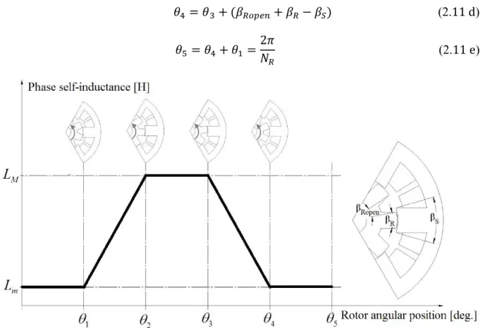
The motional phase back-emf depends on the slope of the phase-winding self-inductance profile with reference to rotor position, which has the ideal shape shown in fig. 2.10. The self-inductance corresponds for one phase when material magnetic saturation and fringe effect are neglected, a representation of it being exemplified in the below figure. This inductance changes with the changing of the number of rotor poles and the width of the stator and rotor teeth. Before computing the angles 𝜃1 to 𝜃5we need to compute the rotor arc opening
𝛽𝑅𝑜𝑝𝑒𝑛.
𝛽𝑅𝑜𝑝𝑒𝑛 =2𝜋 − 𝑁𝑅 ∙ 𝛽𝑅
Fig.2.10 Idealized stator-phase inductance profile vs. rotor position for the three-phase 6/8 SR machine prototype
Fig. 2.10 points out four distinct regions:
0 → θ1 and θ4 → θ5: For the prototype under the study, having an increased number of rotor teeth in respect with stator, a small overlap between rotor and stator teeth appears (see fig. 2.8 Unaligned), this means that the flux lines will be concentrated in the overlap area. Considering that the area of overlapping is small, the torque production between 0 → θ1 and θ4 → θ5 will be small. The inductance in this region is known as unaligned inductance Lu.
θ1 → θ2: The area of overlapping increases, that means that the flux path is
mainly through the stator and rotor laminations. The linear increasing of the overlap area leads to an increase of the inductance, giving it a positive slope. By applying a current in the windings in this period, a positive torque will be produced, i.e motor operation mode. The inductance increase period ends when the overlap is complete.
θ2 → θ3: During this interval the area of overlapping is constant, that means that the path of the dominant flux is the same, leading to a constant maximum inductance, being known as aligned inductance La. For this interval the torque
generation is zero even if remnant current may be found in the phase during this area. This interval provides the necessary time for the current to decrease. θ3 → θ4: In this interval the area of overlapping starts to decrease, i.e the rotor
teeth are starting to come out from the aligned position. This area is similar with the region θ1 → θ2 but opposite, meaning that the inductance starts to decrease
having a negative slope. When applying a current in this area the electromagnetic torque produced will be negative i.e SR machine works in generator operation mode.
The representation from fig. 2.10 is pure informative, because in reality the phase inductance does not have this ideal form due to the saturation effect, which rounds the inductance curve near the top. The values of the angles 𝜃1 to 𝜃5 applied for this prototype can
be found in Appendix 2.B.
The analytical procedure for calculating the aligned and unaligned inductance for this specific configuration is done by determining the flux path in the two rotor position, when the tooth is aligned and when the rotor is perfectly unaligned with the stator excited one. The next paragraph presents step by step the calculation of the inductance profile.
2.3.3.1. Analytical calculation of the phase inductance for aligned rotor position
The computation of the inductance in the aligned position is simple due to the majority of the flux lines, 90% to 98% of them crossing the airgap in the radial direction [13]. Considering the flux plot for the three-phase six stator eight rotor teeth SR machine shown in fig. 2.11, it can be seen that the majority of the flux lines follow path 1 and one small part follow path 2.
Stator tooth path1
𝑙𝑆𝑝1= ℎ𝑆 (2.14)
𝐴𝑆𝑝1= 𝛽𝑆
𝐷𝑆𝑖𝑛𝑡
2 𝑙𝑎 (2.15) Rotor tooth path1
𝑙𝑅𝑝1= ℎ𝑅 (2.16)
𝐴𝑅𝑝1 = 𝛽𝑅(𝐷𝑆𝑖𝑛𝑡
2 − 𝑔) 𝑙𝑎 (2.17) Stator yoke path1
𝑙𝑆𝑦1= 𝜋(𝐷𝑆𝑖𝑛𝑡+ ℎ𝑆+ 𝑤𝑆𝑦)
2 (2.18) 𝐴𝑆𝑦1= 𝑤𝑆𝑦∙ 𝑙𝑎 (2.19) Rotor yoke path1
𝑙𝑅𝑦1 = 𝜋 2( 𝐷𝑆𝑖𝑛𝑡 4 − 𝑔 − ℎ𝑅+ 𝐷𝑅𝑖𝑛𝑡 2 ) (2.20) 𝐴𝑅𝑦1 = (𝐷𝑆𝑖𝑛𝑡 2 − 𝑔 − ℎ𝑅) 𝑙𝑎 (2.21) Having the equations that allow to compute the length and area for each segment in the flux path1 next we can calculate the reluctance for all segments.
𝑅𝑔1= 𝑙𝑔1
𝜇0𝐴𝑔1 (2.22) 𝑅𝑆𝑝1 = 𝐻𝑆𝑝1𝑙𝑆𝑝1
𝑅𝑅𝑝1 = 𝐻𝑅𝑝1𝑙𝑅𝑝1 𝐵𝑅𝑝1𝐴𝑅𝑝1 (2.24) 𝑅𝑆𝑦1 = 𝐻𝑆𝑦1𝑙𝑆𝑦1 𝐵𝑆𝑦1𝐴𝑆𝑦1 (2.25) 𝑅𝑅𝑦1 = 𝐻𝑅𝑦1𝑙𝑅𝑦1 𝐵𝑅𝑦1𝐴𝑅𝑦1 (2.26)
With the reluctance in each segment one can easily calculate the flux and inductance in path1 as follows: Ψ𝑎1 = 𝑁𝑠𝑝∙ 𝑖𝑝ℎ 2(𝑅𝑆𝑝1+ 𝑅𝑔1+ 2𝑅𝑅𝑝1) +12 𝑅𝑅𝑦1+12 𝑅𝑆𝑦1 (2.27) 𝐿𝑎1 =𝑁𝑠𝑝Ψ𝑎1 𝑖𝑝ℎ (2.28) The length and area of the flux path2 is calculated as shown below, for which the magnetic flux density is concentrated at a radius of ℎ𝑆⁄ and an angle of 𝜋 24 ⁄ .
Air-gap path2 𝑙𝑔2= 3ℎ𝑆 4 𝜋 2 (2.29) 𝐴𝑔2= 3ℎ𝑆 4 𝑙𝑎 (2.30) Stator tooth path2
𝑙𝑆𝑝2= 1 2 3ℎ𝑆 4 + 𝑤𝑆𝑦 2 (2.31) 𝐴𝑆𝑝2= 1 2 ( 3ℎ𝑆 4 𝑙𝑎) (2.32) Stator yoke path2
𝑙𝑆𝑦2≅ 𝑙𝑆𝑝2 (2.33)
teeth are identical with the axes of the stator tooth excited. As for the aligned position the reluctance in different segments is calculated 𝑅𝑆𝑝, 𝑅𝑆𝑦, 𝑅𝑅𝑦 and 𝑅𝑔 for the different flux paths
as shown in fig. 2.12.
Fig.2.12 Identification of magnetic flux paths for analytical calculation of the phase inductance for unaligned rotor position
The area and the length of the flux path1 are calculated as one quarter of the stator pole arc. Fig. 2.13 shows the first flux path and fig. 2.14 presents the equivalent circuit for the path1 for the fully unaligned position.
Fig.2.13 Magnetic flux path1 for unaligned rotor position
Fig.2.14 Equivalent circuit and simplified circuit of the magnetic flux path1 for unaligned rotor position Air-gap path1 𝑙𝑔1 = 𝐷𝑆𝑖𝑛𝑡 2 − 𝑔 − ℎ𝑅 (2.38) 𝐴 = 2 ∙ 𝜃 (𝐷𝑆𝑖𝑛𝑡− 𝑔 − ℎ ) 𝑙 (2.39)
Stator yoke path1
𝑙𝑆𝑦1=
𝜋(𝐷𝑆𝑖𝑛𝑡 + 2ℎ𝑆 + 𝑤𝑆𝑦)
2 (2.44) 𝐴𝑆𝑦1= 𝑤𝑆𝑦∙ 𝑙𝑎 (2.45) Rotor yoke path1
𝑙𝑅𝑦1= 𝜋 ( 𝐷𝑅𝑖𝑛𝑡 4 + 𝐷𝑆𝑖𝑛𝑡 4 − 𝑔 2− ℎ𝑅 2) (2.46) 𝐴𝑅𝑦1 = (𝐷𝑆𝑖𝑛𝑡 2 − 𝑔 − ℎ𝑅− 𝐷𝑅𝑖𝑛𝑡 2 ) 𝑙𝑎 (2.47) In these segments the reluctance can be calculated as shown in eqs. 2.22, 2.23 and 2.25 applied for their specific length and areas determined above. The flux and inductance result:
Ψ𝑢1= 𝑁𝑠𝑝∙ 𝑖𝑝ℎ 2𝑅𝑆𝑝1+ 2𝑅𝑔1+𝑅𝑆𝑦12 +𝑅𝑅𝑦12 (2.48) 𝐿𝑢1 = 𝑁𝑠𝑝Ψ𝑢1 𝑖𝑝ℎ (2.49)
In the calculation of the flux path in path2 it is assumed that the flux lines come out from the stator teeth at 645 𝛽𝑆 and enter in the rotor tooth at ℎ4𝑅, therefore the arc of the flux path is considered to be 483 𝛽𝑆. The magnetic equivalent circuit of the flux path2 is presented in fig. 2.15 right and fig. 2.15 left presents the flux line in path2.
Fig.2.15 Magnetic flux path2 (left) and equivalent (right) circuit for unaligned rotor position
Air-gap path2 𝑂𝐷 = (𝐷𝑆𝑖𝑛𝑡 2 − 𝑔 − ℎ𝑅 4) (2.50) 𝐶𝐷 = (𝐷𝑆𝑖𝑛𝑡 2 − 𝑔) 𝛽𝑅 2 (2.51) 𝑂𝐵 =𝐷𝑆𝑖𝑛𝑡 2 (2.52) 𝜃1 = (𝛽𝑆 2 − 5 64𝛽𝑆) (2.53) 𝜃6 = 𝐶𝐷 𝑂𝐷 (2.54) 𝜃7 = 𝜃𝑟𝑝− 𝜃6 (2.55)
The coordinates of B and C can be calculated with eqs. 2.56 and 2.57 respectively. 𝐵 = (𝑥1, 𝑦1) = [(𝑂𝐵)sin𝜃1, (𝑂𝐵)cos𝜃1] (2.56) 𝐶 = (𝑥2, 𝑦2) = [(𝑂𝐷)sin𝜃7, (𝑂𝐷)cos𝜃7] (2.57) 𝐵𝐶 = √(𝑥2− 𝑥1)2+ (𝑦 2− 𝑦1)2 (2.58) 𝑙𝑔2= 𝐵𝐶 (𝜋 3) (2.59)
𝑙𝑆𝑦2≅ 𝑙𝑆𝑦1 (2.65) 𝐴𝑆𝑦2 ≅ 𝐴𝑆𝑦1 (2.66) Rotor yoke path2
𝑙𝑅𝑦2 ≅ 𝑙𝑅𝑦1 (2.67) 𝐴𝑅𝑦2 ≅ 𝐴𝑅𝑦1 (2.68) Ψ𝑢2 = 𝑁𝑠𝑝∙ 𝑖𝑝ℎ 2(𝑅𝑆𝑝2+ 𝑅𝑔2+ 𝑅𝑅𝑝2) + 𝑅𝑆𝑦2+ 𝑅𝑅𝑦2 (2.69) 𝐿𝑢2 = 2𝑁𝑠𝑝Ψ𝑢2 𝑖𝑝ℎ (2.70) When calculating the flux path3, the considerations are like in aligned position because one small part of the rotor tooth overlaps the stator. Fig. 2.16 represents the flux lines that cross the stator and the rotor in the overlapped segment.
Air-gap path3 𝑙𝑔3 = 𝑔 (2.71) 𝜃1 = 𝛽𝑆− 𝛽𝑅𝑜𝑝𝑒𝑛 2 (2.72) 𝐴𝑔3= 𝜃1 𝐷𝑆𝑖𝑛𝑡 2 𝑙𝑎+ 𝜃1(𝐷𝑆𝑖𝑛𝑡2 − 𝑔) 𝑙𝑎 2 (2.73) Stator tooth path3
𝑙𝑆𝑝3= ℎ𝑆 (2.74) 𝐴𝑆𝑝3= 𝜃1𝐷𝑆𝑖𝑛𝑡
2 𝑙𝑎 (2.75) Rotor tooth path3
𝑙𝑅𝑝3= ℎ𝑅 (2.76)
𝐴𝑅𝑝3 = 𝜃1(𝐷𝑆𝑖𝑛𝑡
2 − 𝑔) 𝑙𝑎 (2.77) Stator yoke path3
𝑙𝑆𝑦3≅ 𝑙𝑆𝑦1 (2.78)
𝐴𝑆𝑦3 ≅ 𝐴𝑆𝑦1 (2.79)
Rotor yoke path3
𝑙𝑅𝑦3 ≅ 𝑙𝑅𝑦1 (2.80) 𝐴𝑅𝑦3 ≅ 𝐴𝑅𝑦1 (2.81) Ψ𝑢3= 𝑁𝑠𝑝∙ 𝑖𝑝ℎ 2(𝑅𝑆𝑝3+ 𝑅𝑔3+ 𝑅𝑅𝑝3) + 𝑅𝑆𝑦3+ 𝑅𝑅𝑦3 (2.82) 𝐿𝑢3 = 2𝑁𝑠𝑝Ψ𝑢3 𝑖𝑝ℎ (2.83)
Fig.2.17 Magnetic flux path4 for unaligned rotor position Air-gap path4 𝑥1 = 𝐴𝐵 = 𝐷𝑆𝑖𝑛𝑡 2 sin ( 𝛽𝑆 2) (2.84) 𝑦1 = 𝑂𝐴 = 𝐷𝑆𝑖𝑛𝑡 2 cos ( 𝛽𝑆 2) + ℎ𝑆 (2.85) The coordinates of B can be calculated as follows:
𝐵 = (𝑥1, 𝑦1) (2.86) 𝜃1 = tan−1( 𝑥1 𝐴𝐷) = tan−1( 𝑥1 𝑦1− (𝐷𝑆𝑖𝑛𝑡 2 − 𝑔 − ℎ𝑅) ) (2.87) 𝑂𝐶 = (𝐷𝑆𝑖𝑛𝑡 2 − 𝑔) (2.88) 𝜃2 = (𝜃𝑟𝑝 2 − 5 64𝛽𝑅) (2.89) Further the coordinates of C and D can be calculated with the help of eqs. 2.90 and 2.91
𝐶 = (𝑥2, 𝑦2) = [(𝑂𝐶) sin(𝜃2) , (𝑂𝐶)cos (𝜃2)] (2.90)
𝐷 = (𝑥3, 𝑦3) = [0, (𝐷𝑆𝑖𝑛𝑡2 − 𝑔 − ℎ𝑅)] (2.91) 𝐷𝐶 = √(𝑥3− 𝑥2)2+ (𝑦3− 𝑦2)2 (2.92)
𝜃3 = tan−1( 𝐶𝐸 𝐷𝐸) = tan−1( 𝑦2− 𝑦3 𝑥2 ) (2.94) 𝜃4 = 𝜋 2− 𝜃3− 𝜃1 (2.95) 𝑙𝑔4 = 1 2(𝐷𝐵 + 𝐷𝐶)𝜃4 (2.96) 𝐴𝑔4= 1 2(𝐴𝑆𝑝4+ 𝐴𝑅𝑝4) (2.97) Stator tooth path4
𝑙𝑆𝑝4= ℎ𝑆 (2.98)
𝐴𝑆𝑝4= 3 4
ℎ𝑆
4 𝑙𝑎 (2.99) Rotor tooth path4
𝑙𝑅𝑝4= ℎ𝑅 (2.100) 𝐴𝑅𝑝4 = ( 𝐷𝑆𝑖𝑛𝑡 2 − 𝑔) 𝛽𝑅 8 𝑙𝑎 (2.101) Stator yoke path4
𝑙𝑆𝑦4 ≅ 𝑙𝑆𝑦1 (2.102) 𝐴𝑆𝑦4≅ 𝐴𝑆𝑦1 (2.103) Rotor yoke path4
𝑙𝑅𝑦4 ≅ 𝑙𝑅𝑦1 (2.104) 𝐴𝑅𝑦4 ≅ 𝐴𝑅𝑦1 (2.105) Ψ𝑢4= 𝑁𝑠𝑝∙ 𝑖𝑝ℎ 2(𝑅𝑆𝑝4+ 𝑅𝑔4+ 𝑅𝑅𝑝4) + 𝑅𝑆𝑦4+ 𝑅𝑅𝑦4 (2.106) 𝐿𝑢4 = 2 𝑁𝑠𝑝Ψ𝑢4 𝑖𝑝ℎ (2.107)
Fig.2.18 Magnetic flux path5 and magnetic equivalent circuit for unaligned position Air-gap path5 𝑙𝑔5=ℎ𝑆 4 𝜋 2 (2.108) 𝐴𝑔5= 𝐴𝑆𝑝5 (2.109)
Stator tooth path5
𝑙𝑆𝑝5=
ℎ𝑆
4 (2.110) 𝐴𝑆𝑝5= ℎ𝑆
2 𝑙𝑎 (2.111) Stator yoke path5
𝑙𝑆𝑦5≅ℎ𝑆 4 + 𝑤𝑆𝑦 4 (2.112) 𝐴𝑆𝑦5= 𝐴𝑆𝑦1 (2.113) Ψ𝑢5= 𝑁𝑠𝑝∙ 𝑖𝑝ℎ 2𝑅𝑆𝑝5+ 𝑅𝑔5+ 𝑅𝑆𝑦5 (2.114) 𝐿𝑢5= 2 𝑁𝑠𝑝Ψ𝑢5 𝑖𝑝ℎ (2.115)
The unaligned inductance known as the minimum inductance represents the sum of all inductances calculated for each flux path
𝐿𝑚 = ∑ 𝐿𝑢𝑗
5
𝑗=1
(2.116)
The entire calculation of the maximum and minimum inductance applied for the nominal current of the SR machine prototype (4A) can be found in Appendix 2.B. Yet, a
comparison in terms of results obtained analytically and FE computation of the aligned and unaligned inductance can be found in the next paragraphs.
2.4. Validation of the analytical model by finite-element magnetic field analysis Validation by finite element (FE) field analysis is useful in order to predict the accuracy of the analytical model. The current in phase when applying a constant DC voltage, the electromagnetic torque when suppling one phase and rotate the machine at a constant speed as well as the phase inductances for aligned and unaligned rotor positions are validated by means of FE software.
2.4.1. Finite element software used for validation
The finite element software used for validation is JMAG Designer, this is a FE software at the core of JMAG that is used to develop and design electrical components. The first appearance of JMAG was in 1983, built to support the design of the devices such as motors, actuators and circuits. Many versions appeared over the time, the last one is JMAG Designer 15.1 released in 2016 [14]. Many features were improved over the years such as: parallel solver performance, some practical functions were added, etc.
2.4.2. Comparative FE-computed and analytical results
By using the JMAG-Designer software, several magnetic field FE analyses in the cross-section of the three-phase 6/8 SR machine (fig. 2.19) have been carried out in order to plot the stator phase-winding self-inductance variation and electromagnetic torque in respect of rotor angular position for different phase current strengths. When implementing the geometry in FE software the parameters used were those from table 2.1 and copper was set as material for the coils whilst for the stator and rotor the material curve is the one presented in [9].
Fig.2.19 FE-discretized cross-section geometry of the three-phase 6/8 SR machine under study
A cartography map of the inductance evolution with the rotor position for different values of phase current strength is presented in fig. 2.20. These waveforms were realized in FE software by suppling one phase with constant current for different values and engaging the rotor in motion at constant speed for one mechanical period (2𝜋 𝑁⁄ 𝑅).
Fig.2.20 Stator-phase self-inductance of the three-phase 6/8 SR machine as a function of stator-phase current strength and rotor angular position.
2.4.2.1. Validation of the voltage equations
By solving the SRM/G phase-voltage eq. 2.4, one obtains the time-variation of the phase current strength. When calculating eq. 2.4 the evolution of the phase inductance with the rotor position and current was taken the one from fig. 2.20. Fig. 2.21 displays comparative
FE-computed and analytically-calculated results for the time-variation of the stator-phase current strength in the steady-state of the three-phase 6/8 SR machine under study, at constant rotor speed and for two values of the energizing DC-link voltage, i.e. 8V and 15V, respectively. As assessed outcome of this comparison, the average value of the phase current strength obtained from FE-computed results is with 1.1% lower than that determined analytically, for the case of 8V and 15V energizing DC-link voltage.
Fig.2.21 Comparative FE-computed and analytically-calculated results for the time-variation of the stator-phase current strength in the steady-state of the three-phase 6/8 SR machine, for constant rotor
speed and two values of DC-link voltage
When obtaining the waveforms of fig. 2.21, one phase was energized with constant DC voltage and the rotor was engaged in motion at constant speed. The increase and decrease of the current in the phase is given by the evolution of the inductance as a function of the rotor position, i.e. in the positive slope of the inductance the phase current decreases and in the negative slope of the inductance the phase current increases.
2.4.2.2. Validation of electromagnetic torque equations
By solving eq. 2.9, time variation of the electromagnetic torque in both motor and generator operation mode is displayed. Fig. 2.22 highlights comparative evolution of the electromagnetic torque analytically calculated and FE computed.
Fig.2.22 Comparative FE-computed and analytically-calculated results for time variation of electromagnetic torque in steady-state, for constant rotor speed and different values of phase current
The comparison was realized by imposing a constant rotor speed and one phase was energized over one mechanical period. The both alternation of electromagnetic torque indicates that the machine, depending on the rotor position, is able to operate in both motor and generator mode. Therefore when the rotor is starting to come into aligned position with the stator energized one, the electromagnetic torque produced by the machine is positive, i.e. SR machine functions in motor operation mode and when the aligned position is overcome and the stator phase is still energized the electromagnetic torque produced by the machine is negative, i.e. SR machine functions in generator mode.
2.4.2.3. Phase inductance validation
The phase inductance of the studied SR machine changes, its variation depending on the rotor position, but the value of the inductance depends on the geometry of the machine and phase current. For this thesis, the modality of aligned and unaligned inductance calculation detailed in [13], was adapted here for an increased number of rotor teeth. Therefore eqs. 2.12 - 2.116 present in a detailed fashion, the aligned and unaligned inductance determination from the magnetic flux lines paths for a configuration with an increased number of rotor teeth.
Starting from a known geometry, finite elements validation was realized to determine the accuracy of the analytical model. Fig. 2.23 and table 2.2 presents the comparison between FE-computation and analytically-calculated inductances for the aligned and unaligned rotor positions, when changing the current in phase.
Fig.2.23 Comparative FE-computed and analytically-calculated maximum and minimum values of the stator-phase self-inductance of the three-phase 6/8 SR machine
Table 2.2 Comparative FE-computed and analytically-calculated maximum and minimum values of
the stator-phase self-inductance for multiple phase current strength Phase current strength
[A] Rotor position
Analytically calculated inductance [H] FE computed inductance [H] 1 Aligned 0.03627 0.03628 Unaligned 0.0255 0.0255 2 Aligned 0.03655 0.03656 Unaligned 0.0257 0.0257 3 Aligned 0.0366 0.0366 Unaligned 0.02574 0.02574 4 Aligned 0.03668 0.03669 Unaligned 0.0258 0.0258 5 Aligned 0.03668 0.03668 Unaligned 0.0258 0.0258 6 Aligned 0.0366 0.0366 Unaligned 0.0257 0.0257
For both of the rotor positions (aligned and unaligned) the inductance was computed by FE software and analytically for different values of phase current strength. If we take in consideration the values of inductance computed for a phase current strength of 4A, the difference between the values computed by FE analyze and analytically calculated is less than 1%. Given the fact that in computation time the analytical calculation is faster, this approach will be used further in the optimization process. The proximity between the values of the
The SR motor and generator simulation model has been developed and implemented in MATLAB/Simulink environment with the block diagram shown in fig. 2.24. It should be pointed that in motor operation mode a speed control was realized and in generator operation mode a torque control provides the reference current for a given speed.
Fig.2.24 MATLAB/Simulink model of the three-phase 6/8 SR machine for motor and generator operation modes
The simulation modules are the three-phase 6/8 SR machine model, the current control block which realizes a stator current control by hysteresis, considering the reference current provided by the speed control block, inside of which a PI rotor-speed regulation is done. The position sensor block provides the rotor position information for electronic commutation of stator phase currents; this is used for determining the ON and OFF signals to be applied to each specific bridge of the three-phase half-bridge asymmetrical power converter.
A more detailed view of the switched reluctance motor/generator block is pointed in the below part of the figure. The first part presented above incorporates the control of the SR machine and the SRM/G block contains the electrical, electromagnetic and mechanical equations. The data used to realize fig. 2.20 is implemented in a Lookup table and depending on the rotor position and current it provides the real shape of the inductance. Eqs. 2.4 and 2.9 are implemented in the current block respectively torque block. The outputs of the SR machine simulation block are the stator phase currents, the developed electromagnetic torque, the rotor speed and the generated power.
Further application of dynamic simulations using MATLAB/Simulink model together with FE magnetic field analyses enables the control/design of the three-phase 6/8 SR machine to be optimized for motoring and generating operation.
2.5.2. Influence of commutation angles
Studies show that the commutation angles have a great impact in SR machine’s efficiency and the adjustment of the commutation angles can lead to an increased efficiency for this type of machine. A part of the studies in this thesis is dedicated to the effect of the commutation angles on the torque ripple and on the value of mean electromagnetic torque 〈𝑇𝑒〉. 2.5.2.1. Simulations with theoretical angle
For the first set of simulations in motor operation mode, if we consider fig. 2.8 when rotor teeth are aligned with phase1 and we keep the rotation direction, phase3 should be supplied in order for the machine to produce positive torque. For this particular case we can consider 𝜃𝑜𝑛 = 0o and 𝜃𝑜𝑓𝑓 can be calculated with eq. 2.117.
𝜃𝑜𝑓𝑓 = 2𝜋
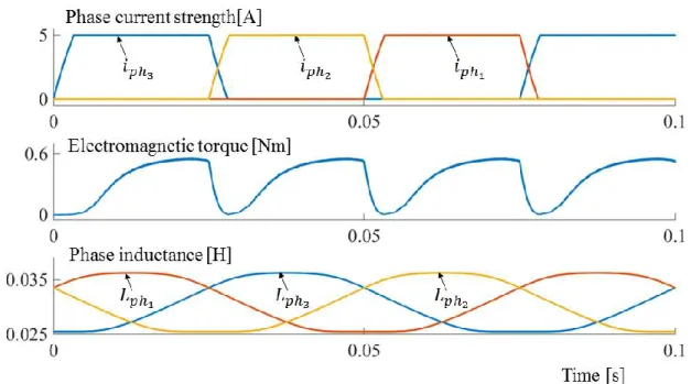
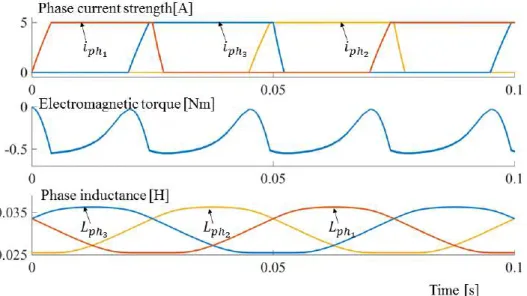
Fig.2.25 Simulated steady-state responses in current, electromagnetic torque and inductance of the three-phase 6/8 SR machine, for motor operation mode
Fig. 2.25 represents the waveforms of the current, electromagnetic torque and inductance of the three-phase 6 stator and 8 rotor teeth switched reluctance machine working in motor operation mode with 𝜃𝑜𝑛 = 0o and 𝜃
𝑜𝑓𝑓 = 15o. As it can be remarked the machine
phases are independent to one another and are in conduction during the positive slope of the inductance, i.e. the moment in which the rotor starts to come into aligned position with the stator excited phase.
By shifting the excitation in the negative slope of the inductance, i.e. rotor teeth are starting to come out from aligned position with the stator excited phase, SR machine will produce negative torque. For the next set of simulations we want to define the angles 𝜃𝑜𝑛 and
𝜃𝑜𝑓𝑓 so that the excitation of the phase to be found in the negative slope of inductance.
Therefore in the calculation of the theoretical angles for the generator operation mode eqs. 2.118 and 2.119 are used.
𝜃𝑜𝑛 = 2𝜋 𝑁𝑅(1 − 1 𝑞) (2.118) 𝜃𝑜𝑓𝑓 = 2𝜋 𝑁𝑅 (2.119)
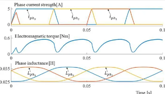
Fig.2.26 Simulated steady-state responses in current, electromagnetic torque and inductance of the three-phase 6/8 SR machine, for generator operation mode
Fig. 2.26 displays the evolution of current, electromagnetic torque and inductance for the three-phase 6/8 SR machine under study in generator operation mode with 𝜃𝑜𝑛 = 30o and
𝜃𝑜𝑓𝑓 = 45o.
To be noted that in the realization of the above figures, the current control by hysteresis was done with a hysteresis band of 0.05A, for a reference current of 5A and the rotor was engaged in motion at constant speed of 100 rpm. The MATLAB/Simulink model used for the above simulations is the one presented in fig. 2.24, but without the speed control block, the reference current being given as a constant value.
2.5.2.2. Simulations when commutation angles change
Having an analytical model of the three-phase 6/8 SR machine implemented in MATLAB/Simulink that is able to be simulated in motor and generator operation mode by changing the commutation angles, next we can try to minimize the torque oscillation and in the same time to increase the mean electromagnetic torque by adjusting the commutation angles for both operation modes (motor and generator).
![Fig. 1.1 World carbon-dioxide emissions by sectors, in 2013 [2]](https://thumb-eu.123doks.com/thumbv2/123doknet/14742202.755301/17.892.227.669.369.636/fig-world-carbon-dioxide-emissions-sectors.webp)