Publisher’s version / Version de l'éditeur:
Journal of Engineering for Gas Turbines and Power, 138, 7, pp.
072503-1-072503-7, 2015-12-04
READ THESE TERMS AND CONDITIONS CAREFULLY BEFORE USING THIS WEBSITE.
https://nrc-publications.canada.ca/eng/copyright
Vous avez des questions? Nous pouvons vous aider. Pour communiquer directement avec un auteur, consultez la
première page de la revue dans laquelle son article a été publié afin de trouver ses coordonnées. Si vous n’arrivez pas à les repérer, communiquez avec nous à PublicationsArchive-ArchivesPublications@nrc-cnrc.gc.ca.
Questions? Contact the NRC Publications Archive team at
PublicationsArchive-ArchivesPublications@nrc-cnrc.gc.ca. If you wish to email the authors directly, please see the first page of the publication for their contact information.
NRC Publications Archive
Archives des publications du CNRC
This publication could be one of several versions: author’s original, accepted manuscript or the publisher’s version. / La version de cette publication peut être l’une des suivantes : la version prépublication de l’auteur, la version acceptée du manuscrit ou la version de l’éditeur.
For the publisher’s version, please access the DOI link below./ Pour consulter la version de l’éditeur, utilisez le lien DOI ci-dessous.
https://doi.org/10.1115/1.4031908
Access and use of this website and the material on it are subject to the Terms and Conditions set forth at
A mechanism-based approach from low cycle fatigue to
thermomechanical fatigue life prediction
Wu, Xijia; Zhang, Zhong
https://publications-cnrc.canada.ca/fra/droits
L’accès à ce site Web et l’utilisation de son contenu sont assujettis aux conditions présentées dans le site LISEZ CES CONDITIONS ATTENTIVEMENT AVANT D’UTILISER CE SITE WEB.
NRC Publications Record / Notice d'Archives des publications de CNRC:
https://nrc-publications.canada.ca/eng/view/object/?id=f4d75b78-d0a6-438f-bb6e-b30a7c15a216 https://publications-cnrc.canada.ca/fra/voir/objet/?id=f4d75b78-d0a6-438f-bb6e-b30a7c15a216A MECHANISM-BASED APPROACH FROM LOW CYCLE FATIGUE TO
THERMOMECHANICAL FATIGUE LIFE PREDICTION
Xijia Wu and Zhong Zhang
National Research Council Canada Ottawa, Ontario, Canada K1A 0R6
ABSTRACT
Deformation and damage accumulation occur by fundamental dislocation and diffusion mechanisms. An integrated creep-fatigue theory (ICFT) has been developed, based on the physical strain decomposition rule that recognizes the role of each deformation mechanism and thus relate damage accumulation to its underlying physical mechanism(s). The ICFT formulates the overall damage accumulation as a holistic damage process consisting of nucleation and propagation of surface/subsurface cracks in coalescence with internally distributed damage/ discontinuities. These guiding principles run through both isothermal low cycle fatigue (LCF) and thermomechanical fatigue (TMF) under general conditions.
This paper presents a methodology using mechanism-based constitutive equations to describe the cyclic stress strain curve and the non-linear damage accumulation equation incorporating i) rate-independent plasticity-induced fatigue, ii) intergranular embrittlement, iii) creep and iv) oxidation to predict LCF and TMF lives of ductile cast iron (DCI). The complication of the mechanisms and their interactions in this material provide a good demonstration case for the model, which is in good agreement with the experimental observations.
NOMENCLATURE
ac—critical crack length;
d—cellular cell size or grain size; da/dN—crack growth rate; D—internal damage factor; E—elastic modulus;
h—newly-formed oxide scale thickness per cycle; k—parabolic oxidation constant;
KIC—fracture toughness;
N—cycles to failure;
Nf—mechanical fatigue life;
Y—crack shape factor;
α— coefficient of thermal expansion; ε—total strain; ε'f—fatigue ductility; εth—thermal strain; εp—plastic strain; εv—creep strain; η—constraint ratio; σ—stress. INTRODUCTION
Thermomechanical fatigue (TMF) is the major failure mode of engineering components such as gas turbine nozzle guide vanes, blades, and automotive exhaust manifolds, etc. operating under thermal-mechanical loading. It is a great challenge for component designers to predict the component TMF life based on limited material testing data, since the combinations of thermal and mechanical loads, with or without superimposed dwells, in service are
range), mechanical strain range and strain rate, and thermal-mechanical phase angle could all influence the TMF behavior of a material. It would be quite expensive to perform an exhaustive test matrix to evaluate the effects of all these factors, but it is important to understand them in engineering design. Therefore, it is desirable to develop physics-based methods that warrant TMF life prediction with the knowledge obtained from simple standard tests and the ease of implementation in the finite element method (FEM) for component analysis.
TMF stress analysis and life prediction need to employ constitutive and damage equations covering a plethora of deformation mechanisms operative over the temperature range of application. It has been recognized that rate-independent plasticity proceeds by crystallographic slip, which leads to fatigue crack nucleation and propagation under cyclic loading; whereas dislocation climb plus glide results in creep, which produce internally distributed damage in the form of creep cavities and grain boundary microcracks etc. [1-4]. For understanding the physics of failure, it is important to relate the accumulation of specific damage with respect to its underlying deformation and damage mechanism. The overall damage accumulation can be considered as a holistic process consisting of nucleation and propagation of surface/subsurface fatigue cracks in coalescence with internally distributed damage or discontinuities as promoted by creep/dwell and intergranular embrittlement [5, 6].
In this regard, the unified constitutive theory [7, 8] formulates deformation as a total viscoplastic quantity with no delineation of mechanism-strains. Continuum damage mechanics [9, 10] employs a damage parameter ω with values from 0 to 1 to represent the material’s damage state with no specification of intragranular or intergranular failure. The linear summation rule [11] is often used to account for damage accumulation involving multiple damage mechanisms, but it is lacking a physical basis.
This paper uses the integrated creep-fatigue theory (ICFT) [4-6] to analyze the LCF and TMF behaviors of DCI
at different strain rates from 0.0002/s to 0.02/s in the temperature range from room temperature (RT) to 800oC. It
emphasizes life prediction with quantitative delineation of all the contributing deformation/damage mechanisms. It proves that ICFT can not only provide an accurate description of the macroscopic constitutive and life behaviors with respect to the dominant mechanisms, but also sheds light to material design choices, thereby limiting/suppressing the undesired material failure mode.
THE THEORETICAL FORMULATION
By physical strain decomposition, the total strain is the sum of elastic strain, plastic strain εpand viscous (creep)
strain εv, as: v p E
(1)Rate-independent plasticity with kinematic and isotropic hardening follows the classical constitutive theory:
n p
K
0
(2)where n and K are temperature-dependent material constants, σ0defines the initial yield surface.
Creep deformation can be further decomposed into intragranular deformation (ID) and grain boundary sliding (GBS) [12, 13], but here considering that DCI contains a cellular network of eutectic phase of (Fe, Mo, Si) C along the grain boundaries, which suppresses GBS, only the power-law creep is manifested:
m v
A
(3)where A is an Arrhenius constant, and m is the power-index.
Both plasticity and creep algorithms are adopted by commercial FEM software such as Abaqus and MSC.Marc. Hence, the material coupon behavior can be simulated using a one-element FEM model, and mechanism-strains are obtained from the output.
Considering the holistic damage accumulation process as nucleation and propagation of surface/subsurface fatigue cracks in coalescence with internally distributed damage, the overall damage accumulation rate, da/dN, has been derived as [5]: ox f dN da dN da D dN da (4) where (da/dN)fis the fatigue contribution, (da/dN)ox is the oxidation contribution; D is the knockdown factor by internally distributed damage; when multiple forms of internal damage/discontinuities are present, D can be expressed as:
i i i l D 1 (5)where liis the internal crack/cavity size and λiis the inter-spacing of the ithcomponent of damage.
For DCI, two types of internal damage have been included in Eq. (5): i) intergranular embrittlement (IE) at
medium temperature ~400oC, and ii) nodular void growth by creep, such that (for details, see [6]):
v
d
D
1
(6)where d is the eutectic cellular size, λ is its thickness, ϕ is the intergranular embrittlement factor, and β is the nodular void growth factor.
Finally, when the dominant crack grows to a critical crack length, ac, fracture occurs. Integration of Eq. (4) in an
average sense leads to: c f a h N D N 1 1 (7)
where h (h 2k, is the cycle period) is the thickness of newly-formed oxide scale per cycle, and the critical
crack length is defined by fracture mechanics, as: 2 max 1 Y K ac IC (8)
In Eq. (7), the fatigue life follows the Coffin-Manson relationship (related to pure plasticity) as:
c f f p
N
2
(9)The damage accumulation equation, in the context of Eq. (7), implies the physical rationale that fatigue damage proceeds by plasticity via irreversible slip, while creep and IE produces internally distributed damage. Particularly, creep deformation arises mainly due to dislocation climb that releases pile-up dislocations at the obstacles in glide, and because of the random nature of vacancy flow, dislocation climb would ease slip concentration, thus not directly contributing to fatigue damage. Then, Eq. (7) naturally encompasses both transgranular (mechanical fatigue) and intergranular (IE and creep) fracture.
RESULTS AND DISCUSSION
1) LCF
The cyclic stress-strain curves of DCI at various temperatures are shown in Figure 1, in a normalized fashion. The plasticity constants K and n were determined at room temperature (RT), and they were used to evaluate plasticity at other temperature conditions (note that K is proportional to the elastic modulus as implied in the
Ramberg-Osgood relationship). It turned out that deformation at 400oC was also predominantly rate-independent, as
exhibited in the tests and evaluated using the model. The cyclic stress-strain relationships at 600oC and 800oC exhibited significant rate-dependency, and the model describes that by incorporation of power-law creep. It can be seen that deformation of DCI at high temperatures >600oC proceeds predominantly by creep without hardening. Then, the question is what are the respective contributions of plasticity and creep in LCF life?
a) 0 0.1 0.2 0.3 0.4 0.5 0.6 0.7 0.8 0.9 1 0 0.2 0.4 0.6 0.8 1 1.2 St re ss A m pl it u d e (N o rm al iz ed ) Strain Amplitude, %
RT
Prediction Exp.(0.02/s) Exp. (0.002/s)b) 0 0.1 0.2 0.3 0.4 0.5 0.6 0.7 0.8 0 0.2 0.4 0.6 0.8 1 1.2 St re ss A m pl itu de (N or m al iz ed ) Strain Amplitude, %
400
oC
Prediction Exp.(0.02/s) Exp. (0.002/s) Exp. (0.0002/s) c) 0 0.05 0.1 0.15 0.2 0.25 0.3 0.35 0.4 0 0.2 0.4 0.6 0.8 1 1.2 St re ss A m pl it ud e (N or m al iz ed ) Strain Amplitude, % 600 oC Prediction (0.02/s) Prediction (0.0002/s) Exp. (0.02/s) Exp. (0.0002/s) d) -0.01 0.01 0.03 0.05 0.07 0.09 0.11 0.13 0.15 0 0.2 0.4 0.6 0.8 1 1.2 St re ss A m pl itu de (N or m al iz ed ) Strain Amplitude, %800
oC
Prediction (0.02/s) Prediction (0.002/s) Prediction (0.0002/s) Exp. (0.02/s) Exp. (0.002/s) Exp. (0.0002/s)Figure 1. Cyclic stress-strain curve for DCI at a) RT, b) 400oC, c) 600oC, and d) 800oC.
0.1 1 10 0.000001 0.00001 0.0001 0.001 0.01 0.1 1 10 To ta l S tr ai n Am pl itu de (% )
Normalized Fatigue Life RT (All) 400C (All) 600C (0.02/s) 600C(0.0002/s) 800C (0.02/s) 800C(0.0002/s) Model (RT) Model (400C) Model (0.02/s@600C) Model(0.0002@600C) Model (0.02/s@800C) Model(0.0002/s@800C)
The observed LCF life behaviour (symbols) and model description (lines) under various test conditions are shown in Figure 2, in a normalized fashion. For RT-LCF, Eq. (7) reduces to the Coffin-Manson relationship, Eq. (9), because IE (), creep (v) and oxidation are all null. At 400oC, the fatigue life was significantly reduced by IE,
almost uniformly at all strain levels, because reached its maximum and the fracture surfaces predominantly
consisted of grain boundary facets [6]. What is interesting is that at high temperatures (>600oC) the material
exhibited cross-over behaviour relative to the RT curve, and the LCF life at 800oC was consistently higher than that
at 600oC. These phenomena could not be explained by the conventional damage summation rule. First of all, if the
total inelastic strain (plasticity plus creep, or the viscoplastic strain in the “unified” sense) were responsible for fatigue, then by reasoning with the Coffin-Mansion relationship, LCF at higher temperature would always have a shorter life than at lower temperature, because at the same total strain level inelastic strain contribution would become larger as the elastic strain was reduced. Second of all, the linear damage summation rule would infer that LCF at high temperatures involving creep and oxidation would have shorter life than that at RT, because those contributions would add positively in a linear fashion. The ICFT describes these phenomena with quantitative delineation of the creep-plasticity interaction in a non-linear fashion. The onset of creep deformation taking over plasticity does not directly contribute to fatigue, but rather has an effect to enlarge the internal damage of the material. Furthermore, the onset of creep lowers the flow stress, which enables the coupon to tolerate a longer crack, according to Eq. (8). Then, the competition of oxidation and creep is in play, as the ratio h/ac matters for
high-temperature LCF. The intricate fatigue-creep-oxidation interaction may be better summarized in the LCF mechanism
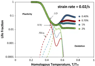
map, as shown in Figure 3 of life fractions (N/Nf for fatigue, and Nh/ac for oxidation) vs. the homologous
temperature (T/Tm, where Tmis the melting temperature in Kelvin). The circle-connected curves show the overall
effect of the internal damage factor D. At temperatures below 250oC, it virtually has no effect, while the total life is
almost exclusively comprised of mechanical fatigue by rate-independent plasticity. As temperature increases, the effect of IE increases sharply, reaching a maximum at ~400oC. Above 400oC, the effect of internal damage is gradually taken over by creep, and at the same time the oxidation life fraction, Nh/ac, rises up to dominance.
Interestingly, Nh/ac approaches a constant level as temperature increases at a given cyclic strain level. The LCF
mechanism map basically indicates that a material exhibiting clean creep (producing minimal cavities) and having good oxidation resistance will have an enhanced LCF resistance at high temperature. The LCF map provides a quantitative means for performance optimization in material design and life prediction.
2) TMF
One type of TMF experiment is to control mechanical strain and temperature independently but with a phase
angle between the two loading waves. Out-of-phase (OP, =180o) TMF resulted in hysteresis behaviours as
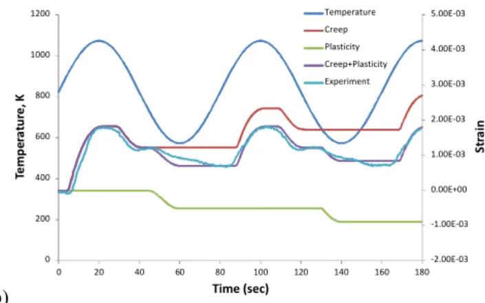
shown in Figure 4a for DCI in the temperature range of 300-800oC. The ICFT model not only simulates the
stress-strain behaviour but also delineates plastic and creep stress-strains, as shown in Figure 4a and 4b. As expected, creep deformation dominated during the “hot” part of the cycle in compression, and plastic strain arose during the “cold’’ part of the cycle in tension. The two components add up as the total inelastic strain, in good comparison with the
experimental observation. In-phase (IP, = 0o) TMF resulted in hysteresis behaviours in the reverse sense of OP for
Figure 3. LCF mechanism map for DCI at strain rate of 0.02/s.
Another type of TMF experiment is the constrained TMF, where only temperature is controlled and deformation
is constrained at a constant constraint ratio as defined by
th tot th
(10)The constraint ratio is a thermal-structural property that reflects the constraint of thermal expansion due to thermal gradient and structural design. The hysteresis behavior of DCI under 100% constraint TMF with a dwell
period of 1 min. in the temperature range of 160-600oC is shown in Figure 6a, and the accumulation of plastic and
creep strains during this TMF cycle is shown in Figure 6b. Again, the ICFT simulation describes well the hysteresis behaviour, as well as the strain accumulation with time.
In actual engineering components, materials are subject to various degrees of constraint. By nature, the constrained mechanical strain is out-of-phase with the thermal loading. If mechanical loading is also applied independently, the thermomechanical cycle can be quite complicated. Therefore, it is important to faithfully simulate the deformation and life behaviours and damage modes for all TMF combinations. The mechanism-based approach offers the solution.
a) -200 -100 0 100 200 300 400 500 -0.003 -0.002 -0.001 0.000 0.001 0.002 0.003 st re ss (M Pa ) mechanical strain OP 300-800oC Prediction Exp. 1st cycle Exp. Mid life
b) -3.00E-03 -2.00E-03 -1.00E-03 0.00E+00 1.00E-03 2.00E-03 3.00E-03 0 200 400 600 800 1000 1200 0 20 40 60 80 100 120 140 160 180 St ra in Te m pe ra tu re , K Time (sec) Temperature Creep Plasticity Creep+Plasticity Experiment
Figure 4. The hysteresis behaviour, a) and b) strain accumulation during OP-TMF in the range of 300-800oC.
For TMF life prediction Eq. (7) also holds valid, except that the IE factor is taken by average, and the oxide scale thickness h is evaluated by integration over the TMF cycle period. In addition, there is generally a mismatch stress between the oxide scale and the base metal. By strain compatibility, the thermal mismatch modified substrate stress is given by:
)] )( ( [ ) 1 ( s ox s ox r ox s s fE f E fE T T E (11)
where σ is the specimen nominal stress; Tris the reference temperature at which the oxide forms without mismatch;
Esand Eox, and αsand αoxare the elastic modulus and the coefficient of thermal expansion (CTE) of the substrate
(DCI) and the oxide, respectively; and f is the areal fraction of the oxide. Evidently, under isothermal conditions, the
mismatch is always zero, because T = Tr. However, under TMF conditions, the effect becomes maximal for
out-of-phase (OP) TMF, since the film forms at “hot” temperatures but breaks in “cold”; whereas it becomes minimal for in-phase (IP) TMF, since the film-breaking temperature is the same as the formation temperature.
a) -500 -400 -300 -200 -100 0 100 200 -0.003 -0.002 -0.002 -0.001 -0.001 0.000 0.001 0.001 0.002 0.002 0.003 st re ss (M Pa ) mechanical strain IP 300-800oC Prediction Exp. 1st cycle Exp. Mid-life
b) -2.00E-03 -1.00E-03 0.00E+00 1.00E-03 2.00E-03 3.00E-03 4.00E-03 5.00E-03 0 200 400 600 800 1000 1200 0 20 40 60 80 100 120 140 160 180 St ra in Te m pe ra tu re , K Time (sec) Temperature Creep Plasticity Creep+Plasticity Experiment
Figure 5. The hysteresis behaviour, a) and b) strain accumulation during IP-TMF in the range of 300-800oC.
By mechanical and metallurgical arguments, alternating plasticity contributes to fatigue, but only forward creep strain (proceeding towards tension from the previous deformation state) facilitates void growth. Figure 7 shows the model prediction in comparison with the experimental TMF life: the correlation is within ±2 scatter band, which is typical of material fatigue properties. The ICFT model offers TMF life prediction with quantitative delineation of the roles of various mechanisms and factors.
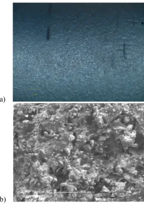
The inferences of the ICFT model may be better understood by viewing the specimen and fracture surfaces of TMF failed specimens. Figure 8 shows the specimen surface and fracture surface of an OP-TMF specimen failed with ±0.15% mechanical strain in the temperature range of 450-800oC. Because of the low strain amplitude, the model predicted low plastic and creep strains in this case, and life would be mostly limited by oxidation. As seen in Figure 8b, the fracture surface was totally oxidized. Figure 9 shows the specimen surface and fracture surface of
an OP-TMF specimen failed with ±0.25% mechanical strain in the temperature range of 450-800oC. In this case,
the high tensile OP stress induced multiple cracks on the specimen surface. The fracture surface had abundant grain boundary facets, indicating plasticity and IE were the dominant failure mechanism, even though isolated oxides could also be seen on the fracture surface. Figure 10 shows the specimen surface and fracture surface of an IP-TMF
specimen failed with ±0.3% mechanical strain in the temperature range of 300-800oC. The fracture surface
contained mostly distorted grain boundary facets and enlarged nodular voids. This observation corroborates with the
large creep deformation, as evaluated by the model. The fracture surface of 160-600oC constrained TMF exhibited a
mixed mode of plasticity-fatigue and IE, as shown in Figure 11, since the temperature range incorporated brittle failure observed at intermediate temperatures.
a) -400 -300 -200 -100 0 100 200 300 400 500 600
-4.00E-03 -3.00E-03 -2.00E-03 -1.00E-03 0.00E+00 1.00E-03 2.00E-03 3.00E-03 4.00E-03
St re ss (M Pa ) Strain (mm/mm) Model Exp. 1st cycle Exp. Mid-life
b) -0.006 -0.004 -0.002 0 0.002 0.004 0.006 0 100 200 300 400 500 600 700 800 900 1000 0 100 200 300 400 500 St ra in Te m pe ra tu re , K Time (sec) Temperature Creep Plasticity Creep+Plasticity Experiment
Figure 6. The hysteresis behaviour, a) and b) strain accumulation during constrained TMF with the constraint ratio
of 100% in the range of 160-600oC. 10 100 1000 10 100 1000 M od el P re di ct io n Experimental Life 450-800C-OP 300-800C OP 300-800C IP 160-600C Constrained
Figure 7. Comparison of the model predicted life with experiments for DCI.
b)
Figure 8: OP-TMF specimen failed with ±0.15% mechanical strain in the temperature range of 450-800oC: a) the
specimen surface; b) the fracture surface.
a)
b)
Figure 9. OP-TMF specimen failed with ±0.25% mechanical strain in the temperature range of 450-800oC : a) the
a)
b)
Figure 10: IP-TMF failed with ±0.3% mechanical strain in the temperature range of 300-800oC : a) the specimen
surface; b) the fracture surface.
Figure 11. Fracture surface of TMF specimen with a constraint ratio of 100% in the temperature range of 160-600oC.
CONCLUSIONS
In this study, the integrated creep-fatigue theory (ICFT) has been shown to provide mechanism-based descriptions of the LCF and TMF phenomena including cyclic stress-strain relationship, hysteresis loop, and life of DCI at various strain rates from 0.0002/s to 0.02/s, with different loading wave forms and with or without hold, in
the temperature range of RT to 800oC. In particular, four major damage mechanisms are considered in the model: i)
plasticity-induced mechanical fatigue, ii) intergranular embrittlement, iii) creep, and iv) oxidation. The model provides quantitative delineation of these mechanisms in the overall damage accumulation, and hence it provides physics-based life prediction with respect to the underlying deformation and damage mechanism. On the contrary, the linear damage summation rule does not offer a self-consistent explanation of the DCI-LCF/TMF phenomena.
For DCI-LCF, the model predicates that the room temperature LCF life is primarily driven by cyclic plasticity;
but at 400oC, even though the deformation still occurs by plasticity, intergranular embrittlement can dominate the
fracture process, which leads to a significant life reduction. As the temperature is increased above 600oC, rate-dependent stress-strain behaviour can be significantly manifested, such that the cyclic stress is relaxed to allow the
specimen to tolerate a longer crack to final fracture. Meanwhile, oxidation became the dominant damage
mechanism. The model predicts a crossover-behaviour between room temperature and high-temperature (>600oC)
strain-life relationships, as observed in the experiments.
For TMF, the ICFT model describes the asymmetrical hysteresis behaviour with delineation of plasticity and creep contributions. It also satisfactorily predicts the TMF life for various phasing TMF cycles with different waveforms, with or without hold, all based on the aforementioned mechanisms identified from the LCF tests. The ICFT description is in good agreement with the experimental observations.
In conclusion, the ICFT model provides a comprehensive description of the cyclic stress-strain behaviour, the failure mode and life of DCI under LCF conditions involving a plethora of damage mechanisms. Most importantly in the physical sense, it delineates the many faceted roles of plasticity and creep in both stress-strain behaviour and damage accumulation processes that other existing models and damage rules do not offer. By the generality of its underlying principles, the ICFT has a wide applicability for metallic alloys and composites. Work is continuing in the authors’ laboratory on applying the ICFT model to nickel and cobalt base superalloys.
ACKNOWLEDGMENTS
The experiments from which the data were taken for validation of the model were conducted as a contract effort with Wescast Industries Inc. The authors also would like to acknowledge Ryan MacNeil, Weijie Chen and Dave Chow of National Research Council Canada, who contributed in the testing and metallurgical work.
REFERENCES
1. Frost, H.J., Ashby, M.F., 1982, Deformation Mechanism Maps, Pergamon Press.
2. Wu, X.J., Koul, A.K., and Krausz, A.S., 1993, “A Transgranular Fatigue Crack Growth Model Based on Restricted Slip Reversibility,” Metall. Trans. A, Vol. 24A, 1373-1380.
3. Wu, X.J., Koul, A.K., 1995, “Grain Boundary Sliding in the Presence of Grain Boundary Precipitates during Transient Creep,” Metall. Trans. A, Vol. 26, 905-913.
4. Wu, X.J. Yandt, S., Zhang, Z., “A Framework of Integrated Creep-Fatigue Modeling,” Proceedings of the ASME Turbo Expo 2009, GT2009-59087, June 8-12, 2009, Orlando, Florida, USA.
5. Wu, X.J., 2009, “A Model of Nonlinear Fatigue- Creep (Dwell) Interactions,” ASME J. Gas Turbine Powers, Vol. 131, 032101.
6. Wu, X.J. Quan, G., MacNeil, R., Zhang Z., Sloss, C., 2014, “Failure Mechanisms and Damage Model of Ductile Cast Iron under Low-Cycle Fatigue Conditions,” Metall. and Mater. Trans. A, Vol. 45A, pp.5088-5097.
7. Slavik, D., Sehitoglu, H., 1987, “Thermal Stress, Materials Deformation, and Thermo-mechanical Fatigue,” ASME, PVP 123, pp. 65-82.
8. Lemaitre, J., Chaboche, J.L., 1999, Mécanique des Matériaux Solides, Dunod, Bordas, Paris. 9. Kachanov, L.M. , 1958, “On Creep Rupture Time,” Proc. Acad. Sci. USSR, 8, p 26–31.
10. Robotnov, Y.N., 1969, Creep Problems in Structural Members (English translation), F.A. Leckie, Ed., North Holland, Boston Spa.
11. Sehitoglu, H. 1992, “Thermo-Mechanical Fatigue Life Prediction Methods,” Advances in Fatigue Lifetime Predictive Techniques, ASTM STP 1122, pp. 47–76.
12. Wu, X.J., Koul, A.K., 1996, “Modelling Creep in Complex Engineering Alloys,” in Creep and Stress Relaxation in Miniature Structures and Components, TMS, Warrendale, PA, p 3–19.
13. Wu, X.J., Williams, S. and Gong, D.G., 2012, “A True-Stress Creep Model Based on Deformation Mechanisms for Polycrystalline Materials,” Journal of Materials Engineering and Performance, Vol. 21, pp. 2255-2262.