https://doi.org/10.4224/23000737
READ THESE TERMS AND CONDITIONS CAREFULLY BEFORE USING THIS WEBSITE. https://nrc-publications.canada.ca/eng/copyright
Vous avez des questions? Nous pouvons vous aider. Pour communiquer directement avec un auteur, consultez la première page de la revue dans laquelle son article a été publié afin de trouver ses coordonnées. Si vous n’arrivez pas à les repérer, communiquez avec nous à [email protected].
Questions? Contact the NRC Publications Archive team at
[email protected]. If you wish to email the authors directly, please see the first page of the publication for their contact information.
Archives des publications du CNRC
For the publisher’s version, please access the DOI link below./ Pour consulter la version de l’éditeur, utilisez le lien DOI ci-dessous.
Access and use of this website and the material on it are subject to the Terms and Conditions set forth at
Heavy duty vehicle rear-view camera systems: phase II
Mcwha, T.
https://publications-cnrc.canada.ca/fra/droits
L’accès à ce site Web et l’utilisation de son contenu sont assujettis aux conditions présentées dans le site
LISEZ CES CONDITIONS ATTENTIVEMENT AVANT D’UTILISER CE SITE WEB.
NRC Publications Record / Notice d'Archives des publications de CNRC:
https://nrc-publications.canada.ca/eng/view/object/?id=71253a26-b674-465d-9912-0a570d09616c https://publications-cnrc.canada.ca/fra/voir/objet/?id=71253a26-b674-465d-9912-0a570d09616c
National Research Council Canada Conseil National de Recherches Canada Automotive and Surface Transportation Automobile et transports de surface
Heavy-Duty Vehicle Rear-View Camera
Systems – Phase II
Prepared for: Marc Belzile
ecoTechnology for Vehicles Transport Canada 330 Sparks St. Ottawa, Ontario Canada, K1A 0N5 Prepared by: T. McWha, P.Eng Project A1-001055 ST-GV-TR-0015 March 31, 2014 UNLIMITED UNCLASSIFIED
Copyright 2014. This document contains confidential information that is proprietary to NRC Automotive and Surface Transportation. No part of its contents may be used, copied, disclosed or conveyed to any party in any manner, in whole or in part, whatsoever without prior written permission from NRC Automotive and Surface Transportation.
ST-GV-TR-0015 i
March 31, 2014 National Research Council of Canada
Automotive and Surface Transportation
Revision B
HEAVY DUTY VEHICLE REAR-VIEW CAMERA SYSTEMS – PHASE II
Prepared for: Marc Belzile
ecoTechnology for Vehicles Transport Canada
330 Sparks St. Ottawa, Ontario Canada, K1A 0N5
National Research Council of Canada Surface Transportation 2320 Lester Rd. Ottawa, Ontario Canada, K1V 1S2 Technical Report ST-GV-TR-0015
Copyright 2014. This document contains confidential information that is proprietary to NRC Automotive and Surface Transportation.
No part of its contents may be used, copied, disclosed or conveyed to any party in any manner, in whole or in part, whatsoever
March 31, 2014 National Research Council of Canada Automotive and Surface Transportation
Revision B
ST-GV-TR-0015 iii
March 31, 2014 National Research Council of Canada
Automotive and Surface Transportation
Revision B
C
HANGE
C
ONTROL
Revision Date Description Author
A March 4, 2014 Initial release T. McWha
March 31, 2014 National Research Council of Canada Automotive and Surface Transportation
Revision B
ST-GV-TR-0015 v
March 31, 2014 National Research Council of Canada
Automotive and Surface Transportation
Revision B
A
BSTRACT
Transport Canada, through its ecoTECHNOLOGY for Vehicles program, retained the services of the National Research Council Canada, as represented by the portfolio for Automotive and Surface Transportation to undertake a test program to examine the operational and human factors considerations concerning the use of a prototype camera-based indirect vision system on a heavy duty vehicle. The primary objective of the camera-based indirect vision system test program was to conduct a preliminary evaluation of the use of cameras in replacement of a mirror-based indirect vision system on a heavy duty vehicle by performing comparative testing in simulated driving scenarios on a closed course test track using commercial drivers as test subjects. A total of four test subjects were asked to perform six tests, although not all of the test subjects completed all of the available tests.
March 31, 2014 National Research Council of Canada Automotive and Surface Transportation
Revision B
ST-GV-TR-0015 vii
March 31, 2014 National Research Council of Canada
Automotive and Surface Transportation
Revision B
E
XECUTIVE
S
UMMARY
Transport Canada, through its ecoTECHNOLOGY for Vehicles program, retained the services of the National Research Council Canada (NRC), as represented by the portfolio for Automotive and Surface Transportation (AST) to undertake a test program to examine the operational and human factors considerations concerning the use of a prototype camera-based indirect vision system on a heavy duty vehicle. Indirect vision systems are used by drivers to identify objects that do not fall directly within their line of sight. This can be accomplished through the use of a conventional mirror-based indirect vision system or by a camera-based indirect vision system. The test program to date has been divided into two phases. In the first phase of the program, NRC-AST evaluated the design factors surrounding the use of camera-based indirect vision systems, quantified the possible fuel savings associated with the use of such a system, and designed and installed a prototype camera-based indirect vision system on a commercial highway tractor. The primary objective of the second phase of the camera-based indirect vision system test program was to conduct a preliminary evaluation of the use of cameras in
replacement of a mirror-based indirect vision system on a heavy duty vehicle by performing comparative testing in simulated driving scenarios on a closed course test track using commercial drivers as test subjects.
Two vehicles were used to test the camera-based indirect vision system: the subject vehicle and the target vehicle. The subject vehicle was a Volvo VN780 highway tractor with a 53 foot dry van semi-trailer. The camera-based indirect vision system installed in the subject vehicle consisted of four Panasonic WV-CP624 cameras, two cameras mounted on either side of the subject vehicle on the front fender. Four monitors were mounted on the A-pillars of the subject vehicle, one for each camera. The vehicle was prepared such that the camera-based indirect vision system and the mirror-based indirect vision system could be interchanged, allowing for comparison testing of the two systems. The target vehicle was a 2013 black Ford Focus Model SE.
A total of four test subjects were asked to perform six tests, although not all of the test subjects completed all of the available tests. The six tests were an object identification test, a blind spot comparison test, a coupling and uncoupling test, a quasi-static lane change test, a dynamic lane change test and an evasive manoeuvres test.
The purpose of the object identification test was to compare the test subjects’ ability to locate and identify targets while using both the conventional mirror-based indirect vision systems as well as the camera-based indirect vision system. The test was completed in both daytime and nighttime lighting conditions. Four test objects were used for the object identification test: a person, a road cone, a stop sign and a bicycle. Each object was presented four times for a total of sixteen tests per test condition. All four of the test subjects performed the test.
The results of the object identification test suggest that there is an increased ability to locate an object using the camera-based indirect vision system over the mirror-based indirect vision system. However, there is an increased ability to identify an object using a mirror-based indirect vision system over a camera-based indirect vision system.
The purpose of the blind spot comparison test was to compare the ability of the test subject to detect the presence of a target vehicle located alongside the subject vehicle. The test was performed both with the conventional mirror-based indirect vision system as well as the camera-based indirect vision system during daytime lighting conditions. All four of the test subjects performed the test.
March 31, 2014 National Research Council of Canada Automotive and Surface Transportation
Revision B
The blind spot comparison tests did not reveal any significant differences between the size or location of the blind spots associated with either indirect vision system. Although the final position of the target vehicle varied with the test subject as well as between systems, the size of the variation was not large enough to make a vehicle not visible to the test subject while using either system.
The purpose of the coupling and uncoupling test was to determine whether or not the test subject could adequately perform a series of simple coupling manoeuvers which they may be expected to perform during typical transport operations. The test was performed both with the conventional mirror-based indirect vision system as well as the camera-based indirect vision system during daytime and nighttime driving conditions. Two of the four test subjects performed the test.
The results of the coupling and uncoupling test revealed that the test subjects were capable of positioning the subject vehicle’s trailer within the cones of the simulated loading dock with the camera-based indirect vision system and with the mirror-based indirect vision system. In general, both test subjects took more time performing the required manoeuvres during daytime conditions with the camera-based indirect vision system compared to the mirror-based indirect vision system, but showed significant improvement during nighttime tests when using the camera-based indirect vision system compared to the mirror-based indirect vision system. The purpose of the quasi-static lane change test was to quantify the ability of the driver to perceive the location of the zero clearance distance position of the target vehicle. The zero clearance distance position of the target vehicle occurs when the front bumper of the target vehicle contacts the imaginary plane extending laterally from the end of the subject vehicle trailer. The test was performed both with the conventional mirror-based indirect vision system as well as the camera-based indirect vision system during daytime and nighttime lighting conditions. Three of the four test subjects performed the test.
The results of the quasi-static lane change test may be summarized by two findings. Firstly, the test subjects were not able to accurately locate the zero clearance distance position with either the mirror-based or camera-based indirect vision systems. Secondly, there were significant differences in the perceived location of the zero clearance distance position between the mirror-based and camera-mirror-based indirect vision systems. The noted differences in the perceived location of the zero clearance distance position between indirect vision systems were not consistent with the system under test, but varied between tests and test subjects. These differences in the perceived location of the zero clearance distance position revealed that the careful calibration of the camera fields of view to provide a similar sense of depth as is available with the use of a mirror-based indirect vision system was ineffective.
The purpose of the dynamic lane change test was to compare the ability of the driver to perform lane change maneuvers with each of the tested indirect vision systems. The test was
performed both with the conventional mirror-based indirect vision system as well as the camera-based indirect vision system during daytime and nighttime lighting conditions. Two test speeds were used for the target vehicle: 40 km/h and 74 km/h. The subject vehicle’s passing speeds were 50 km/h and 80 km/h. Two of the four test subjects performed the test.
The results of the dynamic lane change test revealed that the test subjects allowed for much more clearance distance between the subject vehicle and the target vehicle while using the camera-based indirect vision system than they did while using the mirror-based indirect vision system. The larger allowance of clearance distance while changing lanes with the camera-based indirect vision system was likely a result of the test subject not knowing the location of the end of the subject vehicle trailer.
ST-GV-TR-0015 ix
March 31, 2014 National Research Council of Canada
Automotive and Surface Transportation
Revision B
The purpose of the evasive maneuvers test was to assess the ability of the test subject to determine whether a lane change could be successfully completed in the event of a sudden and unforeseen road obstruction. The test was performed both with the conventional mirror-based indirect vision system as well as the camera-based indirect vision system during daytime and nighttime lighting conditions. Two of the four test subjects performed the test.
The results of the evasive manoeuvres test revealed that the test subjects had difficulty in determining the location of the rear of the subject vehicle’s trailer, similar to the results of the quasi-static lane change and dynamic lane change tests. Determining the location of the rear of the subject vehicle’s trailer was made even more difficult at night as a result of the camera bloom emanating from the target vehicle’s headlights. The test subjects were much more hesitant in their lane changing manoeuvres during nighttime operations with the camera-based indirect vision system compared to similar lane change manoeuvres with the mirror-based indirect vision system as a result of the blooming effect of the digital cameras. However, at no point during testing did the test subjects attempt to perform a lane change manoeuvre which would have caused a collision.
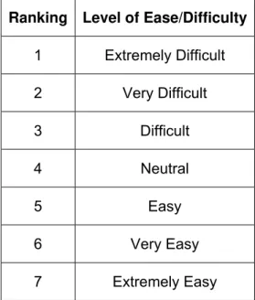
After each test, the test subjects were provided with questionnaires as a way to gather both qualitative and quantitative user data. The test subjects were asked to rate the level of ease or difficulty they associated with each test manoeuvre for both the camera-based indirect vision system and the mirror-based indirect vision system. The test subjects were also asked to provide comments on what they liked and did not like about the camera-based indirect vision system. In addition, they were encouraged to provide feedback on ways to improve the camera-based indirect vision system.
In general, the test subjects rated the camera-based indirect vision system as more difficult to use than the mirror-based indirect vision system. In terms of the comments received from the test subjects, the most frequent concern was that of blooming in the monitors as a result of viewing bright lights during nighttime operations. Test subjects were also concerned about the resolution of the system, difficulties in proper depth perception, and the lack of control over the cameras fields of view and monitor brightness. However, test subjects did enjoy the greater forward field of view associated with the use of a camera-based indirect vision system as result of the removal of the mirrors, as well as the smaller scan area associated with such a system. The preliminary comparison of the camera-based indirect vision system with a conventional mirror-based indirect vision system revealed that the camera-based indirect vision system provided potential advantages in locating and identifying objects during nighttime operations. This was shown in the object identification test as well as the coupling and uncoupling test. However, it was during nighttime operations when the camera-based indirect vision system was at its most vulnerable due to image blooming as a result of bright objects within the camera fields of view. This was also the most frequent concern about the system listed by the test subjects on the questionnaires. It will be important to resolve the issue of image blooming in any subsequent revision of the camera-based indirect vision system.
The quasi-static lane change test, the dynamic lane change test and the evasive manoeuvre test all revealed that the test subject’s inability to locate the end of their trailer resulted in hesitation to perform lane changes which could be deemed as safe to perform. However, the quasi-static lane change test revealed that the test subjects were not any better in locating the actual position of their trailer with a mirror-based indirect vision system. The hesitation in performing lane change manoeuvres, especially during daytime conditions, could be the result of unfamiliarity with the use of a camera-based indirect vision system. During nighttime
conditions, it is likely a combination of this unfamiliarity and the aforementioned issue of image blooming.
March 31, 2014 National Research Council of Canada Automotive and Surface Transportation
Revision B
It was found that the careful calibration of the camera fields of view to provide a similar sense of depth as is available with the use of a mirror-based indirect vision system was ineffective. This finding allows for the placement of the cameras in locations other than the front fender of the equipped vehicle. This will allow for cameras to be mounted in locations which are less susceptible to road debris and soiling. This will also allow for placement of the cameras in the location which results in the greatest reduction in aerodynamic drag, the potential for
aerodynamic drag reduction and the resultant fuel savings being the main driver for the adoption of camera-based indirect vision systems. The attempt at simulating depth perception through careful selection of camera fields of view was also an important consideration in choosing the size of the system monitors in the first phase of this program. The finding that this methodology is ineffective allows for greater flexibility in the sizing of the monitors. Although there is an upper practical limit on the size of the monitors, the larger the monitor, the more visual information may be provided to the vehicle operator.
ST-GV-TR-0015 xi
March 31, 2014 National Research Council of Canada
Automotive and Surface Transportation
Revision B
T
ABLE OF
C
ONTENTS
1 Introduction ... 1 1.1 Purpose ... 1 1.2 Background ... 1 1.3 Objectives... 1 1.4 Limitations ... 1 2 Apparatus ... 2 2.1 Test Vehicles ... 2 2.1.1 Subject Vehicle ... 2 2.1.2 Target Vehicle ... 5 2.2 Instrumentation... 5 2.3 Data Acquisition ... 6 3 Test Subjects ... 7 4 Test Procedures ... 9 4.1 Object Identification ... 9
4.2 Blind Spot Comparison ... 13
4.3 Coupling and Uncoupling ... 15
4.4 Quasi-Static Lane Change ... 21
4.5 Dynamic Lane Change ... 24
4.6 Evasive Manoeuvre ... 27 4.7 Questionnaires ... 30 5 Results ... 31 5.1 Object Identification ... 31 5.1.1 Driver 1 ... 31 5.1.2 Driver 2 ... 36 5.1.3 Driver 3 ... 36 5.1.4 Driver 4 ... 36 5.1.5 Summary of Results ... 49 5.1.6 Results of Questionnaire ... 50
5.2 Blind Spot Comparison ... 52
5.2.1 Driver 1 ... 52
5.2.2 Driver 2 ... 53
March 31, 2014 National Research Council of Canada Automotive and Surface Transportation
Revision B
5.2.4 Driver 4 ... 55
5.2.5 Results of Questionnaire ... 56
5.3 Coupling and Uncoupling ... 58
5.3.1 Driver 2 ... 59
5.3.2 Driver 3 ... 61
5.3.3 Results of Questionnaire ... 62
5.4 Quasi-Static Lane Change ... 63
5.4.1 Driver 1 ... 64
5.4.2 Driver 2 ... 70
5.4.3 Driver 3 ... 76
5.4.4 Results of Questionnaire ... 82
5.5 Dynamic Lane Change ... 83
5.5.1 Driver 2 ... 84 5.5.2 Driver 3 ... 87 5.5.3 Results of Questionnaire ... 90 5.6 Evasive Manoeuvre ... 91 5.6.1 Driver 2 ... 92 5.6.2 Driver 3 ... 94 5.6.3 Results of Questionnaire ... 96 5.7 Additional Findings ... 97
5.7.1 Moving Cameras Outboard ... 97
5.7.2 Blooming ... 98
6 Analysis ... 99
6.1 Object Identification ... 99
6.2 Blind Spot Comparison ... 105
6.3 Coupling and Uncoupling ... 109
6.4 Quasi-Static Lane Change ... 113
6.4.1 Driver 1 ... 113
6.4.2 Driver 2 ... 119
6.4.3 Driver 3 ... 125
6.5 Dynamic Lane Change ... 133
6.6 Evasive Manoeuvre ... 136
6.7 Questionnaires ... 138
7 Conclusions ... 140
ST-GV-TR-0015 xiii
March 31, 2014 National Research Council of Canada
Automotive and Surface Transportation
Revision B
7.2 Blind Spot Comparison ... 140
7.3 Coupling and Uncoupling ... 140
7.4 Quasi-Static Lane Change ... 141
7.5 Dynamic Lane Change ... 142
7.6 Evasive Manoeuvre ... 142
7.7 Questionnaires ... 142
7.8 Additional Findings ... 143
8 Discussion ... 144
9 Acronyms and Abbreviations ... 146
10 References ... 147
March 31, 2014 National Research Council of Canada Automotive and Surface Transportation
Revision B
ST-GV-TR-0015 xv
March 31, 2014 National Research Council of Canada
Automotive and Surface Transportation
Revision B
L
IST OF
F
IGURES
Figure 1: Subject vehicle ... 2
Figure 2: Driver side camera housing ... 3
Figure 3: Passenger side camera housing ... 3
Figure 4: System monitors mounted on left A-pillar ... 4
Figure 5: System monitors mounted on right A-pillar ... 4
Figure 6: Target vehicle ... 5
Figure 7: Objects used for object identification test (left to right: stop sign, bike, cone, person) 10 Figure 8: Object identification test object locations ... 10
Figure 9: Mirror obstruction device closed (left) and open (right) ... 13
Figure 10: Starting position of target vehicle for blind spot comparison test (driver side test) .... 14
Figure 11: Final position of target vehicle for blind spot comparison test (driver side test) ... 14
Figure 12: Postioning of cones for simulated loading dock for coupling and uncoupling test ... 16
Figure 13: Simulated loading dock for coupling and uncoupling test ... 16
Figure 14: Coupling and uncoupling manoeuvre (driver side approach) ... 17
Figure 15: Starting position for coupling and uncoupling test (driver side approach) ... 18
Figure 16: Final position for coupling and uncoupling test (driver side approach) ... 18
Figure 17: Coupling and uncoupling manoeuvre (passenger side approach) ... 19
Figure 18: Starting position for coupling and uncoupling test (passenger side approach) ... 20
Figure 19: Final position for coupling and uncoupling test (passenger side approach) ... 20
Figure 20: Laser reflection panel mounted to target vehicle ... 22
Figure 21: Laser reflection panel structure ... 22
Figure 22: Rearmost (top), flush (middle) and foremost (bottom) target vehicle positions ... 23
Figure 23: Laser distance meter affixed to the side of the target vehicle ... 25
Figure 24: Laser reflection panels affixed to the rear of the subject vehicle ... 25
Figure 25: Laser reflection panels affixed to the rear of the subject vehicle ... 26
Figure 26: Evasive manoeuvre target locations ... 28
Figure 27: Evasive manoeuvre test positions one (top), three (middle) and five (bottom) ... 29
Figure 28: Driver 2 contacting cones during coupling and uncoupling test with mirrors ... 59
Figure 29: Driver 1 quasi-static lane change results for mirror test with target vehicle on driver side (day) ... 66
Figure 30: Driver 1 quasi-static lane change results for camera test with target vehicle on driver side (day) ... 66
March 31, 2014 National Research Council of Canada Automotive and Surface Transportation
Revision B
Figure 31: Driver 1 quasi-static lane change results for mirror test with target vehicle on
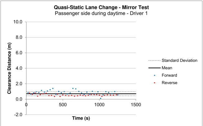
passenger side (day) ... 67 Figure 32: Driver 1 quasi-static lane change results for camera test with target vehicle on
passenger side (day) ... 67 Figure 33: Driver 1 quasi-static lane change results for mirror test with target vehicle on driver
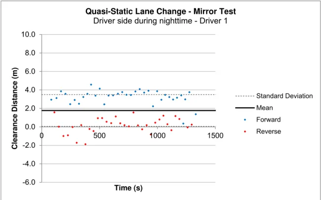
side (night) ... 68 Figure 34: Driver 1 quasi-static lane change results for camera test with target vehicle on driver
side (night) ... 68 Figure 35: Driver 1 quasi-static lane change results for mirror test with target vehicle on
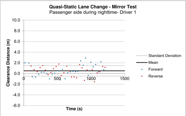
passenger side (night) ... 69 Figure 36: Driver 1 quasi-static lane change results for camera test with target vehicle on
passenger side (night) ... 69 Figure 37: Driver 2 quasi-static lane change results for mirror test with target vehicle on driver
side (day) ... 72 Figure 38: Driver 2 quasi-static lane change results for camera test with target vehicle on driver
side (day) ... 72 Figure 39: Driver 2 quasi-static lane change results for mirror test with target vehicle on
passenger side (day) ... 73 Figure 40: Driver 2 quasi-static lane change results for camera test with target vehicle on
passenger side (day) ... 73 Figure 41: Driver 2 quasi-static lane change results for mirror test with target vehicle on driver
side (night) ... 74 Figure 42: Driver 2 quasi-static lane change results for camera test with target vehicle on driver
side (night) ... 74 Figure 43: Driver 2 quasi-static lane change results for mirror test with target vehicle on
passenger side (night) ... 75 Figure 44: Driver 2 quasi-static lane change results for camera test with target vehicle on
passenger side (night) ... 75 Figure 45: Driver 3 quasi-static lane change results for mirror test with target vehicle on driver
side (day) ... 78 Figure 46: Driver 3 quasi-static lane change results for camera test with target vehicle on driver
side (day) ... 78 Figure 47: Driver 3 quasi-static lane change results for mirror test with target vehicle on
passenger side (day) ... 79 Figure 48: Driver 3 quasi-static lane change results for camera test with target vehicle on
passenger side (day) ... 79 Figure 49: Driver 3 quasi-static lane change results for mirror test with target vehicle on driver
side (night) ... 80 Figure 50: Driver 3 quasi-static lane change results for camera test with target vehicle on driver
side (night) ... 80 Figure 51: Driver 3 quasi-static lane change results for mirror test with target vehicle on
ST-GV-TR-0015 xvii
March 31, 2014 National Research Council of Canada
Automotive and Surface Transportation
Revision B
Figure 52: Driver 3 quasi-static lane change results for camera test with target vehicle on
passenger side (night) ... 81
Figure 53: Driver side cameras moved away from subject vehicle surface ... 97
Figure 54: Blooming in monitors caused by target vehicle’s headlights ... 98
Figure 55: Proportion of correctly identified test objects for object identification test (Driver 1) 100 Figure 56: Proportion of correctly identified test objects for object identification test (Driver 2) 100 Figure 57: Proportion of correctly identified test objects for object identification test (Driver 3) 101 Figure 58: Proportion of correctly identified test objects for object identification test (Driver 4) 101 Figure 59: Time to locate test objects for object identification test (Driver 1) ... 102
Figure 60: Time to locate test objects for object identification test (Driver 2) ... 103
Figure 61: Time to locate test objects for object identification test (Driver 3) ... 103
Figure 62: Time to locate test objects for object identification test (Driver 4) ... 104
Figure 63: Position vectors for driver side blind spot comparison testing ... 105
Figure 64: Blind spot comparison results for Driver 1 ... 106
Figure 65: Blind spot comparison results for Driver 2 ... 106
Figure 66: Blind spot comparison results for Driver 3 ... 107
Figure 67: Blind spot comparison results for Driver 4 ... 107
Figure 68: Blind spot comparison results for all drivers ... 108
Figure 69: Elapsed time for daytime coupling and uncoupling tests (Driver 2) ... 110
Figure 70: Elapsed time for nighttime coupling and uncoupling tests (Driver 2) ... 110
Figure 71: Elapsed time for daytime coupling and uncoupling tests (Driver 3) ... 112
Figure 72: Elapsed time for nighttime coupling and uncoupling tests (Driver 3) ... 112
Figure 73: Driver 1 quasi-static lane change results for mirror test with target vehicle on driver side moving in reverse direction (day) ... 118
Figure 74: Driver 1 quasi-static lane change results for camera test with target vehicle on driver side moving in reverse direction (day) ... 118
Figure 75: Driver 2 quasi-static lane change results for mirror test with target vehicle on driver side moving in reverse direction (day) ... 124
Figure 76: Driver 2 quasi-static lane change results for camera test with target vehicle on driver side moving in reverse direction (day) ... 124
Figure 77: Driver 3 quasi-static lane change results for mirror test with target vehicle on driver side moving in forward direction (day) ... 130
Figure 78: Driver 3 quasi-static lane change results for camera test with target vehicle on driver side moving in forward direction (day) ... 130
Figure 79: Driver 3 quasi-static lane change results for mirror test with target vehicle on driver side moving in reverse direction (night) ... 131
Figure 80: Driver 3 quasi-static lane change results for camera test with target vehicle on driver side moving in reverse direction (night) ... 131
March 31, 2014 National Research Council of Canada Automotive and Surface Transportation
Revision B
Figure 81: Driver 3 quasi-static lane change results for mirror test with target vehicle on
passenger side moving in reverse direction (night) ... 132 Figure 82: Driver 3 quasi-static lane change results for camera test with target vehicle on
passenger side moving in reverse direction (night) ... 132 Figure 83: Average clearance distance during daytime dynamic lane change tests (Driver 2) 133 Figure 84: Average clearance distance during nighttime dynamic lane change tests (Driver 2)
... 134 Figure 85: Average clearance distance during daytime dynamic lane change tests (Driver 3) 134 Figure 86: Average clearance distance during nighttime dynamic lane change tests (Driver 3)
... 135 Figure 87: Proportion of correct decisions for evasive manoeuvre test ... 137
ST-GV-TR-0015 xix
March 31, 2014 National Research Council of Canada
Automotive and Surface Transportation
Revision B
L
IST OF
T
ABLES
Table 1: List of instrumentation ... 5 Table 2: Test subject details ... 7 Table 3: Tests completed by test subjects ... 8 Table 4: Daytime object identification test ... 11 Table 5: Nighttime object identification test ... 12 Table 6: Target vehicle positions for evasive manoeuvre test ... 28 Table 7: Scale used to rate the indirect vision system under test ... 30 Table 8: List of test subjects for object identification test ... 31 Table 9: Driver 1 object identification test results for daytime with cameras ... 32 Table 10: Driver 1 object identification test results for daytime with mirrors ... 33 Table 11: Driver 1 object identification test results for nighttime with cameras... 34 Table 12: Driver 1 object identification test results for nighttime with mirrors ... 35 Table 13: Driver 2 object identification test results for daytime with cameras... 37 Table 14: Driver 2 object identification test results for daytime with mirrors ... 38 Table 15: Driver 2 object identification test results for nighttime with cameras... 39 Table 16: Driver 2 object identification test results for nighttime with mirrors ... 40 Table 17: Driver 3 object identification test results for daytime with cameras... 41 Table 18: Driver 3 object identification test results for daytime with mirrors ... 42 Table 19: Driver 3 object identification test results for nighttime with cameras... 43 Table 20: Driver 3 object identification test results for nighttime with mirrors ... 44 Table 21: Driver 4 object identification test results for daytime with cameras... 45 Table 22: Driver 4 object identification test results for daytime with mirrors ... 46 Table 23: Driver 4 object identification test results for nighttime with cameras... 47 Table 24: Driver 4 object identification test results for nighttime with mirrors ... 48 Table 25: Summary of results for object identification test ... 49 Table 26: Quantitative results of object identification questionnaire ... 50 Table 27: Qualitative results of object identification questionnaire ... 51 Table 28: List of test subjects for blind spot comparison test ... 52 Table 29: Results of blind spot comparison test with target vehicle on driver side (Driver 1) ... 52 Table 30: Results of blind spot comparison test with target vehicle on passenger side (Driver 1)
... 53 Table 31: Results of blind spot comparison test with target vehicle on driver side (Driver 2) ... 53
March 31, 2014 National Research Council of Canada Automotive and Surface Transportation
Revision B
Table 32: Results of blind spot comparison test with target vehicle on passenger side (Driver 2) ... 54 Table 33: Results of blind spot comparison test with target vehicle on driver side (Driver 3) ... 54 Table 34: Results of blind spot comparison test with target vehicle on passenger side (Driver 3)
... 55 Table 35: Results of blind spot comparison test with target vehicle on driver side (Driver 4) ... 55 Table 36: Results of blind spot comparison test with target vehicle on passenger side (Driver 4)
... 56 Table 37: Quantitative results of blind spot comparison test questionnaire ... 56 Table 38: Qualitative results of blind spot comparison test questionnaire ... 57 Table 39: List of test subjects for coupling and uncoupling test ... 58 Table 40: Results of coupling and uncoupling test for Driver 2 ... 60 Table 41: Results of coupling and uncoupling test for Driver 3 ... 61 Table 42: Quantitative results of coupling and uncoupling test questionnaire ... 62 Table 43: Qualitative results of coupling and uncoupling test questionnaire ... 62 Table 44: List of test subjects for quasi-static lane change test ... 63 Table 45: Driver 1 quasi-static lane change test results (day) ... 64 Table 46: Driver 1 quasi-static lane change test results (night) ... 65 Table 47: Driver 2 quasi-static lane change test results (day) ... 70 Table 48: Driver 2 quasi-static lane change test results (night) ... 71 Table 49: Driver 3 quasi-static lane change test results (day) ... 76 Table 50: Driver 3 quasi-static lane change test results (night) ... 77 Table 51: Quantitative results of quasi-static lane change questionnaire ... 82 Table 52: Qualitative results of quasi-static lane change questionnaire ... 82 Table 53: List of test subjects for dynamic lane change test ... 83 Table 54: Results of low speed dynamic lane change test with subject vehicle passing on the
left during the day (Driver 2) ... 84 Table 55: Results of low speed dynamic lane change test with subject vehicle passing on the
right during the day (Driver 2) ... 84 Table 56: Results of high speed dynamic lane change test with subject vehicle passing on the
left during the day (Driver 2) ... 85 Table 57: Results of high speed dynamic lane change test with subject vehicle passing on the
right during the day (Driver 2) ... 85 Table 58: Results of low speed dynamic lane change test with subject vehicle passing on the
left during the night (Driver 2) ... 85 Table 59: Results of low speed dynamic lane change test with subject vehicle passing on the
ST-GV-TR-0015 xxi
March 31, 2014 National Research Council of Canada
Automotive and Surface Transportation
Revision B
Table 60: Results of high speed dynamic lane change test with subject vehicle passing on the left during the night (Driver 2) ... 86 Table 61: Results of high speed dynamic lane change test with subject vehicle passing on the
right during the night (Driver 2) ... 86 Table 62: Results of low speed dynamic lane change test with subject vehicle passing on the
left during the day (Driver 3) ... 87 Table 63: Results of low speed dynamic lane change test with subject vehicle passing on the
right during the day (Driver 3) ... 87 Table 64: Results of high speed dynamic lane change test with subject vehicle passing on the
left during the day (Driver 3) ... 88 Table 65: Results of high speed dynamic lane change test with subject vehicle passing on the
right during the day (Driver 3) ... 88 Table 66: Results of low speed dynamic lane change test with subject vehicle passing on the
left during the night (Driver 3) ... 88 Table 67: Results of low speed dynamic lane change test with subject vehicle passing on the
right during the night (Driver 3) ... 89 Table 68: Results of high speed dynamic lane change test with subject vehicle passing on the
left during the night (Driver 3) ... 89 Table 69: Results of high speed dynamic lane change test with subject vehicle passing on the
right during the night (Driver 3) ... 89 Table 70: Quantitative results of dynamic lane change questionnaire ... 90 Table 71: List of test subjects for evasive manoeuvre test ... 91 Table 72: Results of evasive manoeuvre test during daytime (Driver 1) ... 92 Table 73: Results of evasive manoeuvre test during nighttime (Driver 1)... 93 Table 74: Results of evasive manoeuvre test during daytime (Driver 2) ... 94 Table 75: Results of evasive manoeuvre test during nighttime (Driver 2)... 95 Table 76: Quantitative results of evasive manoeuvre test questionnaire ... 96 Table 77: Qualitative results of evasive manoeuvre test questionnaire ... 96 Table 78: Results of test for statistical significance for object identification test results (p-values)
... 102 Table 79: Angular difference between position vectors for blind spot comparison test ... 108 Table 80: Average times for completion of coupling and uncoupling test (Driver 2) ... 111 Table 81: Average times for completion of coupling and uncoupling test (Driver 3) ... 111 Table 82: Driver 1 quasi-static lane change test results with target vehicle moving forward (day)
... 114 Table 83: Driver 1 quasi-static lane change test results with target vehicle moving forward
(night) ... 115 Table 84: Driver 1 quasi-static lane change test results with target vehicle moving in reverse
March 31, 2014 National Research Council of Canada Automotive and Surface Transportation
Revision B
Table 85: Driver 1 quasi-static lane change test results with target vehicle moving in reverse (night) ... 117 Table 86: Results of comparison of means test for quasi-static lane change test (Driver 1) .... 117 Table 87: Driver 2 quasi-static lane change test results with target vehicle moving forward (day)
... 120 Table 88: Driver 2 quasi-static lane change test results with target vehicle moving forward
(night) ... 121 Table 89: Driver 2 quasi-static lane change test results with target vehicle moving in reverse
(day) ... 122 Table 90: Driver 2 quasi-static lane change test results with target vehicle moving in reverse
(night) ... 123 Table 91: Results of comparison of means test for quasi-static lane change test (Driver 2) .... 123 Table 92: Driver 3 quasi-static lane change test results with target vehicle moving forward (day)
... 126 Table 93: Driver 3 quasi-static lane change test results with target vehicle moving forward
(night) ... 127 Table 94: Driver 3 quasi-static lane change test results with target vehicle moving in reverse
(day) ... 128 Table 95: Driver 3 quasi-static lane change test results with target vehicle moving in reverse
(night) ... 129 Table 96: Results of comparison of means test for quasi-static lane change test (Driver 2) .... 129 Table 97: Average elapsed decision times for evasive manoeuvres test ... 136 Table 98: Average test subject ratings of tested indirect vision systems ... 138
ST-GV-TR-0015 Page 1
March 31, 2014 National Research Council of Canada
Automotive and Surface Transportation
Revision B
1 I
NTRODUCTION
1.1 Purpose
Transport Canada (TC), through its ecoTECHNOLOGY for Vehicles (eTV) program, has retained the services of the National Research Council Canada (NRC), as represented by the portfolio for Automotive and Surface Transportation (AST), hereafter known as NRC-AST, to undertake a test program to examine the operational and human factors considerations
concerning the use of a prototype camera-based indirect vision system on a heavy duty vehicle.
1.2 Background
Indirect vision systems are used by drivers to identify objects that do not fall directly within their line of sight. This can be accomplished through the use of a conventional mirror-based indirect vision system or by a camera-based indirect vision system.
Conventional mirror-based indirect vision systems require large structures to be placed in the airflow passing the vehicle creating a significant amount of drag. The use of a camera-based indirect vision system requires smaller support structures, thereby reducing the overall drag coefficient of the vehicle on which they are mounted. The reduction in drag results in fuel savings and a corresponding reduction in emissions.
In Phase I of this study, NRC-AST evaluated the design factors surrounding the use of camera-based indirect vision systems, quantified the possible fuel savings associated with the use of such a system, and designed and installed a prototype camera-based indirect vision system on a Volvo VN780 highway tractor. [1]
1.3 Objectives
The primary objective of the camera-based indirect vision system test program is to conduct a preliminary evaluation of the use of cameras in replacement of a mirror-based indirect vision system on a heavy duty vehicle. In order to evaluate whether there are any significant changes to the operating environment in which the driver is situated as a result of removing the mirrors from the vehicle, the driver was placed in simulated driving scenarios on a closed course test track. The driver’s ability to efficiently operate the test vehicle with the use of the camera-based indirect vision system will be compared to the ability to efficiently operate the vehicle with the conventional mirror-based indirect vision system.
1.4 Limitations
There were several limitations concerning the testing of the camera-based indirect vision
system. Firstly, the sample size of test subjects used for the testing was small meaning that the results may not be representative of the entire population of commercial drivers. Secondly, there was no training given to the test subjects for them to adjust to the use of a camera-based indirect vision system. The test sequence was designed so that the tests became progressively more difficult, but no time was allotted for training of the test subjects. Thirdly, all tests were performed on a closed course in controlled conditions, removing the test subject from the environment in which they normally operated. Finally, there was no control over environmental factors. All tests occurred in conditions which were free of precipitation. Only once did
March 31, 2014 National Research Council of Canada Automotive and Surface Transportation
Revision B
2 A
PPARATUS
2.1 Test
Vehicles
Two vehicles were used to test the camera-based indirect vision system: the subject vehicle and the target vehicle.
2.1.1
Subject Vehicle
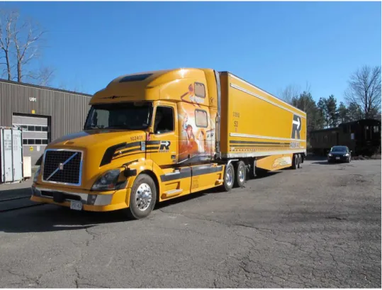
The subject vehicle was a Volvo VN780 highway tractor with a 53 foot dry van semi-trailer. The vehicle was prepared such that the camera-based indirect vision system and the mirror-based indirect vision system could be interchanged, allowing for comparison testing of the two systems. The subject vehicle with the camera-based indirect vision system may be seen in Figure 1.
Figure 1: Subject vehicle
The camera-based indirect vision system installed in the subject vehicle consisted of four Panasonic WV-CP624 cameras housed inside a temporary steel box to protect the cameras from any debris but still allow accessibility for the test team. The driver side and passenger side camera housings may be seen in Figure 2 and Figure 3, respectively.
Four monitors were mounted on the A-pillars of the subject vehicle, one for each camera. The monitors mounted on the left A-pillar (as shown in Figure 4) were a ToteVision LCD-562
mounted above a ToteVision LCD-642. The monitors mounted on the right A-pillar (as shown in Figure 5) were a ToteVision LCD-642 mounted above a ToteVision LCD-842HD.
Further details of the design and installation of the camera-based indirect vision system used in the testing described within this document may be found in the previously issued report [1].
ST-GV-TR-0015 Page 3
March 31, 2014 National Research Council of Canada
Automotive and Surface Transportation
Revision B
Figure 2: Driver side camera housing
March 31, 2014 National Research Council of Canada Automotive and Surface Transportation
Revision B
Figure 4: System monitors mounted on left A-pillar
ST-GV-TR-0015 Page 5
March 31, 2014 National Research Council of Canada
Automotive and Surface Transportation
Revision B
2.1.2
Target Vehicle
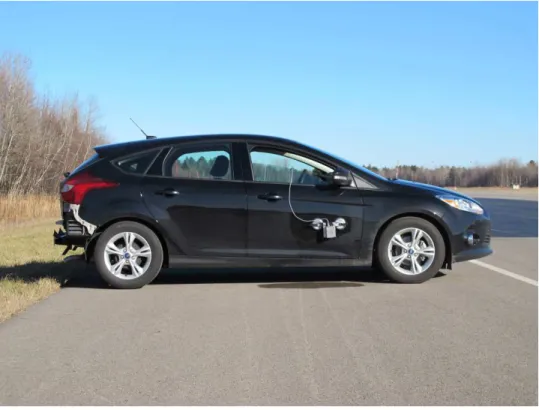
Four of the six tests which formed the test program required the use of a target vehicle. The target vehicle was a 2013 black Ford Focus Model SE. The target vehicle may be seen in Figure 6.
Figure 6: Target vehicle
2.2 Instrumentation
Table 1 provides details on the instrumentation installed during testing.
Table 1: List of instrumentation
Sensor Location Range Accuracy
Linear transducer Subject vehicle steering wheel (for
steering input measurement) 0-750 mm ±2 mm Laser distance meter Various locations depending upon
test 0.2-15 m <5 mm
Global positioning Target vehicle ∞ ±3 m Global positioning Subject vehicle ∞ ±3 m
March 31, 2014 National Research Council of Canada Automotive and Surface Transportation
Revision B
2.3 Data
Acquisition
Raw data were sampled at 100 Hz and filtered with a low pass Butterworth filter by an IMC data acquisition system. Data from each run were captured into memory and then stored onto the local hard drive. All recorded data were transferred to NRC-AST’s network after the testing was completed.
ST-GV-TR-0015 Page 7
March 31, 2014 National Research Council of Canada
Automotive and Surface Transportation
Revision B
3 T
EST
S
UBJECTS
A small sample of test subjects was used to evaluate the camera-based indirect vision system. All of the test subjects were male. Table 2 provides additional pertinent information describing the test subjects. Table 3 provides details of which test subjects completed which tests.
Table 2: Test subject details
Test Subject Age
Years of Commercial Driving Experience Vision Corrective Lenses Driver 1 62 35 20/20 Bifocals Driver 2 34 8 20/20 None Driver 3 36 7 20/25 None Driver 4 65 33 20/30 Bifocals
March 31, 2014 National Research Council of Canada Automotive and Surface Transportation
Revision B
Table 3: Tests completed by test subjects
Test Subject Completed Tests
Driver 1
Object Identification Blind Spot Comparison Coupling and Uncoupling Quasi-Static Lane Change
Driver 2
Object Identification Blind Spot Comparison Coupling and Uncoupling Quasi-Static Lane Change Dynamic Lane Change Evasive Manoeuvre
Driver 3
Object Identification Blind Spot Comparison Coupling and Uncoupling Quasi-Static Lane Change Dynamic Lane Change Evasive Manoeuvre
Driver 4 Object Identification Blind Spot Comparison
ST-GV-TR-0015 Page 9
March 31, 2014 National Research Council of Canada
Automotive and Surface Transportation
Revision B
4 T
EST
P
ROCEDURES
4.1 Object
Identification
The object identification test was performed on the premises of NRC-AST. The purpose of the object identification test was to compare the test subjects’ ability to locate and identify targets while using both the conventional mirror-based indirect vision systems as well as the camera-based indirect vision system. The test was completed in both daytime and nighttime lighting conditions. Although weather was not a controlled factor, all tests took place in precipitation free conditions.
Four test objects were used for the object identification test: a person, a road cone, a stop sign and a bicycle. The four test objects used during testing may be seen in Figure 7. The test locations in which the test objects were placed may be seen in Figure 8. Prior to the testing, four test locations were randomly selected for each of the four test objects. Sixteen locations were tested in total. Each driver was subjected to the same set of test object locations and order of object presentation. The test locations and order of presentation for daytime testing may be found in Table 4. The test locations and order of presentation for nighttime testing may be found in Table 5.
The subject vehicle was positioned in a rear lot of NRC-AST with the test subject in the driver’s seat. The test subject was asked to adjust the indirect vision system under test as they would under normal operating conditions. A grid was measured around the subject vehicle as shown in Figure 8 to locate the test objects.
To ensure the test subject could not see where the test object was being placed, the indirect vision system under test was obstructed. For the mirror-based indirect vision system, this was accomplished through the use of a spring loaded obstruction operated by a solenoid release mechanism, as shown in Figure 9. For the camera-based system, the video feed delivered to the monitors was interrupted via a toggle switch.
Once the test object was in position, the indirect-vision system was unobstructed and the time for the test subject to identify the test object was recorded using the data acquisition system. Upon completion of the object identification test, the test subject was provided with brief questionnaires to collect additional data. The object identification test questionnaires may be found in Appendix A and Appendix B.
March 31, 2014 National Research Council of Canada Automotive and Surface Transportation
Revision B
Figure 7: Objects used for object identification test (left to right: stop sign, bike, cone, person)
Figure 8: Object identification test object locations
2 1 3 4 5 6 8 7 9 10 11 12 14 13 15 16 17 18 20 19 21 22 23 24 26 25 27 28 29 30 32 31 33 34 35 36 1.88 m 5.00 m
ST-GV-TR-0015 Page 11
March 31, 2014 National Research Council of Canada
Automotive and Surface Transportation
Revision B
Table 4: Daytime object identification test
Test
Camera Test Locations Mirror Test Locations
Item Location Item Location
1 Cone 5 Cone 19
2 Bike 35 Stop sign 30
3 Cone 36 Bike 25
4 Bike 25 Cone 5
5 Cone 13 Bike 35
6 Person 15 Stop sign 11
7 Stop sign 9 Person 24
8 Stop sign 21 Bike 13
9 Cone 19 Person 13
10 Stop sign 30 Person 14
11 Bike 13 Bike 29
12 Stop sign 11 Cone 13
13 Person 14 Person 15
14 Person 13 Cone 36
15 Bike 29 Stop sign 9
March 31, 2014 National Research Council of Canada Automotive and Surface Transportation
Revision B
Table 5: Nighttime object identification test
Test
Camera Test Locations Mirror Test Locations
Item Location Item Location
1 Stop sign 11 Cone 36
2 Bike 25 Bike 35
3 Cone 36 Stop sign 21
4 Person 24 Person 15
5 Stop sign 21 Stop sign 9
6 Person 13 Cone 13
7 Bike 29 Bike 13
8 Person 15 Bike 25
9 Person 14 Stop sign 11
10 Stop sign 9 Bike 29
11 Cone 5 Person 24
12 Cone 13 Cone 5
13 Bike 13 Person 13
14 Stop sign 30 Person 14
15 Cone 19 Stop sign 30
ST-GV-TR-0015 Page 13
March 31, 2014 National Research Council of Canada
Automotive and Surface Transportation
Revision B
Figure 9: Mirror obstruction device closed (left) and open (right)
4.2 Blind
Spot
Comparison
The blind spot comparison test was performed on the premises of NRC-AST. The purpose of the blind spot comparison test was to compare the ability of the test subject to detect the presence of the target vehicle located alongside the subject vehicle. The test was performed both with the conventional mirror-based indirect vision system as well as the camera-based indirect vision system during daytime lighting conditions. Although weather was not a controlled factor, all tests took place in precipitation free conditions.
The subject vehicle was positioned in a rear lot of NRC-AST with the test subject in the driver’s seat. The test subject was asked to adjust the indirect vision system under test as they would under normal operating conditions.
The target vehicle was positioned roughly 10 m behind the subject vehicle, leaving roughly 1 m of lateral clearance to simulate the target vehicle traveling in an adjacent lane. The test was first performed with the target vehicle on the passenger side of the subject vehicle, then with the target vehicle on the driver side of the subject vehicle. The starting position of the target vehicle in relation to the subject vehicle may be seen in Figure 10.
The target vehicle was then driven forwards at a speed of less than 2 km/h. The test subject was asked to notify the test team when they could no longer see the target vehicle in the indirect vision system under test. When the test subject could no longer see the target vehicle through the indirect vision system, the target vehicle was stopped and the relative position of the two vehicles was measured. The final position of the target vehicle may be seen in Figure 11. Upon completion of the blind spot comparison test, the test subject was provided with brief questionnaires to collect additional data. The blind spot comparison test questionnaires may be found in Appendix C and Appendix D.
March 31, 2014 National Research Council of Canada Automotive and Surface Transportation
Revision B
Figure 10: Starting position of target vehicle for blind spot comparison test (driver side test)
ST-GV-TR-0015 Page 15
March 31, 2014 National Research Council of Canada
Automotive and Surface Transportation
Revision B
4.3 Coupling
and
Uncoupling
The coupling and uncoupling test was performed at the Transport Canada test track in
Blainville, Québec. The purpose of the coupling and uncoupling test was to determine whether or not the test subject could adequately perform a series of simple coupling manoeuvers which they may be expected to perform during typical transport operations. The test was performed both with the conventional mirror-based indirect vision system as well as the camera-based indirect vision system during daytime and nighttime driving conditions. Although weather was not a controlled factor, all tests took place in precipitation free conditions (the wet pavement shown in Figure 18 and Figure 19 was a result of an earlier rainfall and did not occur during testing).
Eight road cones were used to simulate a narrow passage leading to a loading dock. The opening of the narrow passage was 3 m. The positioning of the cones for the simulated loading dock and passage is shown schematically in Figure 12. The simulated loading dock may be seen in Figure 13.
The subject vehicle was positioned on the test track in the starting position, as shown in Figure 14. In the starting position, the subject vehicle was positioned roughly 17.75 m from the opening of the simulated loading dock. The test subject was then asked to reverse the subject vehicle into the simulated loading dock as they would do during normal operations, positioning the trailer in the docked position shown in Figure 14. Once the test subject was satisfied with the placement of the trailer in the simulated loading dock, the test subject was asked to
decouple the trailer from the tractor and pull away from the trailer to the final position, as shown in Figure 14. The test subject was then asked to reverse the procedure, reversing the tractor into the trailer, coupling, then driving out of the simulated loading dock. The starting position and final position for the driver side approach may be seen in Figure 15 and Figure 16, respectively.
The subject vehicle was then repositioned at the starting position for a passenger side approach into the simulated loading dock, as shown in Figure 17. The test subject was asked to perform a similar manoeuvre, reversing into the simulated loading dock, uncoupling the tractor from the trailer and then pulling away from the trailer. The test subject was then asked to reverse towards the trailer, connect to the trailer and pull away from the simulated loading dock. The starting position and final position for the passenger side approach may be seen in Figure 18 and Figure 19, respectively.
This procedure was repeated both with the camera-based indirect vision system as well as with the mirror-based indirect vision system during daytime and nighttime lighting conditions.
Upon completion of the coupling and uncoupling test, the test subject was provided with brief questionnaires to collect additional data. The coupling and uncoupling test questionnaires may be found in Appendix E and Appendix F.
March 31, 2014 National Research Council of Canada Automotive and Surface Transportation
Revision B
Figure 12: Postioning of cones for simulated loading dock for coupling and uncoupling test
Figure 13: Simulated loading dock for coupling and uncoupling test
1.5 m 1.5 m 3.0 m 1 2 3 4 5 6 7 8
ST-GV-TR-0015 Page 17
March 31, 2014 National Research Council of Canada
Automotive and Surface Transportation
Revision B
Figure 14: Coupling and uncoupling manoeuvre (driver side approach)
Starting Position Docked Position Final Position 17.75 m
March 31, 2014 National Research Council of Canada Automotive and Surface Transportation
Revision B
Figure 15: Starting position for coupling and uncoupling test (driver side approach)
ST-GV-TR-0015 Page 19
March 31, 2014 National Research Council of Canada
Automotive and Surface Transportation
Revision B
Figure 17: Coupling and uncoupling manoeuvre (passenger side approach)
17.75 m Starting Position Docked Position Final Position
March 31, 2014 National Research Council of Canada Automotive and Surface Transportation
Revision B
Figure 18: Starting position for coupling and uncoupling test (passenger side approach)
ST-GV-TR-0015 Page 21
March 31, 2014 National Research Council of Canada
Automotive and Surface Transportation
Revision B
4.4 Quasi-Static
Lane
Change
The quasi-static lane change test was performed at the Transport Canada test track in
Blainville, Québec. The purpose of the quasi-static lane change test was to quantify the ability of the driver to perceive the location of the zero clearance distance position of the target vehicle. The test was performed both with the conventional mirror-based indirect vision system as well as the camera-based indirect vision system during daytime and nighttime lighting conditions. Although weather was not a controlled factor, all tests took place in precipitation free conditions. However, at one point condensation did form on the protective housing surrounding the
cameras as detailed in section 5.7.2.1.
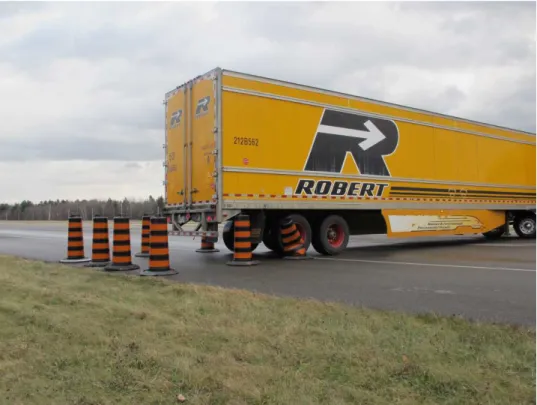
The subject vehicle was positioned on the test track and remained stationary for the duration of the test. The target vehicle was positioned in an adjacent lane, leaving roughly 1.5 m of lateral clearance between the two vehicles. A laser distance meter was attached to the rear of the subject vehicle trailer to continuously measure the clearance distance between the rear of the trailer and a laser reflection panel mounted to the target vehicle. The target vehicle with the laser reflection panel may be seen in Figure 20. The laser reflection panel structure may be seen in Figure 21. The white panel in the right of Figure 21 was used to reflect the laser. The orange cone affixed to the structure was used along with the painted yellow line to maintain the separation distance between the target and subject vehicles.
Once the target and subject vehicles were in position, the target vehicle was driven slowly (<5 km/h) back and forth alongside the subject vehicle. The test subject was instructed to activate a pendant switch every time they perceived that the rear of the subject vehicle’s trailer was flush with the front of the target vehicle’s nose. The rearward and forward position of the target vehicle may be seen in the upper and lower images of Figure 22. The middle image of Figure 22 shows the position in which the test subject was asked to activate the pendant switch. The target vehicle continued driving forward and backward for a total of 20 minutes.
The same procedure was followed for both driver side and passenger side positioning of the target vehicle, daytime and nighttime conditions and with both the camera-based and mirror-based indirect vision systems.
Upon completion of the quasi-static lane change test, the test subject was provided with brief questionnaires to collect additional data. The quasi-static lane change test questionnaires may be found in Appendix G and Appendix H.
March 31, 2014 National Research Council of Canada Automotive and Surface Transportation
Revision B
Figure 20: Laser reflection panel mounted to target vehicle
ST-GV-TR-0015 Page 23
March 31, 2014 National Research Council of Canada
Automotive and Surface Transportation
Revision B
March 31, 2014 National Research Council of Canada Automotive and Surface Transportation
Revision B
4.5 Dynamic Lane Change
The dynamic lane change test was performed at the Transport Canada test track in Blainville, Québec. The purpose of the dynamic lane change test was to compare the ability of the driver to perform lane change maneuvers with each of the tested indirect vision systems. The test was performed both with the conventional mirror-based indirect vision system as well as the camera-based indirect vision system during daytime and nighttime lighting conditions. Although weather was not a controlled factor, all tests took place in precipitation free conditions.
Two test speeds were used for the target vehicle: 40 km/h and 74 km/h. The test speed of 74 km/h was chosen as the target vehicle’s cruise control could only be set to 2 km/h
increments. The subject vehicle’s passing speeds were 50 km/h and 80 km/h, the latter being the nighttime speed limit of the test track.
To begin the test, the target vehicle was brought up to test speed, followed by the subject vehicle being operated by the test subject. Once at the test speed, the target vehicle engaged its cruise control to maintain that speed during the lane change manoeuvre. Once the target vehicle was locked into the test speed with the cruise control system, the subject vehicle passed the target vehicle and performed a lane change in front of the target vehicle. Three attempts at the lane change manoeuvre were performed on both the passenger side and the driver side of the target vehicle, at 40 km/h and 74 km/h target vehicle speeds, and during both daytime and nighttime driving conditions.
To measure the separation distance between the two vehicles at the time of the lane change, a laser distance meter was affixed to the side of the target vehicle. For lane change manoeuvres with the subject vehicle passing on the passenger side of the target vehicle, the laser was affixed to the passenger side of the target vehicle. For lane change manoeuvres with the
subject vehicle passing on the driver side of the target vehicle, the laser was affixed to the driver side of the target vehicle. The laser affixed to the passenger side of the target vehicle is shown in Figure 23 and Figure 24. In order to provide a sizeable target with suitable reflective
properties on the rear of the subject vehicle’s trailer, large white reflection panels were affixed to the rear of the trailer. The laser reflection panels may be seen in Figure 25.
The effective range of the laser distance meter was 15 m. When the clearance distance between the two vehicles was greater than 15 m, the GPS units located on the vehicles were used to determine the clearance distance during lane change manoeuvres.
Upon completion of the dynamic lane change test, the test subject was provided with brief questionnaires to collect additional data. The dynamic lane change test questionnaires may be found in Appendix I and Appendix J.
ST-GV-TR-0015 Page 25
March 31, 2014 National Research Council of Canada
Automotive and Surface Transportation
Revision B
Figure 23: Laser distance meter affixed to the side of the target vehicle
March 31, 2014 National Research Council of Canada Automotive and Surface Transportation
Revision B
ST-GV-TR-0015 Page 27
March 31, 2014 National Research Council of Canada
Automotive and Surface Transportation
Revision B
4.6 Evasive
Manoeuvre
The evasive manoeuvres test was performed at the Transport Canada test track in Blainville, Québec. The purpose of the evasive maneuvers test was to assess the ability of the vehicle operator to determine whether a lane change could be successfully completed in the event of a sudden and unforeseen road obstruction. The test was performed both with the conventional mirror-based indirect vision system as well as the camera-based indirect vision system during daytime and nighttime lighting conditions. Although weather was not a controlled factor, all tests took place in precipitation free conditions.
The test subject was informed that they would be driving at 80 km/h with the indirect vision system under test deactivated. The test subject was instructed that once the indirect vision system was activated, they were to decide whether they felt they could perform an evasive lane change maneuver. At the same time of indirect vision system activation, the test team told the test subject to “move left” or “move right”, dependent upon where the target vehicle was located. If the test subject felt a lane change could be performed safely, they were to provide steering input to the subject vehicle in the required direction. The test subject was not asked to perform a full lane change to avoid a possible collision in the event there was insufficient clearance distance between the subject and target vehicles. They were merely asked to show intent of a lane change manoeuvre.
There were six predetermined locations for the target vehicle, as shown in Figure 26. The test subject was not informed as to the number or location of test positions. Test positions one, three and five are shown in Figure 27.
With the subject vehicle leading the target vehicle, both vehicles accelerated to test speed. Once at test speed, the target vehicle positioned itself in one of the six test positions. Once in position, the indirect vision system under test was activated and the test subject was asked to make the decision as to whether or not they should perform a lane change manoeuvre. Ten tests were performed for each of the four test conditions: mirror-based indirect vision system during the day, mirror-based indirect vision system at night, camera-based indirect vision system during the day and camera-based indirect vision system at night. The order in which the tests took place may be found in Table 6.
Upon completion of the evasive manoeuvre test, the test subject was provided with brief questionnaires to collect additional data. The evasive manoeuvre test questionnaires may be found in Appendix K and Appendix L.
March 31, 2014 National Research Council of Canada Automotive and Surface Transportation
Revision B
Figure 26: Evasive manoeuvre target locations
Table 6: Target vehicle positions for evasive manoeuvre test
Test
Target Vehicle Positions (Camera Tests)
Target Vehicle Positions (Mirror Tests)
Day Night Day Night 1 3 3 3 4 2 3 5 3 3 3 2 4 5 4 4 6 5 1 5 5 2 4 6 1 6 4 6 2 1 7 5 4 3 5 8 1 2 4 4 9 6 1 2 6 10 3 1 6 2