by
GEORGE C. ALLEN, JR.
Submi.tted in Partial Fulfillment of the Requirements for the
Degree of Master of Science
at the
Massachusetts Institute of Technology May, 1971
Signature of Author
Departmeht of Nuclear Engineering May 14, 1971
Certified by_
jt Thesis ervisor
Accepted by
Chairman, Departmental Committee on GraduAte Students
Archives
As. IST.Trc7EJUN 15 1971
by
George C. Allen, Jr.
Submitted to the Department of Nuclear Engineering on
May 14, 1971, in partial fulfillment of the requirements for the Degree of Master of Science.
ABSTRACT
The design version of the Massachusetts Institute of Technology reasearch reactor (MITR-II) was analyzed subject to earthquake forces. The problem was divided into three major areas.
First, the reactor core tank and support structure were studied. The reactor can be adequately cooled and shutdown if the core tank remains undamaged. Using a SABOR-5 compiter program, the peak accelerations required to cause yielding
of the core tank were calculated to be well above potential
earthquake accelerations.
Second, the possibilities of potential damage to
mis-cellaneous reactor systems were studied, The mismis-cellaneous systems were studied to see if earthquake accelerations, re-sonance response, or differential motions would result in damage leading to major radioactive releases. No major potential hazards were discovered.
Third, the possibility of earthquake damage to the re-actor stack was studied. An approximate analysis of the
stack subject to dynamic earthquake shear and a 100 mile per
hour wind was made. A case of a fallen stack was modeled to
determine its efect on the containment building. The
con-servative calculations indicate that it is unlikely that the
stack will fall and even if it were to fall onto the con-tainment shell, it would not cause damage to the reactor core tank.
Within the scope of this report, it appears that the design MITR-II is adequate to provide required protection even in the event of the maximum expected earthquake motions.
Thesis Supervisor: David D. Lanning
ACKNOWLEDGEMENTS
The author wishes to express sincere appreciation for the assistance of his thesis supervisor, Professor David D. Lanning. He would also like to thank James Kotanchik who made available the results of several SABOR-5 computer code
calculations. The author also thanks Edward Barnett and the reactor operations staff for their assistance.
The author would also like to acknowledge the valuable assistance of Professor J. M. Biggs and Professor R. J.
Hansen of the Department of Civil Engineering, and the advice of Professor E. A. Witmer and Barbara Berg of the Department of Aeronautics and Astronautics. He is also grateful to Chris Ryan for loan of a Schaevitz accelerometer. Special thanks
go
to Miss Schmidt for her help in preparation of this document.Many of the calculations in this thesis were made using the System 360/M65 of the M.I.T. Computation Center.
TABLE OF CONTENTS
Page
Chapter 1. Seismology and Method of Analysis 10
1.1 Introduction 10
1.2 History of Earthquakes 10
1.3 Earthquake Zone and Return Period 12
1.4 Local Soil Conditions at the MITR-II Site 12
1.5 Analysis of the MITR-II 14
Chapter 2. Analysis of the MITR-II Core Tank 24
2.1 Introduction 24
2.2 Summary of Loads 24
2.2.1 Inner Vessel Loads 27
2.2.2 Outer Core Tank Loads 28
2.2.3 Calculational Model 29
2.3 Description of the SABOR-5 Computer 31
Program
2.4 Outline of Analysis 32
2.5 Results of the Calculations 35
2.6 Determination of the Fundamental 40
Frequency of the Water-Filled Core Tank
2.7 Analysis of Results 41
Chapter
3.
General Areas of Seismic Interest in 45MITR-II
3.1 Introduction 45
3.2 Reactor Floor Design Loadings 45
Page
3.3 Piping 49
3.4 Seismic Effect on Control Rods 50
3.4.1 Description of Control Rod 50
Assembly
3.4.2 Drop Time 51
3.4.3
Rod Whip During an Earthquake54
3.5 Building Penetrations
58
3.6
Seismic Instrumentation 643.7 Temporary Shield Walls 67
Chapter 4. Reactor Stack 69
4.1 Introduction 69
4.2 Approximate Earthquake Analysis of 69
Stack
4.3 Worst Case of Stack Failure 74
4.3.1 Load Model 74
4.3.2 Calculational Model 74
4.3.3 Local Buckling of Roof 78
4.3.4 Results of SABOR-5 Analysis 78
4.4 Summary 80
Chapter
5.
Summary 82Appendix A - SABOR-5 Results of the Reactor Vessel 84
Appendix B - Fortran IV Computer Loads Program used 89
on the Inner Flow Shroud
Appendix C - Fortran IV Computer Loads Program used 96 on the Outer Core Tank
Appendix D - Fortran IV Computer Program used in Determination of Fundamental Frequency of Core Tank
Appendix E - Calculation of Fundamental Mode of Coolant Pipe
Appendix F
-Appendix G
-Appendix H
-Calculation of Guide Tube
Dis-placement from 1 g acceleration
Fortran IV Computer Program for Approximate Stack Analysis
References Page 102 109 ill 113 117
I
LIST OF FIGURES
Figure No. Page
1.1 Relations between intensity scales and 16
acceleration
1.2 Seismic Probability Map of the United 17
States I
1.3 Seismic Probability Map of the United 18
States II
1.4 Seismic Probability Map of the United 19
States III
1.5 Earthquake Intensity - Acceleration 20 Relationships
1.6 Contour Map of Accelerations as a Percent 21 of g with 100 year return period
1.7 Contour Map of Return Period in Years for 22
Acceleration of 0.1 g
1.8 MITR-II Site Plan 23
2.1 Outer Core Tank 25
2.2 Inner Vessel and Flow Shroud 26
2.3 Orientation of Theta Positions of Core 37
Tank Support
2.4 Calculated SABOR-5 Stresses 38
3.1 Reactor Floor Design Loadings 46
3.2 Simplified Representation of MITR-I Lattice 47
3.3 Control Rod Assembly 52
3.4 Rod in Control Rod Guide Tube
54
3.5
Model of Control Rod Displacement57
Figure No. Page
3.7 Accelerometer Signal Circuit 65
3.8 Accelerometer Output 66
4.1 Fallen Stack Zones 73
4.2 Model of Fallen Stack 76
4.3 Element Divisions of the Containment Roof 77
A.1 Freebody Diagram of Core Tank 86
LIST OF TABLES
Table No. Page
2.1 Limiting Accelerations on Core Tank
39
3.1 Approximate Reactor Floor Loading from 48 Lattice
3.2 Building Penetrations 61
4.1 Shear Stesses in Stack ?l
4.2 Loads Used in Fallen Stack Problem 75
4.3 Stresses on Containment Roof from Fallen 79 Stack
A.1 Static Case Comparisons of Calculations 85
A.2 Comparison of Static SABOR-5 Case with -85 Free-body Diagram
A.3 Inner Vessel Stress 87
A.4 Outer Vessel Stress 88
Chapter 1
SEISMOLOGY AND METHOD OF ANALYSIS
1.1 INTRODUCTION
Earthquakes must be considered in the design of nuclear reactors, even in the New England area. Most earthquakes in New England pass without being noticed, for there are no less than several thousand minor earthquakes each year. The Massachusetts Institute of Technology research reactor
(MITR-II) located in Cambridge, Massachusetts must be able to withstand earthquake motion without endangering the local populace. This work is an evaluation of major aspects of a seismic study of MITR-II.
The remainder of this chapter will cover the history of earthquakes in the Boston area and the seismic probability of the site area. The last section of this chapter will explain the seismic analysis sequence of MITR-II.
1.2 HISTORY OF EARTHQUAKES
The Cambridge area lies in the Boston Basin which has been relatively free of earthquakes in recorded times.(Sl). The United States Department of Commerce in Earthquake
History of the United States (H2) has the following to say
about Massachusetts.
"In addition to feeling some of the more severe
Canadian earthquakes and the New York and Grand Banks
quakes of 1929, 17 (of intensity
5
and over on the Rossi-Forel scale) are listed for this state. In colonial times there were a large number of earthquakes in the northeast part of the state near Newburyport, and several of these,especially that of 1727 (75,000 square miles), were widely
felt. That of 1755, near Boston, was felt over an area of 300,000 square miles. The shock of 1925 in the vicinity of Boston was strong. Numerous moderate shocks have been felt
in the southeast part of the state."
Massachusetts earthquakes of Rossi-Forel intensity of seven or greater in Earthquake Damage and Earthquake Insurance
by John R. Freeman (Fl) as follows:
Date Location Rossi-Forel
Intensity 1638 Plymouth, Mass, 8 1662 Boston, Massachusetts 8 1727 Newburyport, Mass. 8 1744 Newburyport, Mass. 8 1755 Boston, Massachusetts 9 1817 Woburn, Massachusetts 8
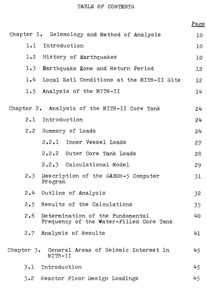
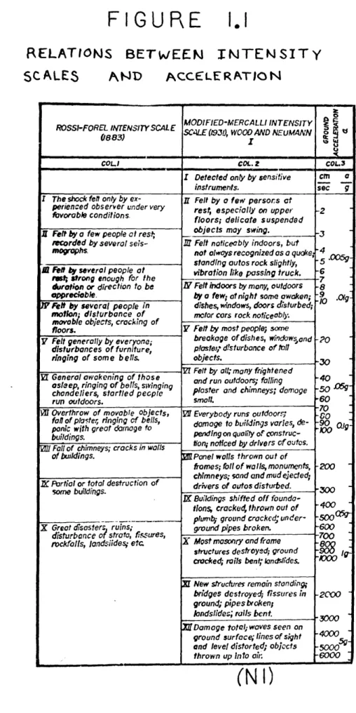
An explanation of the Rossi-Forel scale and a correlation with the Modified-Mercalli intensity scale is found in
Figure 1.1. Historical accounts of Boston area earthquakes
during 1727-1755 included such phrases as (Hl):
"...many chimneys were leveled with the roofs of the houses, and many more shattered and thrown down in parts..."
"...the gable ends of some brick buildings (were) thrown
down and others cracked..."
"...(strong motions) continued about two minutes..."
1.3 EARTHQUAKE ZONE AND RETURN PERIOD
At the present time there is no standard Seismic Risk or Probability Map available on the United States that an engineer is required to follow. Such maps do however give a feel for the potential damage or expected maximum intensity
in a given area. Examples of three Seismic Risk maps are shown in Figures 1.2, 1.3, and 1.4. From these maps, the Cambridge MITR-II site appears to be in a region of moderate potential earthquake damage and have a maximum earthquake intensity of about 8 on the Modified-Mercalli scale. The relationship between Modified-Mercalli intensity and
accel-eration is shown in Figure 1.5.
A different representation of earthquake activity is
shown by the use of return periods (approximate frequency) of various accelerations in Figures 1.6 and 1.7. The pre-dicted return period for a 0.1 g. earthquake (equivalent to VII on the Modified-Mercalli scale) for a Cambridge site would be approximately 1,000 years according to the maps of Milne and Davenport (1969).
1.4 LOCAL SOIL CONDITIONS AT THE MITR-II SITE
The average soil conditions at the site are about 11 feet of miscellaneous fill overlying from
5
to 10 feet of soft organic silt and peat. Immediately below are approxi-mately 10 feet of hard, medium to fine sand and gravellying above more than 100 feet of Boston blue clay. The
reactor building and adjacent stack, as shown in Figure 1.8, are on reinforced concrete mats founded on the hard sand and gravel (Al).
In general, earthquake motions are amplified and other-wise modified by near-surface geological features. At other
locations, in a study by Tamura (Hl) it was found that the peak acceleration at ground surface was about twice the peak acceleration at a depth of 300 meters (the same trend of
in-creased motion from depth up to the surface occurred for both a deposit of soil and rock). Based on the assumption
that most ways of estimating ground motions really apply for a very dense hard alluvium or for soft rock, Newmark and Hall suggested site factors to modify earthquake motions to make
them apply for very soft ground or hard rock (Hl). Newmark's Site Factors
Soft Ground 1.5
Firm soil - Soft rock 1.0
Hard rock 0.67
The MITR-II is located on soft ground. Assuming a reasonable design peak acceleration of 0.15 g. based on the area history and on the predicted return periods (Boston Edison's Plymouth Nuclear Power Station used approximately
0.15 g. as its design peak acceleration) and applying
New-mark's site factor of 1.5, the estimated design peak earth-quake acceleration at the MITR-II site would be 0.225 g.
1.5 ANALYSIS OF THE MITR-II
The reactor shield is an integral unit with the
remainder of the building. The building rests on a 70
foot diameter, 3 feet thick, heavily reinforced concrete pad. It is expected that the shield and pad will shift as a unit rather than cracking under seismic shock. On a more quantitative basis, a careful review of the seismic effects on the MITR-II has been made with the assistance of Professor Robert J. Hansen and Professor John M. Biggs from the Civil Engineering Department of MIT. Based on their experience with seismic effects, (Hl) it was concluded that the support for the main core tank of the MITR-II will not lose its
structural integrity and hence will always be able to support the core tank. As shown in the MITR-II Safety Analysis
Report (Sl), the reactor can be shut down by insertion of independently acting shim blades or by backup shutdown action of dumping the D 0 reflector. It has also been shown in the
2
MITR-II Safety Analysis Report that the core will be ade-quately protected as long as H 0 remains in the tank for
2
natural convective cooling after the controls actuate to shut the reactor down. One problem which is particularly severe in regions of high seismic activity in the western United States but can be ignored for the MITR-II site, is the possibility of fault displacement through the site (Hl),
analysis to determine the earthquake forces that would be required to cause a yield stress in the core tank itself. The core tank is analyzed for the operating case with the
D20 reflector dumped, being subject to various accelerations.
Chapter III discusses a study of seismic effects on several reactor systems such as control rods, miscellaneous piping, building penetrations, and floor loadings.
Chapter IV is seismic study of the brick stack adjacent to the reactor building.
Chapter V is a summary and list of potential recommend-ations.
FIGU RE
I.
RELATIONS BETWEEN INTENSITY
SCALES AND ACCELERATION
9
ROSSI-FORELiNTENSITYSCALE MODIFIED-MERCALLI INTENSITY SC4LE (1930, WOOD AND NEUMANN
COLI COL.2 COL3
I Detected only by sensitive cm a
instruments. sec g
I The shock felt only by ex-perienced observer under very favorable conditions.
Z Felt by a few people at rest;
recorded by several seis-
mogrophs-il Fel by several people at rst; strong enough for the
duraton or direction to be
oppreciable.
)V1ft by sevaral people in
motion- disturbance of movable objects, crack ing of floors.
V Felt generally by everyone;
disturbances of furniture, ringing of some bells. VT General awakening of those
asleep, ringing of bells, sivinging
chandeliers, startled pepl run outdoors.
V1 Overthrow of movoble objects, fal of plaster ringing of bells, pnic with great damage to buildings.
0f Fall of chimneys; cracks in walls of buildings.
X Partial or total destruction of some buildings.
X Great disosters ruins;
disturbance adstrata, fissures,
rockfolls, Iandsiides etc
IT Felt by a few persors at rest, especially on upper
floors; delicate suspended objects may swing.
Z Felt noticeably indoors, but not always recognized as a quoke; standing autos rock slightly,
vibration like passing truck.
N Felt indoors by many, outdoors by a few; o night some awaken; dishes, windows, doors disturbed; motor cars rock noticeably.
V Felt by most people; some breakage of dishes, windowsand
plasteq disturbance of toll
objects.
Vt Felt by oll;many frightened and run outdoors; falling ploster and chimneys; damage
small.
Of Everybody runs outdoorr; damage to buldings varles, de-pending on quality of construc-tion; noticed by drivers of autos. M Panel walls thrown out of
frames; foil of walls, monuments,
chimneys; sand and mud ejected;
drivers of autos disturbed.
IX Buildings shifted off foundo-tions, cracked, thrown out of
plumb; ground crockcd; under-ground pipes broken.
X Most masonry and frame structures destroyed; ground cracked; rails bent; londslides.
3E New structures remain standing; bridges destroyed; fissures in ground; pipesbroken; landslides; rolls bent. Xff Damage total; waves seen on
ground surface; lines of sight end level distorted; objacts thrown up Into air
-2 -3 -4 -5 7 -8 .9 .1O .005- .O1g-20 30--40 ~ -60 -70 90 0/~ 200 -300 -400 -600 2000 3OOO -5000 5 -6000
(NI)
FIG
U R E
ZONE 0- NO DAMAGE ZONE I - MINOR DAMAGE ZONE 2 - MODERATE DAMAGE
ZONE 3 -MAJOR DAMAGE
SEISMIC PROBABILITY MAP OF THE UNITED STATES I
1.2
H
ZONE 0- NO DAMAGE
ZONE I -MINOR DAMAGE ZONE 2 -MODERATE DAMAGE ZONE 3 -MAJOR DAMAGE
SEISMIC
PROBABILITY
MAP OF THE UNITED
STATES
II
V
AUGUST 1958Seismic Regionalizobion, U S A
showing zones of given probable
moximum intensity M. M.
C F Richter
SEI5MIC PROBA\BILITY
ANP OF THE UNITED STATES-III
(HI)
H
F
G U R E
I. 5
I IEx
WYzY
II I x x EQUIVALENT MM INTENSITY A-HERSHBERGER (1956) B-GUTENBERG 8 RICHTER (1942) *C- CANCANI (1904) *D- ISHIMOTO ( 1932) *E-SAVARENSKY a KIRNOS (1955)**DATA COMPILED BY WESTON GEOPHYSICAL ENGINEERS *F- MEDVEDEV ET AL. (1963) *G-N.Z. DRAFT BY-LAW H-TID-7024 (1963) *1-KAWASUMI (1951) *J-PETERSCHMITT (1951)
* DATA FROM G. A. EIBY (1965)
1000 500 100 50 w 0 z 0 w -1 w 5 1.0 0.5
(H I)
I
CONTOUR MAP OF ACCELERATIONS AS A PERCENT OF
OF g WITH A 100 YEAR RETURN PERIOD FOR EASTERN
CANADA (from Milne and Davenport, 1969)
ZN) H
CONTOUR MAP OF.RETURN PERIOD IN YEARS FOR ACCELERATION 'OF 0.1 g IN EASTERN CANADA
MA/I /Vf yt. R. e OS T O 0 A L B8 A N Y 51,NA A - "a.%res f225-an, ~___________ A L B A N Y c" " s . ... - -/2s 0/' - -- ~ ___ ___ _ - -__ A S T R E E T ,,, 11Y-- 74 -\. SITE PLAN N)
Chapter 2
ANALYSIS OF THE MITR-II CORE TANK
2.1 INTRODUCTION
The critical component of the MITR-II subject to seismic effects is the reactor vessel. Because of the extremely rigid structure supporting the reactor vessel, earthquake motion of the reactor vessel supports will be similar to soil motions at the foundation mat of the reactor building. The reactor can be maintained in a safe condition and the fuel adequately cooled if the core tank is not dam-aged and remains filled with water. Considering the reactor core tank as the critical component to be maintained, inde-pendent of the need of the outer containment building; failure of the stack or mechanical support facilities from earthquake motion can be tolerated, even in the unlikely case of the
stack falling and hitting the outer containment building.
2.2 SUMMARY OF LOADS
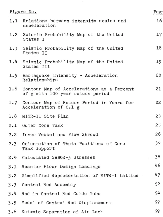
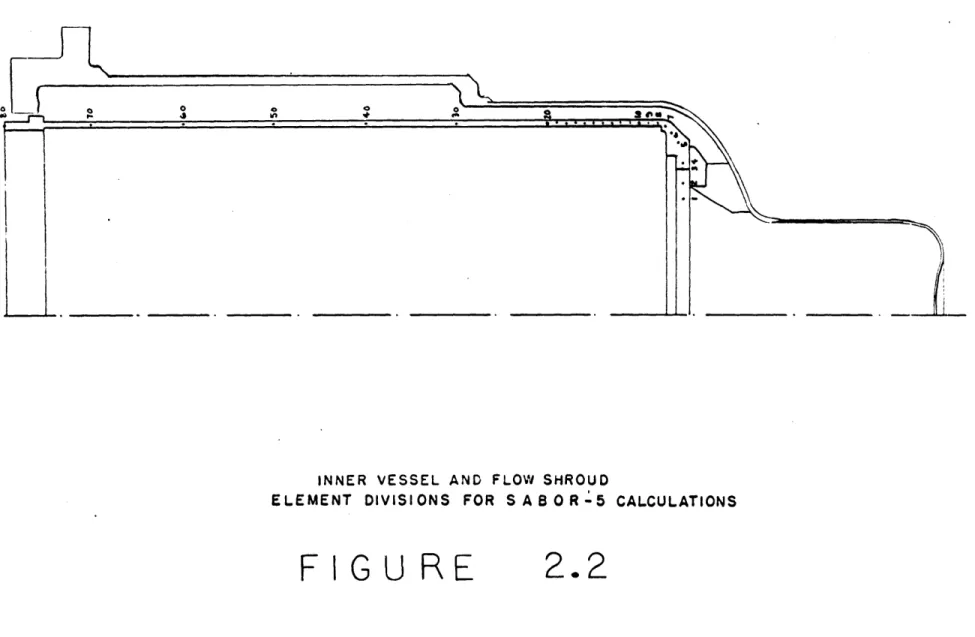
The configuration of the reactor core tank is shown in Figure 2.1 and the configuration of the inner vessel (flow shroud) is shown in Figure 2.2. Studies have been made of both the H 20 outer core tank and the inner vessel, including
the flow shroud, to determine stress levels in each structure in terms of several loading parameters.
The complete set of loads consists of a gravity load
S
OUTER CORE TANK ,
ELEMENT DIVISIONS FOR SABOR-5 CALCULATIONS
and horizontal seismic motion of the structure. For all cases, the vertical acceleration was set at 2/3 of the horizontal level, following the suggestion of Professor Hansen of the MIT Civil Engineering Department. The
dis-cussion of the loads given below will be divided into two sections: (1) loads for the inner vessel; and (2) loads
for the outer core tank.
2.2.1 Inner Vessel Loads
The loads associated with the inner vessel and flow shroud must be considered in terms of its geometry. The
fuel element hexagonal container is porous and hence no water inertial loads are acting upon it. The support ring of the fuel element container will be subject to water and structural inertial loads only, but no hydrostatic loads
since both the inner vessel and outer core tank are connected. Loads on the vertical section of the flow shroud are due to the inertia of the metal itself and the inertial loads due to the contained water. These inertial loads can be
char-acterized by the expression (for the horizontal component). F = R i. cosS -9005 < 900
w l
= 0 900 2700 (2.1)
where
e'
= density of waterRi = inside radius of the inner vessel (9 = angle measured from the direction of
horizontal motion. (The orientation of
is shown in Figure 2.3).
4 terms of a Fourier cosine series which yields the expression:
F = 0.31831
e
R. + 0.5e
R. cosO + 0.21221e
R
cos 2fw i w 1w
- 0.04244 e R cos 4(
w (2.2)
This form returns 99% of the peak load and is an adequate representation of the load for this study.
The effect of the various loads have been calculated by using a computer program SABOR-5 (K2).
For convenience in running the SABOR-5 program, a small program was written to generate a set of loads as the input
for SABOR-5. A listing of this program is included in Appendix B.
When SABOR-5 is run for the inner vessel, the program considers the nodes at which the inner vessel is supported
by the outer core tank to be restrained, and it calculates
a set of forces to be applied to the outer vessel at the
corresponding outer vessel nodes.
The effect of the fuel elements and their supporting material is included by considering that portion of the structure as a lumped mass at its center of gravity, and equivalent ring loads are calculated and applied at the edge
of the support flange.
2.2.2 Outer Core Tank Loads
Because of the narrow clearance between the flow shroud and the core tank, water inertial loads resulting from side-ways motion are neglected. In the lower portion of the
vessel, the contribution of the water inertial load is
small, (due to the small local radius and the large portion occupied by the core) and can be neglected in comparison to the loads due to the very large contribution from the up-ward motion and the hydrostatic head.
For the core tank, a small program was again written to provide the input to SABOR-5. A listing of this program is included in Appendix C.
2.2.3 Calculational Model
The reactor vessel is composed of two major components, the outer core tank and the inner flow shroud. In the cal-culational model, the outer core tank was divided into 94 finite elements and the inner flow shroud was divided into
79 finite elements. The stress on each of these elements
was determined by using the SABOR-5 computer program. These elements are shown in Figures 2.1 and 2.2.
Several problems were encountered in the modeling and in the calculation of loads. Primary among these is the problem associated with the support geometry between the
inner vessel and the outer core tank. The physical support consists of 12 feet equally spaced circumferentially between the inner and outer vessel. This construction introduces physical asymmetry into the geometry and since SABOR-5
handles asymmetric geometries only with great difficulty,
some study of the modeling of the structure in that area was made.
SABOR-5 models all geometries as axisymmetric structures. Local asymmetries are modeled by "smearing" the structure in that local area. For structural elements such as the twelve supporting feet, the SABOR-5 program would generate results for a continuous ring between the inner and outer vessels (equivalent to increasing the metal density by appropriate amounts for the elements in the feet area). But in this model, serious errors can result in the calculated local stress distribution in the area where the feet rest upon the outer core tank, and for this reason a detailed study of this problem was undertaken.
For this detailed study, the SABOR-5 calculated loads
at the feet of the inner vessel were lumped into values at each of the twelve feet and a higher order Fourier series loading for the outer core tank was computed from them. Harmonics 0, 1, 11, 12, 13, 23, 24, 25, 35, 36 were used. This representation of the load at the feet was within 5% of the exact value, and the load midway between the feet was negligible. The local stress distribution in the region of
feet on the outer vessel was then computed. The values ob-tained were compared with those of the continuous mode. This comparison yielded the result that the peak stresses were nearly 50% greater than those obtained from a continuous model of the support loads.
located near the bottom center of the tank and in the feet area at the element above the feet. Thus to be conservative, the feet area stresses reported in AppendixAare the maximum stresses in the feet area calculated using the continuous case and increased by a factor of 60%.
2.3 DESCRIPTION OF THE SABOR-5 COMPUTER PROGRAM
The analysis by using the SABOR-5 Computer Program
treats linear-elastin, static, load-deflection behavior of
meridionally-curved, variable thickness double - and/or single-layer, branched thin shells of revolution which may be subjected to concentrated or distributed external mech-anical and/or thermal loads. In the present analysis, it
is assumed that the structure is axisymmetric in terms of both geometry and material properties; hence, when the structural deformations are expressed as sums of Fourier harmonics of the circumfetential coordinate
e
,
the equili-brium equation for the structure consists of a set of har-monically-uncoupled load-displacement equations (ie.,there is a separate set of equations for each harmonic of the structural response).(Kl). The harmonic deflection coefficient may be determined by solving these equations for each significant loading harmonic present, and may then be summed to obtain the complete deformation. The require-ment of material axisymmetry means that while nonuniform and/or asymmetric temperature distributions may be treated,
the material properties, E, ,C, must be independent of the local temperature, but more precisely independent of location
2.4 OUTLINE OF THE ANALYSIS
The application of the discrete-element procedure may be divided into three phases: structural idealization, evaluation of element properties, and analysis of the com-plete structure. In the analysis of both the inner and outer vessels, the structures were modeled as single-layer elements.
In the discrete-element formulation, the actual struc-ture is replaced by an assemblage of geometrically-compatible discrete elements. As previously stated, for the present
analysis, the basic discrete elements to be employed are
single-layer. For a single-layer element only four quantities are necessary to fully describe the state of deformation
within an element. These quantities for each element are: (a) Midsurface meridional displacement,A
(b) Midsurface circumferential displacement, V
(c) Normal displacement, W
(d) Total meridional rotation, Jw + pK _)
as CAs
In the above expressions 0 is the meridional slope of the element. One may reduce the number of degrees of freedom necessary to describe the deformation state of each element
to the nodal values of the displacements in each element. Then the choice of a reasonable assumed (analytic) function for the interior displacements, which also includes inter-element displacement compatibility, provides a complete representation of the overall deformation state of the element.
th
At the bounding nodes of the P element (say nodes q and r) let generalized forces Qi, q ... Qn' q, Qi,r
Qn, r (where n=4 for single-layer elements) be defined
corresponding to the generalized displacements at the node. The application of the Principle of Stationary Total Potential Energy yiblds the equations for static equilibrium for the Pth element; as a consequence df the condition of structural axisymmetry, these force-displacement relations are harmoni-cally uncoupled. In matrix form, the force-displacement relation for the
jth
harmonic A-series Fourier displacement component becomes:Kpj) 4
where
f
Kp 0) is the element stiffness matrix. Imposition of nodal compatibility at interior nodes of the complete structure requires that at an interior node r, bounded byelements p and q the following relationship must be satisfied:
qi, r ql, r
q 29r q2,r
(2463)
q n r gn, r
The total potential energy (Tr ) for the n discrete p
elements, including the strain energy as well as the
potential energy of all of the virtual-work-equivalent
nodal loads (for both distributed and ring loads), and the
imposition of nodal compatibility then becomes expressed in terms of the N independent nodal displacement of the complete assembled discretized structure. The equilibrium equations for the entire structure are then obtained by setting
'TTP
= 0, where only displacement variations arepermitted. For the
jth
harmonic A-series Fourierdisplace-ment harmonic, for example, these read:
K(J f q(i) I =
2
k1 p( ) (2.4)Nx N Nx1 Nxl
In the above equation, N is the total number of degrees of freedom associated with the complete structure, and the ith term F of the generalized force vector is the sum of all the
jth
harmonic generalized forces from all theindiv-idual discrete elements and from the
jth
harmonic general-ized ring-type loads, both of which are associated with ith degree of freedom of the complete assembled discretized structure. Also,[K(a)]
represents the (assembled) stiff-ness matrix for the complete structure.For most practical applications, the physical structure will be restrained in some fashion such that one or more generalized displacements will be known before the general solution is obtained. A solution for the complete
displacement field then will not be found from Equation (2.4) but from a reduced equation from which the restrained degrees of freedom have been deleted. The reduced equation
is similar in form to Equation (2.4) and follows:
[K(j)
]
q(j)7
= F(i)j (2.5)(N-R) x (N-R) (N-R) x 1 (N-R) x 1
where R is the number of known or prescribed generalized displacements.
Equation (2.5) may be solved for the unknown-generaliz-ed displacements using any appropriate method. A similar equation may be written for each loading harmonic present. The total generalized displacement may then be found by summing the contributions due to each loading harmonic. Since all of the N displacements are now known, they may be used to determine other information such as:
(a) strains by use of the appropriate strain displace-ment relations and
(b) stresses and/or stress resultants.
The detailed loads programs required to carry out the above - outlined discrete-element analysis for the specific case of the MITR-II reactor core tank and inner flow shroud are included in Appendices B and C. There are no thermal
loadings in our analysis.
2.5 RESULTS OF THE CALCULATIONS
surfaces of each element of the vessels being analyzed for various circumferential theta stations. Comparison of the computer results with hand calculations showed agreement between the two methods (the computer method appears to be the more conservative). This comparison was made for the case of zero acceleration, static operating conditions (Table A.1). SABOR-5 also showed agreement between the static case and freebody stress analysis (Table A.2). On
the basis of this agreement and from previous experience
with the SABOR-5 program as documented in the work by
Witmer and Kotanchik, (Wl) the program is taken to give
valid estimates of the stresses.
Extremely small stresses were calculated to occur in the inner flow shroud (Table A.3), in comparison with the outer core tank. The outer core tank is therefore shown to be the critical part.
The outer core tank has been analyzed for the following four cases:
(a) static operating case (STC)
(b) STC + 0.5 g. horizontal + 0.33 g. vertical
(c) STC + 1.5 g. horizontal + 1.0 g. vertical (d) STC + 4.5 g. horizontal + 3.90 g. vertical
The peak stresses occurred on the inside of station 50 (Figure 2.1). This peak stress is actually the peak stress as given by the continuous case increased by a factor of
F IGU
RE
ORIENTATION OF
@
POSITIONS WITH
RESPECT TO THE DIRECTION OF
ACCELERAT\OM
OF CORE TANK
270*
SUPPORT
2.3
10,000
PEAK STRESSES FROM G -+ 2/3 G
t
(PSI) z4 4 3 a: 2 O--: w 0Table 2.1
LIMITING ACCELERATIONS ON CORE TANK
Horizontal Vertical
Criteria Acceleration Acceleration Peak Stress = working 2.9 g 2.0 g stress limit (6250 psi) Peak Stress = yield 5.1 g 3.4 g stress (9500)
The analysis showed that stress increased linearly with acceleration (Figure 2.4). Thus, by extrapolation of the results to the condition for which the peak stress equals the working stress, and the case where the peak stress equals the yield stress, the limiting accelerations were derived as shown in Table 2.1.
2.6 DETERMINATION OF THE FUNDAMENTAL FREQUENCY OF THE WATER
FILLED CORE TANK
The fundamental mode of the water-filled core tank is determined by a numerical iterative method commonly known as the Stodola and Vianello method (H3). For a structural system the following equation holds.
= w2iEU (2.6)
where
K = stiffness matrix U = displacement matrix
Wi = mass matrix
w = frequency of the mode corresponding to the displacement U Rearranging terms -. U = K i (2.7) letting / = 1 and K= a (2.8) w 2
an equation of the form:
a x x (2.9)
where after assuming an initial displacement, the process is iterated until /) converges on a maximum and thus ob-taining the smallest natural frequency. The mass matrix and stiffness matrix are obtained by running the SABOR-5 pro-gram for the outer core tank. A computer propro-gram was written to convert the SABOR-5 mass and stiffness matrix
to the X-Y-Z coordinate system and to increase the mass
matrix by appropriate lumped masses corresponding to the water in the tank. The program also performs the inversion
of the stiffness matrix and performs the iteration process for an inputed assumed original normalized displacement
(a listing of this computer program is included in Appendix
D.) After 101 iterations the solution had converged on: 24.8 cycles/sec. = 1st mode of water filled
core tank
Thus resonant amplification does not appear to be a problem. (The initial assumed displacements are shown in Figure D.l)
2.7 ANALYSIS OF RESULTS
A detailed analysis has been made to determine the
earthquake forces that would be required to cause a yield stress in the core tank itself. Vector forces on the tank were considered to be largest in the horizontal direction and a force of 2/3 of the horizontal force was simultaneously
applied downward (upward acceleration) in the vertical
direction. The results of these calculations indicate that a combined horizontal acceleration of 5.1 g. and a vertical
acceleration of 3.4 g. will cause a peak stress near the
feet area of the core tank of 9500 psi which is equal to the yield stress limit for the aluminum tank.
It should be noted that these conclusions apply to the reactor structure and reactor core tank. It is conceivable that the effect of an earthquake could cause some damage to the reactor piping or building structure at lower accelera-tions; however, the action of the antisiphon valves would prevent a loss of the necessary H20 coolant in the main
core tank.
A summary of conclusions reached on the seismic effects
has been prepared by Professor Biggs of the MIT Department of Civil Engineering who states that:
"Based upon the seismic criteria commonly used for nuclear power plants, the Design Basis Earthquake for the Cambridge area would probably have a maximum acceleration of about 0.2 g. This estimate considers both the seismicity of the region and the fact that Cambridge is an area of re-latively soft soil conditions.
"The structure supporting the research reactor is a massive, rigid concrete block extending from the bottom of
the foundation to the point of reactor vessel support. Therefore there would be little, if any, amplifications of
the acceleration in the structure itself, i.e., the accel-eration at the reactor support would be essentially the same
as at the bottom of the foundation.
"However, since the support system is a mat foundation on relatively soft soil, a certain degree of soil-structure interaction is to be expected. This tends to increase the fundamental period of the structure and to make the motion of the foundation somewhat different than that occurring in
the undisturbed soil.
"The soil-structure interaction in this case would be almost entirely swaying, or horizontal shearing, in the soil. This type of behavior involves very high damping. As a
consequence, there would be little amplification of the ground acceleration, i.e., the maximum acceleration of the rigid foundation would be essentially the same as that pre-dicted for the ground, or 0.2 g.
"The natural period of the reactor vessel is very short compared to that of the soil-structure foundation system. Therefore, there is no possibility of resonance between the vessel and the supporting structure.
"All of the above leads to the conclusion that the
maximum response acceleration of the reactor could be only slightly greater than the maximum ground acceleration of 0.2 g.
"It has been computed that the reactor is capable of withstanding (at yield stresses) static forces corresponding
to 5.1 g. horizontal acceleration and simultaneously
3.4
g.vertically. It is not conceivable, even under the most unfavorable circumstances, that the response to earthquake motions would be more than a small fraction of these amounts."
Chapter
3
GENERAL AREAS OF SEISMIC INTEREST IN MITR-II
3.1 INTRODUCTION
Many miscellaneous areas of seismic concern exist in a nuclear facility. The following areas of the MITR-II will be covered in this report chapter:
1. Reactor Floor Design Loadings 2. Control Rods
3. Piping
4. Building Penetrations
5.
Seismic Instrumentation6.
Temporary Shield WallsNo problems were discovered that would result in a potential reactor hazard for the design of the MITR-II.
3.2 REACTOR FLOOR DESIGN LOADINGS
Referring to Figure 3.1, a six foot ring around the reactor was designed for a live load of 3,000 pounds per
square foot; and the balance of the floor was designed for
2,000 pounds per square foot. The total design live load of
the floor was 2,000 kips ( 1 kip = 1,000 pounds) and the
lattice facility area of the reactor floor was designed to be fully loaded (F2).
Figure 3.2, shows a simplified representation of the MITR-I lattice facility and the proposed MITR-II lattice facility (the MITR-I lattice facility is decreased in height
GURE
REACTOR
FLOOR
DESIGN
LOADINGS
FtG
U R E
3.2
SIMPLIFIED
REPRESENTATION OF LATTICE
K
3
ORDINARY CONCRETE
150 lb,/ 3
KY
LATTICE
PROPOSED
HEIGHT
uJ
V
z
0
u
X~
GO En -g NwU
-3
4
mf N Nby six feet). The maximum local loading and the approximate total load for both the MITR-I and the proposed lattice fac-ility are shown in Table 3.1.
Table 3.1
LATTICE FACILITY LOADS
Maximum local Approximate total load (kips) load (kips)
MITR-I Lattice 4.725 700
Proposed Lattice
Facility 3.825 550
While the loads due to both structures are well within the total design live loads, and the probability of other areas being fully loaded is very small, both lattice
facil-ities yield local loads above the design 3,000 pound per square foot (psf) within six feet of the reactor and 2,000 psf beyond six feet from the reactor. During construction of the MITR-I lattice facility, careful measurements of the reactor floor were made to determine any deflections of the floor because of the lattice loading. No measurable deflec-tion was found.
While the reactor floor has shown no signs of yielding or deflecting under the MITR-I lattice facility loading
(which is not surprising because of the generous conservatism shown in designing the reactor building (F2)), it is
difficult to predict how much more additional loading the floor could safely take in that area, because it is already loaded at about twice its design value. However, for the proposed MITR-II lattice facility, it can obviously be stated that the floor area in the vicinity of the lattice facility will take a 25% increase in load without damage, because the reactor floor had safely supported the MITR-I lattice facility
(Load MITR-I Lattice = ( 1 + 0.25 ) Load proposed MITR-II Lattice). The proposed lattice floor area will in effect, have been tested for a 0.25 g. vertical acceleration by the experience with the MITR-I lattice. A vertical acceleration of 0.25 is greater than the peak potential vertical accelera-tion. Horizontal earthquake motions are resisted by steel bands around the lattice facility.
In any event, although failure of the reactor floor in the area of the lattice facility might cause damage to the primary system piping in the equipment room, there would be no damage to the core tank or the core tank supporting
structure.
3.3 PIPING
The piping systems in the MITR-II reactor have short period fundamental modes, well above the normal earthquake frequencies. The longest unrestrained run of a major pipe is the light water coolant pipe which runs from the equipment room to the core tank (the pipe is actually restrained
against large motions by the compactness of the area through which it passes). The first fundamental mode of this pipe
is 97 cycles per second (Calculation is in Appendix E). Resonance response of the piping appears unlikely.
The need for flexibility in piping to accommodate
thermal movement provides sufficient flexibility for differ-ential movements of equipment during earthquake motions. It is recommended that consideration be given to lateral re-straints of small piping in the following systems to assure
that adequate seismic restraints are provided: 1. Ion Exchange Unit
2. Heavy Water Cleanup System
3.
City Water Pipe4. Helium supply system to D20 gas holder
5.
D20 Sampling systemWith the restraint of the above systems, the piping does not appear to be a major concern because of short runs, numerous restraints, and low pressures.
3.4 SEISMIC EFFECT ON CONTROL RODS
3.4.1 Description of Control Rods Assembly
The control rod assembly is shown in Figure 3.3. The absorber blades travel in slots in the core housing with a nominal 1/16 inch clearance all around. The blade is
off-set, attached to a magnet armature rod that moves in a slit cylindrical guide tube. Analysis will be made of the
in-crease in rod drop time from seismic motion, rod whip during
earthquake motion, and the blade displacement from a 1g.
lateral acceleration.
3.4.2 Drop Time
In the MITR-II, scram is accomplished by interrupting-an electric current to the magnets by which the rods are suspended so that the rods are free to fall in their guide tubes. If these guide tubes can be considered frictionless, lateral forces will be unimportant (lateral forces will be considered in Section
3.4.3).
Suppose a scram is initiated during an earthquake that is causing the entire reactorstructure to vibrate in the vertical direction with a period on the order of 0.1 or 0.2 seconds and with acceleration
varying accordingly (t .1 g., which is typical of strong-motion earthquakes as recorded by vertical component seismometers)
(Nl). When the current breaks, the control rod, along with the reactor, will have either upward, downward, or zero
velocity with respect to the earth's mass as a whole. Since the magnitude of the vertical ground displacement in typical strong-motion quakes has rarely been known to exceed - 2
centimeters, the effect of any change in total travel on rod-drop time is insignificant. The effects of initial velocity of the rod at the time the magnet releases may be more signi-ficant. Suppose that at release the rod has an upward
F
I
G U R E
ROD IN CONTROL ROD GUIDE TUBE
MLAGNE T
-____
-GUIDE
ROD
_GUIDE TUBE
3.4
strong quakes. The rod, once free, must continue upward until this velocity is reversed by gravity, which causes a theore-tical delay of
2v = 2 (0.3) = 0.02 seconds (3.1)
g 32.2
Since the individual motions and reversals of the core and control rods imposed by earthquakes are erratic both in time and magnitude, a detailed analysis of all probably se-quences of events in this initial split second is probably not meaningful, however, as a worst case assumption, one can assume a delay in the beginning of the free-fall drop cycle on the order of 0.02 seconds. A time delay of 0.02 seconds does not appreciably change the average drop time of 0.68 seconds.
3.4.3 Rod Whip During an Earthquake
Consider the rod in the control rod guide tube as shown in Figure 3.4. Assume that the reactor is being accelerated to the left at a rate g' due to the earthquake, that the rod is rigid, and that its density does not vary along its length.
If the center of mass of the rod is within the guide tube, the effect of lateral acceleration will be to develop small friction forces between the rod and guide. Since the lateral acceleration g' will probably not exceed 10 ft/sec2 (-l/3 g) even in a very strong earthquake, these forces will generally be small, depending on the friction coefficient and the mass of the rod. For instance, in the MITR-II the rod
weighs approximately 25 lbs. Assuming a conservative friction coefficient of 1.0 (01), the retarding friction force will be:
25 lbs. x 10 ft/sec2 x 1.0 = 7.8 lbs. (3.2) 32.2 ft/sec2
This is not a constant retarding force. Actually, acceleration can reverse direction several times during the rod fall, varying from zero to t 10 ft/sec2 (assumed maximum,
(Nl)); thus the rod could rub alternately on opposite sides
of the guide tube as it descends.
Considering Figure 3.4 again, a different situation arises if the center of mass of the rod is outside the guide tube. In this case the rod, with the greater fraction of its mass outside the guide tube, will pivot about Z, and
result-ing reactions at Z and Q can become large due to the lever action of the whipping rod. When the sum of these reactions
(Rl and R2), multiplied by the coefficient of friction, exceeds the weight of the rod, it will not fall under the influence of gravity. For the MITR-II, the rods are keyed in the guide tube, thus a rotary motion may not develop so that this re-tarding effect is continuous for the duration of the earth-quake.
A condition under which rod jamming could occur is
simply derived as follows:
Referring to Figure 3.4:
horizontal forces is
R= w + R2 w= weight of rod (3.3) g
The summation of moments about R, yields
R2a = w ( -a) g 2
(3.4) or R 2 wi( -)
g 2a
Substituting Equation (3.4) into Equation (3.3) yields
R =wxt
2ag (3.5)
In order for the rod not to jam,
p( R + R2 ) must be less than w wherepis the coefficient
of friction. Thus p a g- 1 = -
1
< w (3.6) or _ ( l + (3.7) a px -l or 1 + a (3.8) pUx 1 As an example let g = 32.2 ft/sec2 x = 10 ft/sec2 AA= 1.0 then 1 < a (3.9) 4.22 T 0.238<
aJT
(3.10)IGU
RE
MODEL USED
CONTROL
BLADE
TO
DETERMINE
DISPLACEMENT
Li
FOR i 9 HORIZONTALF
3.5
= 51 1/8 inches thus
a = 23 1/8 0.45
>
0.238 (3.11)31 51 1/8
Thus it appears, that for the MITR-II, rod whip will not prevent the rods from dropping during an earthquake.
The actual control blades, themselves, cannot whip under earthquake motion because they are constrained at the bottom by their slots, and at the top by the control guide rod. The approximate displacement of the rod guide for a lg
loading was calculated to determine if a large displacement of the control blade might occur which could result in a
jammed blade (Calculation is found in Appendix F). The model is shown in Figure 3.5. The displacement A x, at the end of the blade, shown in Figure 3.5 for a 1 g lateral load was found to be .00634 inches. This is a negligible displacement and according to Mr. Barnett (MITR-II design staff), this will have no effect on rod drop.
3.5 BUILDING PENETRATIONS
Earthquake motion could conceivably cause differential motions between the reactor building and nearby buildings and
ground. The reactor building is on a heavily reinforced con-crete pad which will shift as a unit as a result of earth-quake motion. The reactor building is separated from adjacent structures by a gap in the case of the stack structure and by a felt "seismic" separation in the cases of the entrance air
F
GUR
E
3.6
SEISMIC SEPA\RATION OF AIR LOCK
SEISMIC
SEPAkR0TION
I
locks and utilities building. Figure 3.6 shows a detail of the seismic separation around the personnel air-lock. The
reactor building is able to move independently of the
surround-ing structures.
Rigid penetrations attached to the reactor building
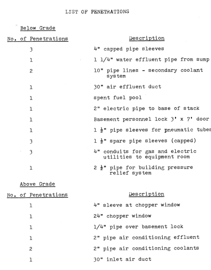
might be broken during an earthquake due to potential differ-ential seismic motions. This problem is particularly acute for below grade penetrations because of lack of freedom of motion of buried pipes. A list of all reactor building
pene-trations is found in Table 3.2.
The spent fuel pool is entirely below ground water level and breach of the tank would cause leakage of ground water
into the spent fuel. It thus appears unlikely that the spent fuel pool would become a radiation hazard before the tank could be repaired.
Special building penetrations for experimental facilities, such as the liquid helium production system and the pneumatic tube sample transfer system, are made in a manner to prevent any radioactivity release. These penetrations can be sealed
by automatic isolation valves and by manual operational
valves that can be closed from outside the reactor penetrations
(Sl).
The emergency core spray is to be supplied by two re-dundant systems connected to city water, The connection to
Table 3.2 LIST OF PENETRATIONS Below Grade No. of Penetrations
3
1 2 33
1 Above Grade No. of Penetrations 1 1 Description4" capped pipe sleeves
1 1/4" water effluent pipe from sump 10" pipe lines - secondary coolant
system
30" air effluent duct spent fuel pool
2" electric pipe to base of stack
Basement personnel lock 3' x 7' door
1 " pipe sleeves for pneumatic tubes
1
4"
spare pipe sleeves (capped)4" conduits for gas and electric utilities to equipment room
2 " pipe for building pressure relief system
Description
4" sleeve at chopper window
24" chopper window
1/4" pipe over basement lock
2" pipe air conditioning effluent 2" pipe air conditioning coolants
Table 3.2 (Continued) 1 2 2 Electric Service No. of Penetrations
3
23
1" cold water supply
2" pressure test lines 1" pressure test line 10" vacuum breaker lines
1" pipe 2" pipe
gaseous helium lines
3" pipe 4" pipe
3" conduit power wiring
1" conduit
2" C
2 " C 4" pipe
1 i" C for telephone
to allow for relative building motions.
If the pipes leading to the waste storage tanks (or the tanks themselves) are damaged by an earthquake, there is a potential leak of radioactive material into the groundwater. It is not intended that the waste storage tanks will be used for highly active waste (Sl). In the past twelve years, the sampling prior to discharge has shown that the solutions
dis-charged from the waste tanks has not required extra in-tank dilution prior to discharge into the sewer system with final
ocean discharge. Accidental release of this material into
the ground water is not predicted to create an off-site concentration above permissible limits in occupied areas.
Although rupturing of any rigid reactor building pene-tration due to potential differential earthquake motions will not simultaneously cause a major release of activity, the broken penetrations might cause a possible breach in the reactor containment. If an internal D20 pipe were to be
broken at the same time as the breach in the containment, there would be a potential release of tritium by evaporation. Calculations have been made in the MITR-II Safety Analysis Report (Sl) which indicate that in the event of a rupture
of both the D20 system and the containment system, the
off-site exposure to tritium activity would remain below per-missible yearly averaged limits for at least two days. Thus,
appropriate action.
3.6 SEISMIC INSTRUMENTATION
For a 14-day period from April 1, 1971 to April 14, 1971, a Schaevitz 1 g accelerometer was attached to the reactor
building to measure expected everyday building accelerations. The accelerometer was attached to the reactor building shield wall nearest the reactor stack at a position about two feet
above the reactor floor level. The electronics of the accel-erometer setup used are shown in Figure
3.7
and the accelero-meter was calibrated using the force of gravity. Theaccelerometer was oriented for five days in an approximate north-south direction (normal to the wall) and for five days in an east-west direction (parallel to the wall). For the remaining four days, the accelerometer was used to measure a vertical component of the acceleration.
The MITR-II site is located in an industrialized section of Cambridge, Massachusetts. The site is also adjacent to a railroad right of way. Numerous ground motions result from passing trucks and trains. The accelerometer measured a peak acceleration of these motions and not their frequency. The plot of peak accelerations was less erratic during weekends
when the reactor was shut down.
The peak acceleration measured during the 14-day period occured when the accelerometer was aligned parallel to the shield wall and a train passed on the tracks adjacent to the