Brain Microelectrode Array Systems
by
Timothy Andrew Fofonoff B.S., Engineering Physics (2000)
B.S., Computer Science (2000) University of Saskatchewan
SUBMITTED TO THE DEPARTMENT OF MECHANICAL ENGINEERING IN
PARTIAL FULFILLMENT OF THE REQUIREMENTS FOR THE DEGREE OF MASTER OF SCIENCE IN MECHANICAL ENGINEERING
AT THE
MASSACHUSETTS INSTITUTE OF TECHNOLOGY
FEBRUARY 2003
9 2003 Massachusetts Institute of Technology All rights reserved
Signature of Author:...
Department of Mechanical Engineering ., a 7 January 17, 2003 C ertified b y :... ... ...
Ian W. Hunter Hatsopoulos Professor of Mechanical Engineering and Professor of BioEngineering
, s Supervisor
A ccepted by:...
Am A. Sonin Professor of Mechanical Engineering Chairman, Department Committee on Graduate Students
MASSACHUSETTS INSTITUTE OF TECHNOLOGY
JUL 0 8 2003
Brain Microelectrode Array Systems
byTIMOTHY ANDREW FOFONOFF
Submitted to the Department of Mechanical Engineering on January 17, 2003 in Partial Fulfillment of the Requirements for
the Degree of Master of Science in Mechanical Engineering
Abstract
New methods for manufacturing microelectrode array assemblies, passive devices designed for intracortically recording brain activity in nonhuman primates, were developed and explored. Wire electrical discharge machining (EDM), chemical etching, micromilling, parylene deposition, and laser ablation were some of the processes employed to create distinctive microstructures with fine features and high aspect ratios. These microstructures, constructed from a variety of metals and polymers, were assembled to form the mechanical front end of a brain-machine interface (BMI).
The developed techniques were used to produce microelectrode array assemblies for the Telemetric Electrode Array System (TEAS), a surgically implantable wireless device to be used for motor cortex studies in nonhuman primates. Two prototypes of the TEAS microelectrode array assemblies were implanted in animals in order to validate the design and the manufacturing processes. Neural activity was successfully recorded. Future work is required in order to refine and further automate the processes. Similar devices could one day develop into neural prostheses for clinical use by outputting motor intent captured from brain activity in paralyzed patients.
Thesis Supervisor: Ian W. Hunter
Acknowledgments
I would first like to thank Sylvain Martel, my mentor and good friend, for initiating and
driving the TEAS project, and for inviting me to take part. I also give many thanks to Professor Ian Hunter for giving me the opportunity to work in the exciting MIT Biolnstrumentation lab.
I would like to acknowledge the other members of the TEAS team, Johann Burgert and
Jan Malisek for all their help and collaboration; Bobby Dyer and Colette Wiseman for their initial design and fabrication testing; Marie-Maude de Denus Baillangeon for helping me build the first prototype; and Thor Bjamason, Martin Labrecque, and Fedor Danilenko for their contributions.
I would like to thank our neuroscience collaborators, Nicho Hatsopoulos, John
Donoghue, Matthew Fellows, and Misha Serruya at Brown University for their input and for the opportunity to participate it the brain surgery that was performed there. And, I would like to especially thank Nicho, Naoum Issa, and Atul Mallik at the University of Chicago, for making the later surgeries in Chicago possible.
I thank Bobby Dyer, Bryan Crane, and Peter Madden for teaching me how to machine
and for always being willing to help me with mechanical engineering problems. I also thank the others in and around the lab, Ariel Herrmann, Patrick Anquetil, Robert David, Laura Proctor, Grant Kristofek, Rachel Zimet, Nate Vandesteeg, Mike Garcia-Webb, Andrew Taberner, Cathy Hogan, Lynette Jones, James Tangorra, Mealani Nakamura, Kate Melvin, John Madden, Wilson Chan, Aimee Angel, Michal Berris, Rachel Peters, Keng Hui Lim, Steve Buerger, and James Celestino, for helping to make this such a great place to work.
I also wish to thank all those close to me, some nearby and many now far away, who
have been there for me and with me over the years, and who have supported me when I've needed them most. Thank you guys!
And, most of all, I'd like to thank my parents, Dan and Ann Fofonoff, for all their loving support and understanding.
Table of Contents
Abstract ... 3
Acknow ledgm ents... 4
List of Figures... 8
List of Tables ... 12
Chapter 1: Introduction... 13
1.1 Brain-M achine Interfaces... 13
1.2 Intracortical R ecording ... 14
1.3 The Telemetric Electrode Array System (TEAS)... 15
Chapter 2: Brain Electrode System s ... 18
2.1 The Brain ... 18
2.2 The A ction Potential ... 19
2.3 Extracellular Recording ... 20
2.4 W ire Electrodes... 21
2.5 M icroelectrode Arrays ... 22
2.5.1 The U tah Arrays... 23
2.5.2 The M ichigan Arrays ... 24
Chapter 3: D esign Considerations ... 26
3.1 M odularity ... 26
3.2 Size and Shape ... 26
3.3 M aterial Properties... 28 3.3.1 Electrode M aterials ... 28 3.3.2 Insulating M aterials ... 29 3.3.3 Biocom patibility ... 29 3.3.4 Strength Considerations ... 30 3.3.5 V olum e Considerations... 33 3.4 Recording Considerations... 34
3.4.1 Electrode Surface M etals ... 34
3.4.2 Im pedance V alues... 35
3.5 D evice Im plantation... 37
Chapter 4: D esign and Fabrication ... 39
4.1 The TEA S Array D esign... 39
4.2 W ire Electrical D ischarge M achining... 42
4.3 Fabrication Process Overview ... 45
4.4 M icroelectrode Array Fabrication... 48
4.4.1 Planning and G enerating a Cutting Path... 50
4.4.2 Clam ping Considerations... 52
4.4.3 M achining Tim e Estim ates ... 57
4.4.4 Electrode M aterials ... 58
4.4.5 Chem ical Etching... 59
4.4.6 Electroplating... 62
4.4.7 Other Fabricated M icroelectrode Arrays ... 63
4.5 Insulating Substrate Fabrication ... 68
4.5.1 Substrate A lternatives ... 68
4.5.2 The TEA S Insulating Substrate ... 69
4.5.3 Other M anufacturing M ethods... 71
4.6 Electrical Insulation ... 71
4.6.1 Parylene D eposition... 72
4.6.2 Insulation Rem oval... 75
4.6.3 Laser Ablation... 76
4.7 Connector Cable Fabrication ... 79
4.7.1 The TEA S Connector Cable ... 79
4.7.2 Other Connector D esigns... 81
4.8 A ssem bly and Encapsulation... 81
4.8.1 Securing the Insulating Substrate... 82
4.8.2 An A lternative D esign ... 83
4.8.3 Electrical Connection... 84
4.8.4 Final Coatings ... 86
Chapter 5: Results... 87
5.2 Im plantation of the Prototypes... 93
5.2.1 Im plantation into a M onkey... 93
5.2.2 Implantation into M ice... 98
5.3 M echanical Results ... 101
5.4 N eural Recording Results ... 103
Chapter 6: Conclusion ... 106
Chapter 7: Future W ork ... 108
List of Figures
Figure 1-1. Images of a monkey skull showing the approximate areas available for the telemetric electrode array system (TEAS) [8,11]. (Photos: Jan Mali'sek)... 17 Figure 2-1. Diagram of the brain. (Illustration: The Society for Neuroscience [13])... 18 Figure 2-2. Diagram showing the shape of a typical intracellular action potential... 20 Figure 2-3. Plot of neural spikes intracortically recorded from the motor cortex of a
m onkey [8,11]. (Graph: Jan M alisek) ... 21 Figure 2-4. Image of the "Utah Array" (left) and connection options for an 11-electrode
assembly (upper right) and a 74-electrode assembly (lower right) manufactured for use in chronic recording. (Photos: Bionic Technologies, LLC [24], and
C yberkinetics, Inc. [25]) ... 23
Figure 2-5. Images of microelectrode arrays that were manufactured using silicon
micromachining. (Photos: University of Michigan, Ann Arbor [22])... 25 Figure 3-1. Drawing of an electrode subjected to an axial load upon insertion. ... 30 Figure 3-2. Drawing of an electrode subjected to a transverse force... 32
Figure 4-1. Image of the first prototype of the TEAS mechanical front end.
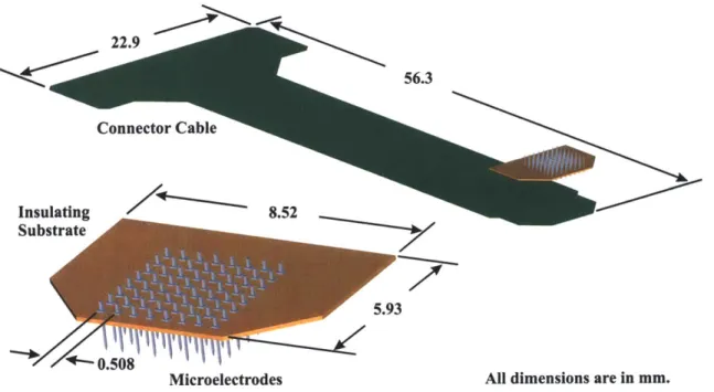
(Photo: R obert D yer)... 40 Figure 4-2. Schematic of the TEAS mechanical front end showing the major components.
... 4 1 Figure 4-3. Image the Charmilles Technologies wire electrical discharge machine
(w ire E D M )... 4 3 Figure 4-4. Drawing showing the wire EDM process. After the initial roughing cut,
several skim passes are normally performed in order to obtain the desired surface fin ish . ... 4 4 Figure 4-5. Image of an assembled TEAS microelectrode array assembly [11]. ... 45 Figure 4-6. Schematic showing the steps in the microelectrode array assembly fabrication
p ro cess... 4 7 Figure 4-7. Image of a microelectrode array still connected to its base. The array was
machined from a 9.5 mm diameter titanium rod. The electrodes are 1.7 mm in length and are spaced 508 ptm apart... 48
Figure 4-8. Schematic showing the dimensions of the TEAS microelectrode array... 49 Figure 4-9. Drawing of a typical cutting path used when wire electrical discharge
machining a microelectrode array. The wire starts at the crosshairs and loops in the direction of the arrow ... 52
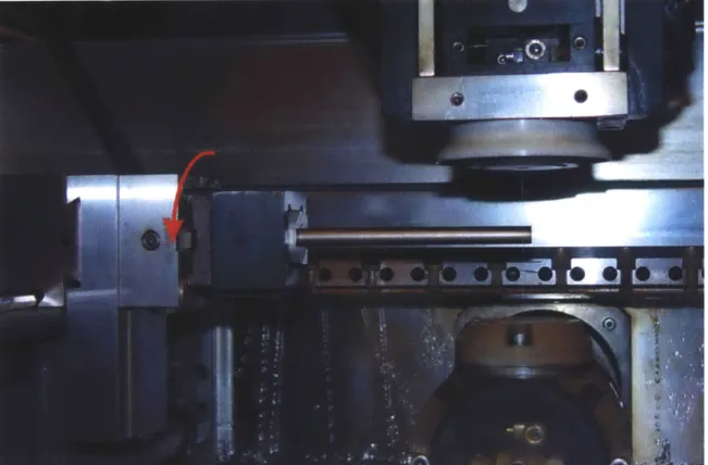
Figure 4-10. Image of a workpiece clamped and suspended in the tank of the wire EDM machine. The rotation of the workpiece that is done after the first cut is complete is show n by the arrow ... 53
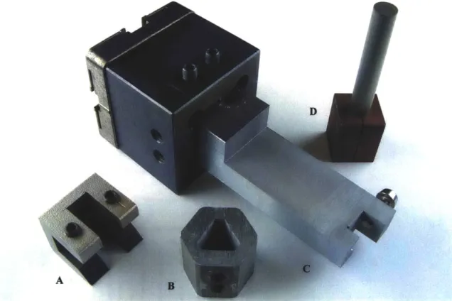
Figure 4-11. Image of several clamps used in the fabrication of microelectrode arrays by w ire E D M ... 54 Figure 4-12. Image of a microelectrode array clamped in order to prevent damage from
occurring when it is separated from the rod. When the wire cuts through the rod, the clam p will hold the array in place... 55
Figure 4-13. Image of a microelectrode array held in place with a specially-designed fixture just before being removed from its base by wire EDM. ... 56
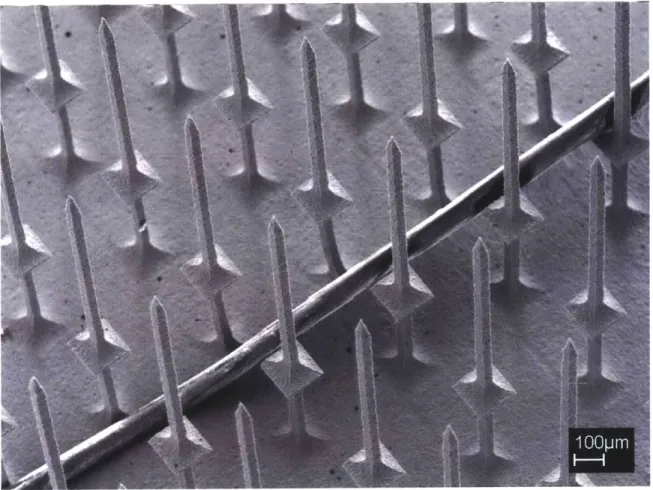
Figure 4-14. Magnified images of the microelectrode array, epoxied into the insulating substrate, just before being removed from its base by wire EDM... 57
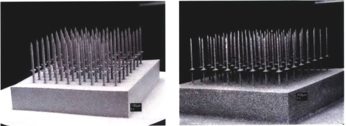
Figure 4-15. SEM images of a titanium microelectrode array before (left) [8,11] and after (right) it has undergone the chemical etching process... 60
Figure 4-16. SEM Image of a titanium microelectrode array with a human hair... 61 Figure 4-17. SEM images of titanium alloy microelectrode arrays before (left) and after
(right) they have been chemically etched and electroplated with gold... 62 Figure 4-18. Image of a microelectrode array with electrode lengths exceeding 5 mm... 63
Figure 4-19. SEM image of a microelectrode array that was machined to contain
electrodes of varying lengths [10]... 64 Figure 4-20. SEM Image of an 1141-electrode titanium alloy array that was machined in
a honeycom b pattern ... 65
Figure 4-21. SEM images of hexagonal microelectrodes after they have been
electroplated w ith gold... 66
Figure 4-22. Image of a fixture used when making honeycomb-patterned arrays. The fixture is capable of rotating the array 60 degrees with minimal misalignment and was manufactured from stainless steel by wire EDM... 66
Figure 4-23. Image of forty-nine 100-electrode arrays that were electrical discharge machined in parallel from a 100 mm diameter disk of titanium alloy... 67 Figure 4-24. Magnified images of the 100-electrode arrays that were machined in
parallel. The elevated sections are 5 mm square and the arrays' inter-electrode spacing is 500 p m . ... 67
Figure 4-25. Image of a microelectrode array epoxied into a polyimide substrate and held w ith forcep s... 70
Figure 4-26. Schematic showing the parylene coating process. ... 73
Figure 4-27. Image of the TEAS microelectrode array assembly fixed in place for the parylene deposition process. ... 75
Figure 4-28. SEM images of a parylene-coated assembly, consisting of platinum-coated electrodes epoxied into a polyimide substrate, after the electrode tips have
undergone laser ablation. ... 77
Figure 4-29. SEM image of a parylene-coated electrode that has had its tip laser ablated.
... 7 8
Figure 4-30. Image of the components of the TEAS prototype connector cable. They include a flexible PCB and an 80-pin connector [8,11]. (Photo: Jan Malisek)... 80 Figure 4-31. Image of a TEAS microelectrode array held in a fixture while the insulating
substrate is epoxied to the electrodes... 82
Figure 4-32. Image of a honeycomb-shaped tungsten carbide 1027-electrode array with a glass substrate mounted over the microelectrodes. The inter-electrode spacing is 2 5 0 p m ... 8 3
Figure 4-33. Images showing the shorter supports used to position the substrate while it is secu red . ... 84 Figure 4-34. Images of an array assembly held in a soldering fixture (left) and of the
solder junctions that join the electrodes to the connector cable (right). ... 84 Figure 5-1. Image of a typical plot from the impedance analyzer. The TEAS
microelectrode array was immersed in 0.9 % saline and a platinum reference
Figure 5-2. Graph showing the effect on the measured electrode impedance values from changing the number of laser pulses used when ablating parylene from the electrode tip s... 9 1
Figure 5-3. Graph showing the effect of changing the number of laser pulses used on the resulting electrode im pedances ... 92
Figure 5-4. Images of the percutaneous connectors (left) and the printed circuit board adapter made to connect the TEAS mechanical front end to the data acquisition system . (Photos: Robert D yer)... 94 Figure 5-5. Image of the monkey's skull and an exposed portion of its brain prior to the
im p lantation . ... 9 5
Figure 5-6. Image of the TEAS microelectrode array assembly cemented into place prior to in sertion . ... 9 6
Figure 5-7. Image of the microelectrode array moments before insertion with a pneumatic insertion tool [11]. (Photo: Jan M alasek)... 97
Figure 5-8. Image of the final acrylic encapsulating layer being applied [11].
(Photo: Jan M alisek)... 98
Figure 5-9. Images of the microelectrode array assembly mounted onto a
m icrom anipulator for implantation ... 99
Figure 5-10. Image of a microelectrode array above the mouse brain before implantation.
... 10 0
Figure 5-11. Image of the surgeons attempting to deform the connector cable to the shape of the brain [11]. (Photo: Jan M alisek)... 102 Figure 5-12. Plots of four neural spikes recorded from the cortex of a mouse... 104 Figure 5-13. Plots of four neural spikes that were recorded from the brain of a mouse
using the TEAS microelectrode array assembly... 105
List of Tables
Table 3-1. Material Properties of Some Possible Electrode Materials [26,27,28,29]. ... 28 Table 4-1: Example wire EDM cutting durations for a titanium alloy microelectrode array cut from a 10 m m diam eter rod... 57
Chapter 1: Introduction
Recent advances in neurophysiology and neuroscience in general are driving the prospects of the brain-machine interface (BMI). Alongside these advances are those in the areas of microfabrication and the development of microelectromechanical systems
(MEMS). Neuroscience has quickly become an area where such systems are common.
Implants in mammals serve as scientific tools and may soon develop into medical devices for human application [1,2,3,4].
Some brain-related devices are already in medical use. Deep brain stimulator implants, such as are used in therapy to relieve the effects of Parkinson's disease, are currently implanted and inject signals into the brains of patients in order to influence brain activity. Auditory prostheses, which stimulate the periphery auditory nervous system in order to restore some sense of hearing, are currently approved for human use and have been implanted in thousands of deaf patients of all ages [1].
Certain neuroscience studies have centered on establishing a link between the brain and the outside world. In particular, the cerebral cortex is an area where a lot of this work has focused. It is widely accepted that this area provides the easiest access to motor intent and sensory perception [2], and it is this region where potential future devices for restoring lost neurological functions associated with degenerative muscular diseases, stroke, or spinal cord injury would be interfaced.
1.1 Brain-Machine Interfaces
Progress towards creating brain-machine interfaces (BMIs) for use in humans is quickly accelerating [2]. The potential quality of life improvements that would be possible by developing an input BMI such as visual prosthesis that would allow a blind patient to see, or an output BMI that would allow a paralyzed patient to move, are immense. Even simpler devices that would allow a patient to move a cursor on a screen, or to possibly move a robotic arm, would make a significant impact. Although devices that do both output and input, allowing the user to additionally regain some position
feedback and possibly even some sense of touch, are a number of years away, simpler unidirectional devices will be emerging in the near future.
In addition to grouping BMIs by whether they input or output signals to the cortex, BMIs can be categorized into indirect BMIs and direct BMIs. An indirect BMI measures signals from outside the cortex. Several indirect BMIs use electroencephalogram (EEG) electrodes to noninvasively record electrical signals. Scalp recordings detect the synchronized activity of large numbers of neurons [5]. These signals are known as field potentials. Individuals have been trained to modulate these signals, which occur on the scale of a few seconds. The quality of EEG recordings can be improved by placing the electrodes beneath the skull and above the dura mater, the layer of tissue that covers the brain. Indirect BMIs can provide an interface for paralyzed victims, but it normally requires several seconds for a single action to be taken [2]. This is due to the inherent length of the signals and the indirect manner in which one modifies them. The use of such a BMI requires one's full attention. It is not possible for the BMI to record one's intended action or movement. For more resolution, one must use a direct BMI, which, in nonhuman primates, has been shown to predict intended movement by capturing the action potentials of many individual neurons from within the cortex [4].
1.2 Intracortical Recording
Direct BMIs are intracortical devices intended to record groups of individual neural signals, or spikes. These intracortical recording devices tend to be quite complex, both electrically and mechanically. Because the neural signals are normally 1 ms to 2 ms in duration and are about 100 pV in peak-to-peak, significant electronics are required in order to amplify, digitize, and possibly record the signals. If a prosthesis were to be controlled, a real-time processor would also be needed in order to sort the signals from noise and to interpret the captured information in a reasonable amount of time.
Although not yet ready for use in humans, intracortical recording devices are routinely used to conduct neuroscience research in monkeys. Mechanically, the devices must gather signals from a number of recording sites, typically arranged in a grid pattern. This structure is often referred to as a microelectrode array, and the larger mechanical
front end is often referred to as a microelectrode array assembly. Miniaturization is required in order to reduce the trauma that occurs upon insertion of the array into the brain and to ensure that the assembly can fit inside the limited volume available.
If a device is to be implanted long-term, biocompatibility becomes a primary
concern. The electronics of the system can reside either inside or outside the body. From a medical point of view, it is highly desirable to have the entire device implanted, with no elements penetrating through the skin. If the electronics are placed outside, which is the current norm, the percutaneous connector where the signals leave the head via cables requires special attention because it promotes an increased chance of infection at that location. From an electrical point of view, the use of cables has sometimes been problematic with recording performed in monkeys [6]. The cable's length increases the likelihood that electrical interference will be observed; artifacts are created when the cable is moved; and the monkeys sometimes have a tendency to abuse the cable. It was the desire to circumvent the problems encountered with the current cabled systems that lead to the development of the Telemetric Electrode Array System (TEAS).
1.3 The Telemetric Electrode Array System (TEAS)
The goal of the Telemetric Electrode Array System (TEAS) [7,8,9,10,11,6] was to create new hardware and to fabricate prototypes of the mechanical and electrical components of a wireless, brain-controlled prosthetic device. Designed for motor cortex studies in Macaca mulatta monkeys, the TEAS amplifies and digitizes action potentials and uses peak detection to extract the information-carrying features of the microvolt neural signals. The gathered information is then outputted through the skin by a wireless communication system. These functions are all performed by electronic systems that are implanted into the body, with no wires leaving the body. Because the neural signals are digitized in the body, there is less signal attenuation due to the shortening of the interconnecting wires, and the signal integrity is improved by the elimination of noise and artifacts previously caused by the movement of the connector cable [9]. An aim of the project was to eliminate the need for percutaneous connectors and cables. In addition to reducing the probability of infection by removing the connector site, freedom of
movement would be gained by the removal of the tethers that are presently required during recording. For a human subject, this would represent an appreciable quality of life improvement.
The TEAS places inside the body only the functionality absolutely necessary to record and transfer the desired signal timings and waveforms. By allowing the device to be reprogrammable and modular, software and functionality can be upgraded easily and without additional surgery or further risk to the subject. Much of the required computation is done outside of the body, where power and heating requirements are far less restrictive.
There are several components to the TEAS design: the mechanical front end, consisting of a microelectrode array assembly that is inserted into the brain in order to record neural activity; the analog electronics section, responsible for filtering, conditioning, and amplifying the recorded signals; the digital section that digitizes and buffers the amplified signals; the wireless unit that sends chosen information to an off-board computer; and the power section, comprised of batteries and a recharging unit. With the exception of the power section, which is situated in the abdomen of the monkey, where there is more room, the other components are designed to be implanted on the head of the animal. Figure 1-1 shows an image with highlighted areas reserved for the microelectrode array and the electronics section. Note that although the microelectrode array is implanted into the brain, the electronics are placed between the skull and the skin of the animal.
Aray Area
Electronics
10 mm
Figure 1-1. Images of a monkey skull showing the approximate areas available for the telemetric electrode array system (TEAS) [8,11]. (Photos: Jan Malisek)
The TEAS design incorporates commercial off the shelf (COTS) components whenever possible in order to decrease development time and complexity. A Bluetooth-based radio link is used to transfer the information in real time, and recharging of lithium polymer batteries through skin allows the system to be completely implanted. Although the COTS parts are state of the art and optimized for low-power operation and performance [7,8], the design of custom chips might result in significant space savings.
For the TEAS, the use of computer-controlled manufacturing techniques was also emphasized in an attempt to reduce development, revision, and fabrication time. An effort was made to keep as many design steps as possible under the control of the TEAS team members. This was especially true in the development of the mechanical front end.
All machining, whether by wire electrical discharge machining (EDM), by micro mill, or by excimer laser, and all encapsulating, whether by soldering, by electroplating, by
epoxying, or by depositing parylene, were done in the laboratory.
Chapter 2: Brain Electrode Systems
2.1 The Brain
A diagram of the brain is shown in Figure 2-1. The primary motor cortex (Ml) is
the area of interest for the telemetric electrode array system (TEAS) project. The TEAS device was designed to aid in the study of the interactions among groups of neurons and the information they convey about motor behavior [12].
Motor cortex
Frontal lobe
arletal lobe
ecipital lobe
Temporal lobe
Figure 2-1. Diagram of the brain. (Illustration: The Society for Neuroscience [131)
The neurons in the motor cortex have cell bodies that typically vary between 20 pm and 40 gm in size [5] and are spaced 40 pm to 60 pm apart [14]. The thin tube-like structures that extend from the neurons, called neurites, can extend for over 100 pm, however. These branch-like neurites can be divided into types: the dendrites, which function as the antennae of the neurons, and the axons, which serve to relay information through synapses at their ends.
Upon receiving input signals from other parts of the brain, the neurons in Ml have been found to relay those signals through synaptic transmission from one neuron to another, progressing through the central nervous system (CNS) in order to drive a group of muscles toward a desired goal. Bursts of neuronal activity, observed as neural spikes that occur in quick succession are observed immediately before and during movement
[15]. It is believed that this brain activity encodes the force and direction of voluntary
movement. In patients that have become paralyzed, it is often the case that though one cannot move a limb, for example, typical Ml activity still occurs. The signals are interrupted somewhere along the path from the MI region to the destined muscle group. It is the activity in the Ml region, in the form of individual neural spikes or action potentials, which is the focus of the TEAS.
2.2
The Action Potential
At rest, the inside of a neuronal cell body is at a potential difference of about
-65 mV with respect to the surrounding extracellular fluid and tissue [15]. This potential
difference between the interior and exterior of the cell is maintained by the expenditure of metabolic energy by the cell and results in an ionic gradient across the membrane of the cell. The cell membrane serves as a semipermeable barrier which allows certain substance and ions to flow in and out of the cell. When a neuron responds to a stimulus, the membrane potential depolarizes, reverse polarizes, and repolarizes by means of a rapid ion exchange [16]. This rapid change of the potential across the membrane potential is known as an action potential. A typical neuronal action potential is about
100 mV in amplitude and lasts about 2 ms. Figure 2-2 shows a diagram of a typical
+35 mV
--- ---... M --- 0 mV
-65 mV
I
I
2 ms
Figure 2-2. Diagram showing the shape of a typical intracellular action potential.
The voltage potentials of the signal presented in Figure 2-2 are those typically present inside the cell body, when measured with respect to the reference potential of the intercellular medium that surrounds the neuron. This waveform is similar to what one would expect from an intracellular recording in which an electrode is made to penetrate through the cell wall of a neuron. When electrodes are placed into cortex, however, they do not typically penetrate the neurons and therefore are used to make extracellular recordings.
2.3 Extracellular Recording
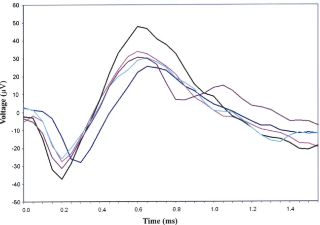
Since the fluids and tissues that surround neurons are electrically conducting, current flows in the environment surrounding the neuron when it undergoes the depolarizing-repolarizing effect of the action potential [16]. When electrodes are placed into the cortex of the brain in order to record neural spikes, the electrodes typically measure voltage fluctuations that occur outside of the cell bodies. The observed waveforms are on the same time scale as the intracellular action potentials, but are much lower in amplitude; extracellular recordings normally yield peak-to-peak amplitudes of up to 100 pV. Figure 2-3 shows neural spikes that were intracortically recorded from a monkey using a tethered data acquisition system [8,11].
60 s0 40 30 20 10 -10- -20--30 -40 -50 0.0 0.2 0.4 0.6 0.8 1.0 1.2 1.4 Time (ms)
Figure 2-3. Plot of neural spikes intracortically recorded from the motor cortex of a monkey [8,111. (Graph: Jan Maligek)
2.4 Wire Electrodes
One of the first and simplest techniques employed for the extracellular recording of neural spikes was the use of individual wire electrodes [17,1]. These electrodes are most easily created by simply cutting an insulated wire so that a cross-sectional surface is created at the end of the wire, although some sharpened tips have been obtained using etching techniques [17]. The exposed surface areas serve as the recording sites and the back ends of the wires are connected directly to a data acquisition system. Wires composed of platinum, stainless steel, or tungsten, for example, with diameters ranging from 13 pm to more than 80 gm, have been used to make chronic recordings of neural activity. Common materials used for insulation include silicon nitride, polyimide, Teflon
[18], and parylene. When smaller-diameter microwires are used, larger-diameter probes
can be used to reinforce the wires while they are being implanted. One or more microwires can be temporarily attached to a 150 pm diameter tungsten needle, for
example, using sucrose, dextrose, or a wax. The needle reinforces the microwires while they are inserted, and then is withdrawn after the binding agent dissolves in the body.
Both for scientific study and in the development of neural prostheses, there has been a desire for more electrodes to be used concurrently. As the number of signals recorded simultaneously was progressively increased, the use of individually inserted wire electrodes became increasingly difficult. It was this challenge that led to the development of the microelectrode array.
2.5
Microelectrode Arrays
Microelectrode arrays allow one to capture neural signals from a collection of recording sites with a known spatial distribution. A state of the art microelectrode array typically consists of a flat substrate out of which extend 25 to 100 parallel 1 mm long probes, or electrodes, which typically have diameters of about 80 pim and are evenly spaced at about 500 pm. The region of interest when making intracortical recordings is typically at a depth of about 1 mm below the surface of the brain, and some exposed, conductive part of each of these electrodes is used for the recording neural signals at this depth. The size of the recording site is carefully chosen in order to obtain a desirable electrical impedance value. Individual electrical paths must be made for each of the recorded signals to reach the front-end electronics with as little signal degradation as possible. These signal paths must be electrically isolated from each other and the entire array assembly must be insulated from all other brain activity.
The recording sites must be structurally supported during implantation. An assembly structure is required to connect the microelectrode array to additional cabling or to implanted electronics. When chronic recordings are made, a percutaneous connector is typically used as the exit point from the body. Biocompatibility is also especially important in long-term implants.
Many microelectrode array designs have been created over the past few years using a variety of techniques [1,2,17,19]. Few of these techniques however, involve batch process, computer aided design (CAD), computer numerical control (CNC), or automation of any kind. They generally lack the precision and repeatability required to
produce multitudes of arrays with virtually identical characteristics. Typically, the fabrication of a single microelectrode array requires many hours of manual labor. Some automation and repeatability has been achieved, however. Two successful silicon-based approaches are a single-component design developed at the University of Utah [20,21] and a contrasting assembly technique undertaken at the University of Michigan [22,23].
2.5.1 The Utah Arrays
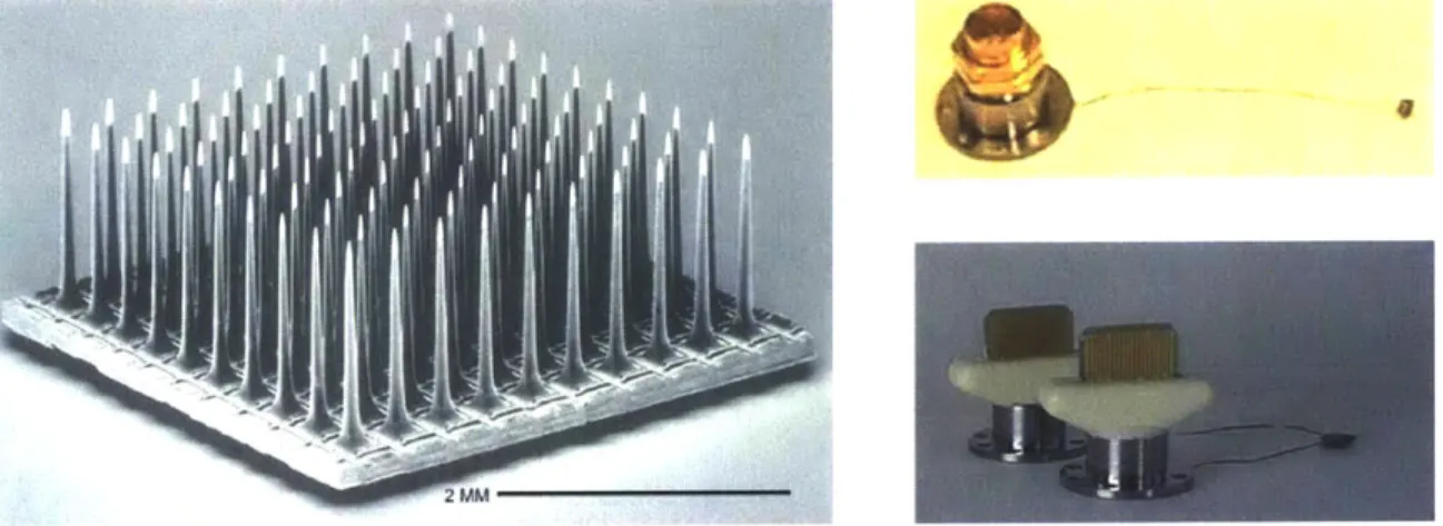
The microelectrode structures developed more that ten years ago at the University of Utah, commonly referred to now as "Utah Arrays" [20,21], consist of up to 100 pointed silicon electrodes projecting from a silicon substrate. The electrodes are isolated from one another by non-conducting glass and are typically 0.5 mm, 1.0 mm, or 1.5 mm in length with electrically-exposed tip regions of about 40 pm, when measured along the electrodes from their tips. These exposed areas correspond to electrode impedance values in the range of 50 kQ to 100 kO, when measured in 0.9 % saline with a reference electrode. The current form of this array is commercially available as the Bionic [24] array and is manufactured by Cyberkinetics, Inc. [25]. Figure 2-4 shows an image of the Bionic array and two connection options available for performing chronic recordings.
Figure 2-4. Image of the "Utah Array" (left) and connection options for an 11-electrode assembly (upper right) and a 74-electrode assembly (lower right) manufactured for use in chronic recording. (Photos: Bionic Technologies, LLC [24], and Cyberkinetics, Inc. [25])
The percutaneous connectors shown in Figure 2-4 (upper right) and (lower right) are secured on the outside of the animal's skull, and provide connectivity with 11 and 74 electrodes, respectively. Thin connector cables, consisting of several insulated individual
wires, link the connector to the microelectrode array, which is implanted into the brain beneath the dura mater.
This design and its manufacturing processes do have drawbacks. Foremost among them are the lack of flexibility in making minor alterations to the design and the number of manual processes used in constructing the devices. The processes used in
creating these devices are not computer numerically controlled (CNC), and the precision and repeatability of the characteristics of these arrays are only achieved through the diligence of practiced, highly-skilled technicians. The addition of features to these arrays, the modification of array configuration, and the use of alternate electrode materials are limited with this approach.
Bionic microelectrode arrays are widely regarded as having highly-desirable recording characteristics. They have been successfully implanted in many animals and historically deliver good recordings.
2.5.2 The Michigan Arrays
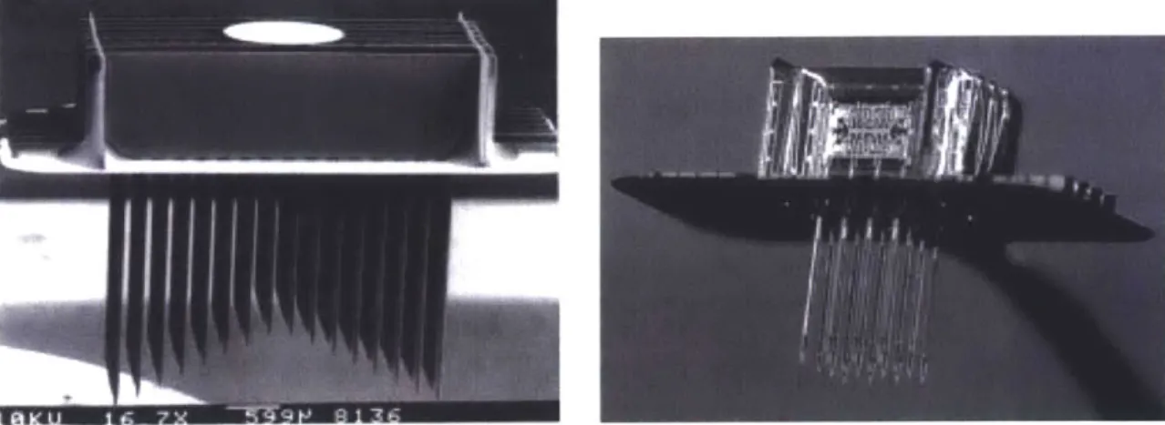
Microelectrode arrays recently manufactured at the University of Michigan, Ann Arbor, have been successfully fabricated using a silicon-wafer-based approach that combines silicon micromachining with complementary metal oxide semiconductor
(CMOS) fabrication processes [22,23]. Reactive ion etching (RIE), the evaporating of
metals onto surfaces, and the application of photoresists are all extensively used in the creation of these complex array structures. The fabrication of these microelectrode arrays requires many steps, but benefits from using a number of CNC processes. Additionally,
CMOS circuitry, such as preamplifiers, buffers, and multiplexers, has been successfully
integrated into the array structures. Examples of these array structures are shown in Figure 2-5.
Figure 2-5. Images of microelectrode arrays that were manufactured using silicon micromachining. (Photos: University of Michigan, Ann Arbor [22])
Although this approach represents a significant evolutionary step in the development of microelectrode arrays, it is not clear whether the integration of electronics with the microelectrode array structure itself is worth the loss in modularity and the overall increase in the complexity of the device and its fabrication. Though bringing the electrical front end as close to the array as possible is certainly advantageous, it might add flexibility and reduce complexity to create the CMOS circuitry as a separate module that can be attached to a mechanical front end chosen to suit a particular application. This would increase the versatility of the device and could also allow one to create electrodes from materials other than silicon.
Although these arrays have been widely used in recording field potentials, their ability to isolate neural signals from large populations of individual neurons has been limited [17].
Chapter 3: Design Considerations
There are many aspects to the design of microelectrode array assemblies. Several considerations must be weighed and the design details should be carefully chosen to match the intended application. The requirements for the TEAS device were largely determined by collaborating with neuroscientists who had a working knowledge of what had performed well in the past and of the type of environment in which the device would eventually reside. It was decided that an eight-by-eight array of 1 mm long electrodes with an inter-electrode spacing of about 500 gm was suitable for the first prototypes. These dimensions have been proven to work in practice and are very similar to those of the Bionic [24] arrays, commercially available from Cyberkinetics, Inc. [25], and they were seen as a good starting point.
3.1 Modularity
Using a configuration similar to one that is commercially available was seen as a way to increase the modularity of the design. A Bionic [24] array could be used in the place of the TEAS microelectrode array assembly in order to test the electronics if the need arose. And, conversely, the TEAS microelectrode array assembly could be connected to an existing data acquisition system in order to compare its characteristics and performance with those of the Bionic array.
Modularity is also highly desirable because it allows the TEAS to be more easily modified or tuned to suit specific applications. One can potentially use the same electronics modules with different arrays, or the array can be connected in a tethered configuration for acute experiments. This could also potentially allow portions of the system to be reused or replaced in subsequent implantations.
3.2 Size and Shape
What shape is best for microelectrodes is an issue often debated by neuroscientists. Sharp pointed tips are generally considered best, though blunt electrodes have been used extensively in the past [19]. The degree of taper given to the electrodes
and the shape of the electrode cross-section are additional variables that must be selected. Some argue that microelectrodes with round cross-sections are best. Others believe that electrodes with square cross-sections may more easily penetrate the brain. This could possibly reduce problems associated with the dimpling of the brain that is observed upon insertion of the device and the amount of trauma that is caused to the animal. It is thought, however, that the most pronounced contributing factors in the amount of trauma caused upon insertion of a microelectrode array are how the device is inserted and the volume that is occupied by the device in the brain [1]. By decreasing the cross-sectional areas of the electrodes, without reducing their length, one decreases the volume that the electrodes occupy in the brain. Ideally, the size of the electrode cross-sections should be determined based on the strength of the materials used in their manufacturing. There is a tradeoff, however, between the cross-sectional area of the electrodes and their strengths.
The overall structure of the mechanical front end can also take several forms. The electrodes must somehow be held in place at the chosen inter-electrode spacing, and electrical connectivity must be made between the electrodes and the front-end electronics. Recording sites with appropriate surface areas must be created and the remaining
electrode structure must be insulated.
If the microelectrode array is to be used in acute experiments only, then the
overall structure need not be as miniature, and it becomes advantageous to build bigger, more manageable connectors into the array.
3.3 Material Properties
3.3.1 Electrode Materials
Table 3-1 gives elastic moduli and strength characteristics for several materials that could be used in the fabrication of microelectrodes. It should be noted that many of the values in Table 3-1 can vary significantly depending on how the material was prepared by the supplier. The table does give values suitable for a rough comparison, however.
Table 3-1. Material Properties of Some Possible Electrode Materials [26,27,28,291.
Material Elastic Modulus (GPa) Strength (MPa)
Stainless Steel, ANSI Type 207 Tensile Yield: 205
316L, Annealed Ultimate Tensile: 515
Tensile Yield: 880 Titanium Alloy, 110 Compressive Yield: 970 Ti90-A16-V4, Annealed Ultimate Tensile: 950 Tensile Yield: 140 Titanium (100 %) 116 Ultimate Tensile: 220 Tungsten Carbide 680 Compressive Yield: 6250 Cemented in 10 % Cobalt
Gold (100 %) 80 Ultimate Tensile: 120
Platinum (99.95 %) 171 Ultimate Tensile: 140
Iridium (100 %), Annealed 524 Ultimate Tensile: 1000
3.3.2 Insulating Materials
Several alternatives exist for the materials used for insulating the array electrodes. These choices include silicon nitride, polyimide, Teflon [18], and parylene. Silicon nitride has historically been the most widely used material [17], but parylene is now generally perceived to deliver the best performance due to its inertness in the body and its being impervious to almost all substances. Additionally, its ability to be deposited in a uniform, pinhole-free conformal coating is very advantageous.
3.3.3 Biocompatibility
Biocompatibility is an important concern when chronic recording is to be done using microelectrode arrays. All of the materials involved in the fabrication of the assembly should be carefully chosen in order to minimize any harmful reactions in the body. If possible, this should include even the fully-encapsulated materials in order to protect against the unlikely event of the encapsulation being worn away. As BMIs are developed for clinical use, biocompatibility issues will become even more important.
When a microelectrode array system is designed and constructed to be used acutely, biocompatibility considerations can be altered accordingly. Using a microelectrode array assembly built for taking chronic recordings in an acute experiment would likely put unnecessary constraints on the design. For example, one is normally less concerned with biocompatibility issues if the device will not be left for a long time in the animal, and even less so if the animal is to be sacrificed immediately following the experiment. This is not to say that the materials should be chosen arbitrarily, but stronger, less biocompatible materials could be used in the underlying, encapsulated components of the device. Also, less costly approaches can be taken. This may be especially true in the design of the connection between the array and the data acquisition system. Acute experiments are normally performed with the cranium open, which allows for the possibility of using larger, simpler connectors in place of the specially-designed, more costly connectors typically used for chronic recordings.
3.3.4 Strength Considerations
If a large enough axial load is incident on the array's microelectrodes upon
insertion into the brain, for example, the electrodes are at risk of undergoing buckling and collapse. Bucking occurs when lateral bending is observed [30]. Under an increasing axial load, the lateral deflection of the electrode will increase as well, until the electrode undergoes inelastic yielding, or in the case of a brittle material, until the electrode fractures. An array of microelectrodes can be modeled as a collection of ideal elastic columns fixed in a substrate at one end and free at the other. Upon insertion, an electrode is subjected to an axial Euler load as shown in Figure 3-1.
P
Figure 3-1. Drawing of an electrode subjected to an axial load upon insertion.
The critical load for an ideal elastic column that undergoes Euler buckling is given by
)r2EI
Pe = 2 , (3-1)
Le
where Pcr is the critical load, E is the elastic modulus of the material, I is the moment of inertia of the column, and Le is the effective length of the column [30]. For a column fixed at the base and free at the top, the column deflects in a mode where the effective length is twice the length of the column. The effective length is therefore
Le = 2L , (3-2)
where L is the length of the electrode. Substituting Equation (3-2) into Equation (3-1) gives
P = 2 . (3-3)
"~ 4L 2
The moment of inertia for an electrode with a square cross-section is given by
4
I = W (3-4)
12
where w is the width of the electrode.
From Equations (3-3) and (3-4), one observes that the critical load, Pcr, depends only on the dimensions of the electrode and the elastic modulus of the material from which the electrode is made. For an electrode of given dimensions, the critical load is proportional to the elastic modulus value. When the axial load is less than Pr, the electrode remains stable and will return to its rest position after the load is removed. If the load is larger than Pcr, the electrode becomes unstable and the structure buckles.
Using the data from Table 3-1 and the above equations, one observes that silicon, titanium, and titanium alloy can all bear similar axial loads. Stainless steel 316L can bear about 85 % more axial load than silicon, however, and tungsten carbide can bear over
600 % more.
From Equations (3-3) and (3-4), one also observes that the critical axial load is proportional to the inverse of the square of the electrode's length and directly proportional to the electrode's width, raised to the fourth power. Put another way, if one doubles the length of an electrode, the axial load that it can bear is decreased by a factor of four, and if one decreases the width of an electrode by a factor of two, the axial load that the electrode can bear is decreased by a factor of sixteen. Again using the data from Table 3-1, one can calculate that by using tungsten carbide in the place of silicon or titanium, one can reduce the electrode widths by over 35 %, while still being able to bear similar axial loads.
When one refers to one array being stronger than another, one is often referring to the susceptibility of the arrays to damage while being positioned during the implantation procedure or while they are being connected to additional hardware. The maximum stress will occur in an electrode, for a given force, when the force is applied transversely at the electrode tip, as shown in Figure 3-2. This represents the least amount of force required in order to damage the electrode.
F
Figure 3-2. Drawing of an electrode subjected to a transverse force.
Because the electrode can be considered a long slender beam, and because the shear stresses are much smaller than the bending stresses due to the geometry, the maximum stress [31] is given by
Mc (5
UrM = ,C (3-5)
I
where M is the maximum bending moment, c is the distance from the neutral axis of the deflection to the edge of the electrode, and I is the moment of inertia of the column.
The maximum stress in the electrode occurs at the section with the greatest bending moment, which in this case is at the electrode's base. By balancing the moments on the electrode and substituting, Equation (3-5) becomes
OUmx = FLc (3-6)
I
where F is the transverse force and L is the length of the electrode. From Equation (3-6), one observes that the maximum stress is proportional to the transverse force that is applied to the electrode, as well as to the electrode's length. In order to ensure that electrodes will not collapse, all forces that are applied to the electrodes for whatever
reason should be kept at levels which ensure that the maximum resulting stresses remain significantly below the yield strength of the electrode material.
An important consideration when choosing a base material for a microelectrode array is whether it is desirable for the electrodes to be brittle or to be ductile. Electrodes made of silicon or tungsten carbide will tend to break off if exposed to high forces, while electrodes constructed from stainless steel or titanium will tend to bend. One should consider whether it is more advantageous to have an electrode break off or to have it bend and collapse when subjected to high loads. In fabrication and assembly, electrodes can be bent back into position. This can increase the yield of the manufacturing processes by reducing the likelihood of irreversible damage. Also, one may want to reduce the possibility of dislocated, detached electrodes retained in the brain. There is a tradeoff, however, as the use of a cemented composite like tungsten carbide introduces a considerable increase of strength to the electrodes, allowing them to bear greater loads.
3.3.5
Volume Considerations
In order for a neuroprosthesis to provide fine motor control, it is necessary to produce recording sites distributed at a high spatial density. By increasing the number of recording sites over a given area, one increases the likelihood of capturing the necessary neural signals. Unfortunately, in doing so, one tends also to increase the volume that is occupied by the array electrodes in the brain. Trauma to the brain is related to the volume of neural tissue that is displaced. It is therefore desirable to maximize the number of recording sites per volume of neural tissue displaced, the RS/NTD ratio [1].
Several approaches can be taken when manufacturing microelectrode arrays in order to increase the density of the recording sites. One approach is to simply decrease the inter-electrode spacing of the array. Without simultaneously decreasing the electrode widths and therefore increasing the RS/STD ratio, however, an increased volume of neural tissue will be displaced. By using stronger materials, one can reduce the electrode widths and increase the RS/NTD ratio without compromising electrode strength. This can potentially be used to avoid the increase in the volume of brain that would otherwise be displaced.
Another approach that can be taken is to alter the array pattern or configuration. Electrode arrays are typically manufactured in square or rectangular configurations. The use of alternative configurations is possible, however. For example, microelectrode arrays with hexagonal configurations resembling the shape of a honeycomb, with the electrodes equally spaced from their six closest neighboring electrodes, could be manufactured. This configuration increases the electrode spatial density of the array by over 15 % for a given inter-electrode spacing when compared with the common square configuration. Arrays with this configuration are displayed in Chapter 4.
Yet another approach that can be taken is to distribute the recording sites over a range of depths. This can be accomplished by fabricating arrays of electrodes with varying lengths, as demonstrated in Chapter 4. In addition, on could also potentially fabricate microelectrode arrays with more than one recording site on each electrode. The recording sites could, for example, be distributed over a range of depths along each electrode. Although this represents a challenging fabrication problem, it would dramatically increase the RS/NTD ratio, provided that the recording sites could be added to the electrodes without substantially increasing the electrode dimensions.
3.4 Recording Considerations
Whenever recording of bioelectric events is performed, one must pay special attention to the impedance values involved. These include the impedances of the analog front-end electronics, of the microelectrodes and the connecting wire, and of the junctions between the metal electrodes and the fluid of the brain. Carefully selecting these impedance values is especially important when making intercellular recordings in the cortex due to the small signals involved.
3.4.1 Electrode Surface Metals
When a metallic electrode is introduced into a biological environment or an aqueous solution, some of the metal ions will typically enter into solution and some the ions in the solution will typically combine with the electrode [19]. The net result of this reaction is that a charge potential appears at the electrode-electrolyte interface. This
charge potential at the electrode-electrolyte interface impedes to some degree the electrode's ability to pass charge and introduces capacitive effects. The resulting ionic distribution has been found to substantially affect an electrode's properties. It has been found that platinum, and more specifically a form of porous platinum known as platinum black, delivers very favorable electrode-electrolyte impedances. It is for this reason, and due to its excellent biocompatibility, that platinum is seen as the metal encapsulant of choice when fabricating microelectrode arrays.
3.4.2 Impedance Values
Because of the nature of the electrode-electrolyte interface at the recording sites, electrode impedance can be represented by an equivalent series combination of resistance and capacitance [19]. In microelectrodes, both resistance and capacitance typically vary approximately inversely with the square root of frequency. Additionally, the reactance,
X, of an electrode, which can be represented by
(3-7)
where
f
is the frequency and C is the series capacitance, is typically approximately equal to the electrode's resistance [19].An electrode's series capacitance, C, is known to vary with the surface area, a, of its recording site according to
C = Ka (3-8)
fa
where K is a constant that depends on the nature of the metal-electrolyte junction and a is a constant that describes the rate at which the capacitance decreases with increasing frequency. Typical values for the constants K and a are 1.608 F/M2 and 0.525 for
stainless steel and 117.59 F/m2 and 0.211 for platinum black, when measured in 0.9 % saline [19]. As can be seen from these K values, electrolytically-preparing the electrode, for example by the deposition of platinum black, can have a dramatic effect on the series
capacitance and impedance of the electrode. Roughened surfaces, increased electrolyte concentrations, and increased temperatures have all additionally been found to increase the values of the series-equivalent capacitance [19].
The constant a is typically about 0.5 and is related to the phase angle,
#,
by# = -(I - a).
(3-9)2
The phase angle,
#,
whose tangent is the ratio of reactance to resistance, is typically therefore about 45 degrees and is fairly constant over the most relevant frequency range of 100 Hz to 10 kHz [17]. The electrode impedance, Z, for the series-equivalent resistance, R, and reactance, X, is given byZ= R2 +X 2
. (3-10)
By assuming R = X, and by substituting Equations 3-7 and 3-8 into Equation 3-10, the
impedance becomes
Z =V-X= - 7_Ia Ka (3-11)
A suitable range for the electrode impedances is believed to be 50 ku to 150 ka
at 1 kHz when measured using a reference electrode after immersing the array in 0.9 % saline [17]. This range of values is consistent with those experimentally measured on a Bionic [24] microelectrode array system known to give satisfactory results. Using values of 0.366 and 49.5 F/M2 for constants a and K, corresponding to a medium platinum
black finish, an electrode recording site area of 570 m2 is required in order to produce
an impedance of 100 kQ at 1 kHz. Assuming a hemispherical electrode tip with a 10 Am radius, which is a fair approximation, this surface area leads to a recording site diameter of about 20 pm when viewed from above the electrode tip.
Tradeoffs are involved when selecting the electrode impedances. One is the tradeoff between good signal recording and the likelihood of recording any signal at all.
of recording from a nearby neuron. But at the same time, one increases the likelihood of recording from more than one neuron, and one will likely also record an increased amount of noise. The neural spike could potentially get washed out. If one were to select a higher impedance value, the quality of the potential neural recording is increased. However, with a higher impedance value, the recording site would have to be closer to the neuron in order to register a signal at all.
The impedance should additionally be kept well below the input impedance of the front-end electronics in order to minimize loading errors and other potential problems. The impedance values chosen for the electrodes must be compatible with the input impedances of the first-stage operational amplifiers (op-amps) of the analog front end. If the input impedance of the analog front end is too low, significant loading errors can occur. Charging of the electrodes can result from the bias currents of the op-amps, creating undesirable DC offset errors, if no bias return path is provided.
Creating electrodes with chosen impedance values is not a simple task. Whatever method is used to produce exposed surface areas on the electrode tips will require considerable calibration. In addition to the area that is exposed, the resulting impedance will be a function of the surface metal, including its porosity and its uniformity.
3.4.3 Grounding and Reference Paths
A ground or reference electrode is required in order to make the recordings. A
low-impedance return path is preferred in order to ensure that the observed signal is derived from the intended electrode and is not a result of the presence of noise on the reference electrode. An insulated wire, with a 1 mm to 2 mm recording site is normally used for this lower-impedance electrode. Other options for this reference path include the use of a microelectrode on the array with a recording site of increased area and the use of several electrodes connected in parallel.
3.5
Device Implantation
How a microelectrode array will be implanted is an important consideration for its design. Insertion of the array can be done using a variety of tools and at a variety of
speeds. For example, the array can be inserted slowly using a micromanipulator or an electric micrometer drive. Some dimpling of the brain is often observed when the array is inserted slowly, however. This effect becomes more pronounced as the density of the array is increased. It has been demonstrated that by generating a controlled impulse on that back side of the array, it can be propelled into the brain with minimal dimpling. The Bionic [24] pneumatic inserter, manufactured by Cyberkinetics, Inc. [25], is a device that has been designed to serve this purpose.
Chapter 4: Design and Fabrication
A microelectrode array assembly consists of several components, all of which
present fabrication challenges. When designing a device at this scale, one must at once consider how each component will be built and how all of the components will be assembled. Often, special tools and fixtures must be constructed in order to aid in handling and in order to ensure the proper alignment of the components.
Microelectrode array assemblies can take a large variety of forms, and there are numerous manufacturing technologies and methods that could be used in their fabrication. The methods that were developed in order to construct the TEAS mechanical front end and the other microelectrode arrays shown here were derived from expertise and technologies available at the Massachusetts Institute of Technology's Biolnstrumentation Laboratory. Specifically, the use of wire electrical discharge machining (EDM), printed circuit board rapid-prototyping equipment, and parylene deposition equipment were instrumental in the creation of these arrays.
4.1 The TEAS Array Design
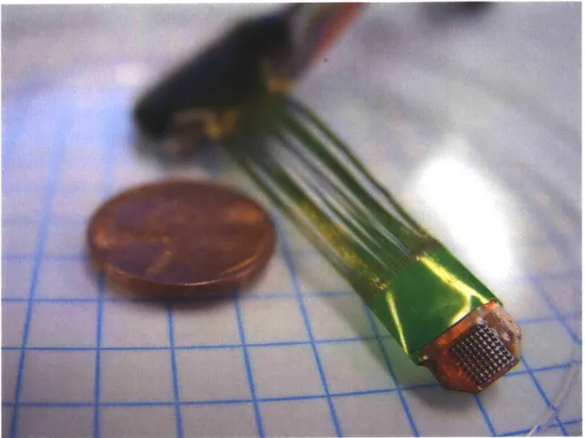
The first two prototypes of the mechanical front end fabricated for the TEAS project were designed to be implanted into the motor cortex of a Macaca mulatta monkey. The region of interest for the intended recording is at a depth of 1 mm below the surface of the brain. The design of the first prototypes is most similar to that of the Bionic [24] microelectrode array assemblies manufactured by Cyberkinetics, Inc. [25]. As highlighted in Section 2.5.1, this type of assembly, commonly known as the Utah array [20,21], is normally used for intracortical recording and consists of an evenly-spaced, square array of silicon electrodes that are normally made to penetrate about 1 mm below the surface of the brain. This type of array assembly has delivered satisfactory results and its specifications were seen as a good starting point for the TEAS design. Figure 4-1 shows an image of the first prototype of the TEAS mechanical front end. This microelectrode array assembly was implanted into the motor cortex of a monkey.
![Figure 1-1. Images of a monkey skull showing the approximate areas available for the telemetric electrode array system (TEAS) [8,11]](https://thumb-eu.123doks.com/thumbv2/123doknet/14182610.476568/17.918.156.760.172.459/figure-images-monkey-showing-approximate-available-telemetric-electrode.webp)