In Situ Deprotection of Polymeric Binders for
Solution-Processible Sulfide-Based All-Solid-State Batteries
Jieun Lee, Kyulin Lee, Taegeun Lee, Hyuntae Kim, Kyungsu Kim, Woosuk Cho,
Ali Coskun, Kookheon Char,* and Jang Wook Choi*
J. Lee, Dr. K. Lee, T. Lee, H. Kim, Prof. K. Char, Prof. J. W. Choi
School of Chemical and Biological Engineering and Institute of Chemical Processes
Seoul National University
1 Gwanak-ro, Gwanak-gu, Seoul 08826, Republic of Korea E-mail: [email protected]; [email protected] Dr. K. Kim, Dr. W. Cho
Advanced Batteries Research Center Korea Electronics Technology Institute
25 Saenari-ro, Bundang-gu, Seongnam, Gyeonggi 13509, Republic of Korea Prof. A. Coskun
Department of Chemistry University of Fribourg
Chemin de Musee 9, Fribourg 1700, Switzerland
The ORCID identification number(s) for the author(s) of this article can be found under https://doi.org/10.1002/adma.202001702.
from the electrolyte would allow the safety issue to be fundamentally dismissed. Furthermore, ASSBs offer additional advantages, such as enhanced interfacial stability with Li metal electrodes and the bipolar stacking of electrodes for higher energy density.[3] Based on this motiva-tion, various inorganic solid electrolytes (SEs) have been identified in the past decades. Among several different classes, sulfide-based SEs, including Li7P3S11,[2a] Li10GeP2S12,[4] and Li9.54Si1.74P1.44S11.7Cl0.3,[5] are remarkable because some of them realize high ionic conductivity of the order of 10−2 S cm−1, which is even comparable to those of their liquid counterparts. In particular, the argyrodites Li6PS5X (X = Cl, Br, and I) are of great interest by virtue of their competitive ionic conductivity at room temperature, mechanical proper-ties that allow intimate particle-to-particle contact, ease of synthesis, and the afford-ability of their raw materials.[6] Despite the advantages associated with the inherent properties of these materials, ASSB tech-nology continues to lag at the research stage because a large-scale manufacturing scheme has yet to be established. Thus far, ASSBs have been tested mainly by fabricating lab-scale pellet-type cells for which the electrode and electrolyte powder were pressed into an assembly of individual layers. Targeting large-scale production, solution-based roll-to-roll coating and drying are preferred from the perspectives of economic feasi-bility and mass productivity.[7] Indeed, the increasing demand for solution-based manufacturing processes for ASSBs has recently been recognized.[8] However, detailed conditions for slurry preparation and electrode fabrication are yet to be identi-fied and optimized.
A major challenge in developing solution-processed ASSBs based on sulfide SEs lies in the difficulty of finding the right combinations of polymeric binder and slurry solvent. Critically, most sulfide SEs are soluble in polar solvents, including the most popular solvent for LIB slurries, N-methyl-2-pyrrolidone (NMP).[9] Hence, solvent selection is limited to nonpolar or relatively less polar solvents. This restriction on the choice of solvent consequently limits the choice of binder, implying that most polymers with polar functional groups cannot be consid-ered.[10] More seriously, binders that are compatible with these solvents and sulfide SE pairs in terms of polarity would result
Sulfide-based all-solid-state batteries (ASSBs) have been featured as prom-ising alternatives to the current lithium-ion batteries (LIBs) mainly owing to their superior safety. Nevertheless, a solution-based scalable manufacturing scheme has not yet been established because of the incompatible polarity of the binder, solvent, and sulfide electrolyte during slurry preparation. This dilemma is overcome by subjecting the acrylate (co)polymeric binders to protection−deprotection chemistry. Protection by the tert-butyl group allows for homogeneous dispersion of the binder in the slurry based on a relatively less polar solvent, with subsequent heat-treatment during the drying process to cleave the tert-butyl group. This exposes the polar carboxylic acid groups, which are then able to engage in hydrogen bonding with the active cathode material, high-nickel layered oxide. Deprotection strengthens the electrode adhesion such that the strength equals that of commercial LIB electrodes, and the key electrochemical performance parameters are improved markedly in both half-cell and full-cell settings. The present study highlights the poten-tial of sulfide-based ASSBs for scalable manufacturing and also provides insights that protection−deprotection chemistry can generally be used for various battery cells that suffer from polarity incompatibility among multiple electrode components.
As the territory of lithium-ion batteries (LIBs) is expanding to the green transportation sector, concerns about LIBs pre-senting a fire hazard originating from the use of flammable carbonate solvents have been elevated.[1] All-solid-state batteries (ASSBs) are receiving considerable attention as viable alterna-tives to LIBs,[2] as the elimination of flammable liquid solvents
http://doc.rero.ch
Published in "Advanced Materials doi: 10.1002/adma.202001702, 2020"
which should be cited to refer to this work.
in weak adhesion to the current collector or weak cohesion between active materials as well as between the active materials and SEs. The inferior mechanical properties of the resulting electrodes would result in poor processability[10] and inferior electrochemical performance represented by high interfacial resistance, capacity fading upon cycling, etc., thereby placing a severe hurdle in the way of the entire sulfide-based ASSB technology.
Because of the dilemmatic issue of the need for compat-ibility among the three components (solvent, binder, and SE), only nonpolar or weakly polar solvents, such as para(p)-xylene, toluene, hexane, and anisole, have been adopted together with polymeric binders with low polarities, such as butadiene rubber (BR),[8b] styrene–butadiene rubber (SBR),[8c] styrene– ethylene–butylene–styrene rubber (SEBS),[8d] poly(vinyl chlo-ride) (PVC),[8e] nitrile butadiene rubber (NBR),[8g,11] silicone rubber,[8c] and ethyl cellulose.[8i,12] In order to overcome this challenging trade-off between the chemical compatibility and mechanical stability of the electrode, out-of-the-box approaches are a “must-need”.
Herein, we report a novel binder concept involving protec-tion−deprotection chemistry that can alter the polarity of the binder in the course of the electrode manufacturing process, that is, during the slurry mixing stage and final electrode fabrication stage. The polar functional groups of the binder
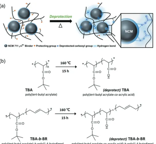
were protected by nonpolar tert-butyl (t-butyl) groups to ensure that the polymer is compatible with the argyrodite sulfide SE, Li6PS5Cl (abbreviated as LPSCl) in the slurry mixing pro-cess. This polymer could be deprotected by thermally cleaving the t-butyl group during the process of drying the electrode, thus enabling a polar binder to be obtained (Figure 1a). The resulting electrode exhibited superior electrode adhesion and electrochemical properties in various respects in comparison with those of its BR counterpart, a common reference binder for solution-processed sulfide-based ASSBs. Apart from the enhanced mechanical and electrochemical properties of the ASSB cells, the current investigation opens a new avenue in battery binder designs, that is, protection−deprotection chem-istries that allow the binder to transform its functionality at dif-ferent stages of the cell manufacturing process.
To realize polymeric binder design based on the novel concept of protection−deprotection chemistry, we chose poly(tert-butyl acrylate) (TBA) and its block copolymer version, poly(tert-butyl acrylate)-b-poly(1,4-butadiene) (TBA-b-BR), with the carboxylic acid functional groups of both protected by ther-mally cleavable t-butyl groups. The protection scheme involving the t-butyl group has been used in a wide range of synthetic pro-cedures in the polymer chemistry field because it allows certain functionalities or positions of a polymer to be protected while modifying others, thus offering “orthogonal” modification.[13]
Figure 1. a) Schematic illustration of the protection−deprotection chemistry for the adhesive interaction between the polymeric binder and active material in the composite cathode. b) Structural changes of poly(tert-butyl acrylate) (TBA) and poly(tert-butyl acrylate)-b-poly(1,4-butadiene) (TBA-b-BR) after thermal deprotection.
On the other hand, it is noted that TBA is commonly used as a precursor for the synthesis of the well-known poly(acrylic acid) (PAA).[14] Although PAA is a widely used binder for LIB electrodes,[15] it is not suitable for sulfide-based ASSBs because of the polarity mismatch; the relatively high polarity of PAA makes it soluble only in polar solvents, which are highly reac-tive with sulfide SEs. However, by protecting the carboxylic acid group with a t-butyl group, the polarity of PAA can be lowered, and the resulting lower polarity of TBA and TBA-b-BR renders them soluble in nonpolar or weakly polar solvents. Upon expo-sure to heat treatment, the t-butyl ester group is decomposed to release isobutene and consequently yield carboxylic acid,[16] as illustrated in Figure 1b. The deprotected polymers are denoted as butyl acrylate-co-acrylic acid) and poly(tert-butyl acrylate-co-acrylic acid)-b-poly(1,4-butadiene), abbreviated as (deprotect) TBA and (deprotect) TBA-b-BR, respectively. Ultimately, the original TBA and TBA-b-BR with moderate adhesion to the NCM active material are transformed into their PAA analogs with high adhesion while being processed using existing electrode fabrication steps. Thus, the overall polymer transformation occurs in situ. To the best of our knowledge, the present study is the first to employ in situ polarity switching of a polymeric binder for ASSB electrodes.
The weight loss of the TBA and TBA-b-BR binders was monitored by isothermal thermogravimetric analysis (ITGA) (Figure S1a,b, Supporting Information). When maintained at a constant temperature of 120 °C, no significant change in mass was observed, whereas the weight corresponding to the t-butyl group was lost after 15 h when the constant temperature was raised to 160 °C. This observation indicates the presence of a threshold temperature for deprotection of the t-butyl group. On the other hand, differential scanning calorimetry (DSC) profiles (Figure S1c,d, Supporting Information) reveal that the glass transition temperatures of TBA and TBA-b-BR are around 45 °C and below 30 °C, respectively, so that both binders are in the rubbery state at the deprotection temperature of 160 °C. The chemical bonds of TBA and TBA-b-BR (before deprotection) and (deprotect) TBA and (deprotect) TBA-b-BR (after deprotection) were investigated by Fourier transform infrared spectroscopy (FT-IR) in attenuated total reflectance (ATR) mode (Figure 2a and S2a, Supporting Information). Before the exposure to heat, TBA presented strong absorption bands for t-butyl at 1350 and 1400 cm−1 and the C=O stretching of the ester at 1730 cm−1. After thermolysis, the signature peaks of t-butyl at 1350 and 1400 cm−1 disappeared, and the characteristic ester stretching band at 1730 cm−1 broadened owing to the appearance of the car-boxylic acid band at 1709 cm−1 and anhydride bands at 1752 and 1804 cm−1.[17] Even when TBA was blended with the LPSCl SE, the deprotection occurred in a consistent manner (Figure S2b, Supporting Information), implying that the presence of the LPSCl SE did not perturb the deprotection reaction. When tested solely targeting binders, the TBA film exhibited far increased adhesion with the aluminum current collector after deprotection (Figure S3, Supporting Information).
In an attempt to evaluate the chemical compatibility of TBA, (deprotect) TBA, TBA-b-BR, and (deprotect) TBA-b-BR with argyrodite LPSCl SE, X-ray diffraction (XRD) and Raman analyses were conducted (Figure S4a−d, Supporting Informa-tion). In this test, the LPSCl electrolyte was immersed in the
TBA and TBA-b-BR binder solutions based on butyl butyrate for 24 h followed by drying at 120 or 160 °C. After this treatment, the characteristic[6b,18] peaks of the LPSCl remained on the XRD pattern (Figure S4a,c, Supporting Information), and the signa-ture peak indicative[18,19] of PS
43− (422 cm−1) was also unchanged on the Raman spectra (Figure S4b,d, Supporting Information). Hence, the LPSCl SE was concluded to be chemically compat-ible with all the binder solutions tested herein.
Upon thermal deprotection, the 180° peeling test indicates that the (deprotect) TBA and (deprotect) TBA-b-BR electrodes showed far stronger adhesion compared to that of their pro-tected versions and the bare BR electrode (Figure 2b). This test was carried out by preparing composite cathode electrodes containing 74.5 wt% of active material (LiNi0.7Co0.15Mn0.15O2, abbreviated as NCM711), 21.5 wt% of LPSCl, 2 wt% of super P,
Figure 2. a) Fourier transform infrared spectroscopy (FT-IR) (attenuated
total reflectance, ATR) spectra of the poly(tert-butyl acrylate)-b-poly(1,4-butadiene) (TBA-b-BR) and (deprotect) TBA-b-BR. b) 180° peeling test results of the electrodes containing (deprotect) TBA-b-BR, (deprotect) poly(tert-butyl acrylate) (TBA), TBA-b-BR, TBA, and butadiene rubber (BR) binders. c) Lithium-ion conductivities of the LPSCl solid electrolyte composite films containing (deprotect) TBA, TBA, (deprotect) TBA-b-BR, TBA-b-BR, and BR binders. LPSCl: binder = 97.5: 2.5 = w:w.
and 2 wt% of binder with an areal NCM711 loading of 8 and 16 mg cm−2. The average peeling strength of the (deprotect) TBA-b-BR, (deprotect) TBA, TBA-b-BR, TBA and BR electrodes with a loading of 8 mg cm−2 was 23.4, 13.2, 11.0, 5.81, and 0.24 gf mm−1, respectively. Also, a control experiment reveals that the peeling strength of electrodes was in proportion to the deprotection reaction time (Figure S5, Supporting Information). Remarkably, the peeling strength of the (deprotect) TBA-b-BR electrode was 98 times greater than that of its BR counterpart, and is even as high as that of established LIB electrodes,[8b] pointing to the feasibility of using this electrode as a high-loading electrode, which is essential for cells with commercial-level volumetric energy densities. These comparative adhesion force values, in turn, imply that the adhesion of BR binder is unsatisfactory for practical cells, despite its common use in academic research.[8b] Furthermore, the adhesive force of the (deprotect) TBA and (deprotect) TBA-b-BR electrodes increased nearly twice after thermal deprotection owing to the formation of hydrogen bonds between the active material and the binder. When the areal loading of NCM711 was raised to 16 mg cm−2, the (deprotect) TBA-b-BR electrode showed peeling strength of 19.5 gf mm−1, i.e., slightly less compared to the areal loading of 8 mg cm−2. However, this value is substantially higher than that of its (deprotect) TBA counterpart even with the low loading of 8 mg cm−2 and is still extraordinarily high for sulfide-based ASSB electrodes. In addition, the enhanced peeling strength engaging the deprotection was valid for films without active material. When LPSCl films were prepared by including 10 wt% binders, LPSCl_(deprotect) TBA showed much higher peeling strength compared to that of LPSCl_TBA and LPSCl_BR (Figure S6, Sup-porting Information) owing to the hydrogen bonds between (deprotect) TBA and the aluminum foil. On the other hand, although (deprotect) TBA has a greater proportion of carboxyl groups than (deprotect) TBA-b-BR, (deprotect) TBA is inherently rigid, rendering the electrode too brittle. This issue is indeed well known for acrylate type binders.[15b,20] Thus, the adhesion and chain flexibility play a synergistic role in realizing the supe-rior adhesion of (deprotect) TBA-b-BR. The brittle character of the (deprotect) TBA electrode was revealed by the formation of cracks and electrode peeling when subjected to a mandrel bending test using cylindrical mandrels with different diameters (Figure S7, Supporting Information). Taking into account these two complementary properties, we chose the (deprotect) TBA-b-BR binder as the main binder for our electrochemical tests.
Considering the fact that the binders are ionically insulating, the effect of binder incorporation on the ionic conductivity was investigated using electrochemical impedance spectroscopy (EIS) by preparing SE composite films consisting of 97.5 wt% LPSCl SE and 2.5 wt% binder (Figure 2c). For comparison, a bare LPSCl film without binder was also prepared by cold-pressing pelletization. Significantly, the ionic conductivities of the binder-incorporated films were of the same order of magnitude, 10−3 S cm−1, as that of the binder-free pelletized reference (4.8 × 10⁻³ S cm−1), although they were exposed to the binder solutions in which the SE was immersed for 24 h. The ionic conductivities of LPSCl_(deprotect) TBA, LPSCl_ TBA, LPSCl_ (deprotect) TBA-b-BR, LPSCl_TBA-b-BR, and LPSCl_BR were 2.7 × 10⁻³, 1.6 × 10⁻³
, 1.7 × 10⁻³, 1.4 × 10⁻³, and 1.1 × 10⁻³ S cm−1, respectively, implying that the LPSCl_TBA and LPSCl_TBA-b-BR films already achieved higher ionic
conductivity compared to their LPSCl_BR counterpart and the value increased even further upon deprotection. The ionic conductivities of the binder-incorporated films indicate that all the binders were well dispersed in their slurries and electrodes because the ionic conductivities would have been impaired much more significantly if otherwise. The higher ionic con-ductivities of LPSCl_(deprotect) TBA and LPSCl_(deprotect) TBA-b-BR than those of LPSCl_TBA and LPSCl_TBA-b-BR can be explained by the removal of the bulky t-butyl group, which assists Li ion transport as a result of improved contact among the LPSCl particles. In addition, the activation energy of Li ion transport was derived from Arrhenius plots attained from ion conductivity measurements at different temperatures (25−65 °C) (Figure S8, Supporting Information). The activa-tion energies of LPSCl_(deprotect) TBA, LPSCl_TBA, LPSCl_ (deprotect) TBA-b-BR, LPSCl_TBA-b-BR, and LPSCl_BR turned out to be 0.297, 0.365, 0.397, 0.438, and 0.473 eV, respectively, implying that upon deprotection, the ionic transport becomes less temperature sensitive.
The effect of the binder on the electrochemical performance was evaluated by fabricating all-solid-state half-cells consisting of a binder-incorporated composite cathode, binder-free LPSCl SE layer, and lithium–indium (Li–In) counter electrode (Figure 3). In this half-cell study, binder was excluded from the LPSCl SE layer to enable us to focus on the effect of the binder on the performance of the cathode. To confirm the electrochemical sta-bility, a cyclic voltammetry (CV) test was carried out for (depro-tect) TBA-b-BR at 0.1 mV s−1 in the potential range of 1.5−3.7 V versus Li–In (Figure S9, Supporting Information). The CV pro-files remained peak-free during cycling, and we thus conclude that (deprotect) TBA-b-BR is electrochemically stable in the given potential range. For the half-cell tests, the composite cath-odes had a composition of NCM711/LPSCl/super P/binder = 74.5:21.5:2:2 by weight, and the areal mass loading of the active material was 8 or 16 mg cm−2. Once the slurry was cast on alu-minum (Al) foil and dried, cell assembly was completed by cold pressing the assembled cathode, electrolyte, and anode layers. Galvanostatic scans were recorded at 0.1C (19.5 mA g−1) in the range of 1.88−3.68 V versus Li–In. Half-cells with cathodes with the lower active loading with (deprotect) TBA-b-BR, TBA-b-BR, (deprotect) TBA, TBA, and BR showed the first discharge capac-ities of 160.3, 160.2, 159.6, 152.8, and 160.1 mAh g−1, respectively (Figure S10a−e, Supporting Information). After 75 cycles, these (deprotect) TBA-b-BR, TBA-b-BR, (deprotect) TBA, TBA and BR cells maintained distinct specific capacities of 140.4, 62.7, 118.4, 39.9, and 29.5 mAh g−1, respectively (Figure 3a and S10, Supporting Information), corresponding to 87.6, 39.2, 74.2, 26.1, and 18.4% capacity retention with respect to their initial capacities (Figure S10f, Supporting Information). As displayed in Figure 3a, the capacity of the (deprotect) TBA-b-BR cell deliv-ered cycling performance far superior to that of its protected counterpart and other binder-based cells. Notably, the trend of the cyclability is consistent with that of the electrode adhesion displayed in Figure 2b, implying that the mechanical integrity represented by the interparticle contact plays a central role in the long-term performance of the electrodes. Interestingly, cell-to-cell variations in the Coulombic efficiency (CE) were observed in the early cycling period (Figure S10g, Supporting Information) such that it is difficult to define the best binder. This phenomenon is ascribed to the well-known structural
instability of sulfide-based SEs at high voltages that is promi-nent in early cycling.[21] However, in the later cycles when the SE is structurally stabilized, the CEs of the (deprotect) TBA-b-BR cell were more stable at high values compared to those of the other cells (Figure S10h, Supporting Information), which is once again ascribed to the strengthened interparticle contacts.
When the areal active loading was increased to 16 mg cm−2, the effect of the binder became more distinct (Figure 3b). For the half-cells with the high cathode loading, the (depro-tect) TBA-b-BR, (depro(depro-tect) TBA, and BR half-cells exhibited initial discharge capacities of 153.5, 147.6, and 150.7 mAh g−1, respectively (Figure S11a−c, Supporting Information). With this increased areal loading, the (deprotect) TBA and BR cells clearly performed worse compared to the cells with the lower loading as both cells lost their capacities from the very early cycles and retained only 55.7% and 24.0% of their respective
initial capacities after 50 cycles. In sharp contrast, the cycling behavior of the (deprotect) TBA-b-BR cell with this high active loading remained comparable to that of the lower loading case, i.e., 80.0% retention after 50 cycles. Consistent with the series of results above, the superior cycling performance of the (depro-tect) TBA-b-BR cell is largely associated with the strengthened mechanical stability of the electrode resulting from the intimate particle-to-particle contact, which also contributes to stabilizing the interface.[22] The distinct cyclability of the (deprotect) TBA-b-BR cell was reflected in its CEs. As recognized com-monly for sulfide-based ASSBs,[23] all three of the cells adversely experienced relatively low initial CEs (76.3, 73.3, and 67.8%, respectively) due to the known thermodynamically unstable nature of LPSCl at high voltages,[21] which lead to the forma-tion of a passivaforma-tion layer on the SE. Nevertheless, the CE of the (deprotect) TBA-b-BR cell increased more rapidly from the 2nd cycle compared to those of the other two cells (Figure S11d, Supporting Information). The improved interparticle contact of the (deprotect) TBA-b-BR cell was also reflected in its superior rate performance compared to the BR cell when evaluated at C-rates ranging from 0.1 to 0.5C (Figure 3c).
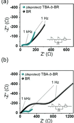
In an attempt to monitor the electrochemical behavior, EIS analysis was carried out for the (deprotect) TBA-b-BR and BR half-cells before cycling and after 50 cycles (Figure 4). The
Figure 3. a) Cycling performance of the NCM/Li–In all-solid-state half-cells
containing butadiene rubber (BR), poly(tert-butyl acrylate) (TBA), (depro-tect) TBA, poly(tert-butyl acrylate)-b-poly(1,4-butadiene) (TBA-b-BR), and (deprotect) TBA-b-BR binders when measured at 0.1C (19.5 mA g−1) and
25 °C. Areal loading of NCM711 active material = 8 mg cm−2. b) Cycling
performance of the NCM/Li–In all-solid-state half-cells containing BR, (deprotect) TBA, and (deprotect) TBA-b-BR binders when tested at 0.1C (19.5 mA g−1) and 25 °C. Areal loading of NCM711 active material = 16 mg cm−2.
c) Rate capability of the same two cells with the loading of NCM711 active material being 16 mg cm−2 when measured at various C-rates.
Figure 4. Electrochemical impedance spectroscopy (EIS) plots of the
NCM/Li–In all-solid-state half-cells containing butadiene rubber (BR) and (deprotect) poly(tert-butyl acrylate)-b-poly(1,4-butadiene) (TBA-b-BR) binders a) before cycling and b) after 50 charge−discharge cycles at 0.1C.
electrochemical behavior was fitted to an equivalent circuit (inset in Figure 4), which made it possible to obtain the resistance of the SE layer (RSE) and the charge transfer resistance (RCT) from the x-axis intercept and the amplitude of the semicircles in the Nyquist plots, respectively.[8e,24] The R
SE of all samples remained similarly near 10 Ω cm2 regardless of the cycle number, which can be interpreted to indicate that RSE consistently represents the intrinsic bulk resistance of the LPSCl. In contrast, the RCT of these cells increased significantly during cycling. Nonetheless, between both cells, the increase in RCT was more prominent with the BR cell than with the (deprotect) TBA-b-BR cell; the RCT of the BR cell increased from 62.2 to 508.5 Ω cm2 after 50 cycles, whereas that of the (deprotect) TBA-b-BR cell increased from 54.0 to 147.3 Ω cm2. The more significant increase in the RCT of the BR cell, once again, reflects loosened interparticle contact upon cycling.
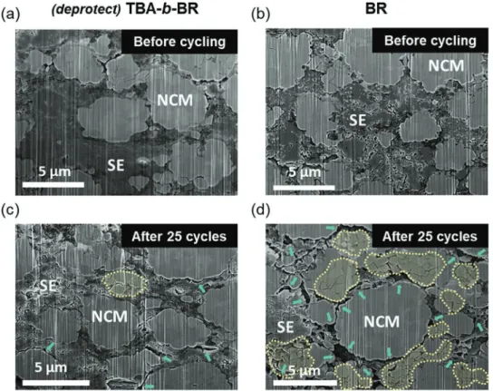
The distinct evolution of the interfacial resistance of both cells was anticipated to originate from the stability of inter-particle contact during cycling. To confirm this scenario, the microstructures of the cathode composite layers were visualized before and after charge−discharge cycles using cross-sectional scanning electron microscopy (SEM) (Figure 5 and Figure S12, Supporting Information). Prior to the cycling, all of the elec-trodes showed intimate interparticle contact and negligible voids (Figure 5a,b and Figure S12a, Supporting Information). After 25 cycles, the most discernible feature was the forma-tion of cracks in the active NCM711 particles; in the case of the (deprotect) TBA-b-BR electrode, the majority of active par-ticles appeared to be crack-free (Figure 5c), whereas the active
particles in the BR electrode exhibited a greater number of internal cracks as marked with yellow dotted lines in Figure 5d. The formation of these cracks is a well-known degradation mechanism of the high-Ni NCM family, with its origins in the anisotropic volume expansion of the active phase.[25] Apart from this, according to the same SEM image, disintegration of the NCM711 and SE particles was more severe in the BR electrode, as indicated by the green arrows. The worsened condition of the active-SE contacts represents[26] disconnected percola-tion paths for Li ion transport, which also explains the larger semicircle in the EIS profile of the BR electrode after 50 cycles (Figure 4b). The loosened interparticle contact as well as the interfacial degradation during cycling is an inherently prob-lematic aspect of ASSBs,[21d,27] although it is almost inevitable once the active material undergoes substantial volume change. All in all, stable interparticle contact resulting from enhanced adhesion of the binder plays a critical role in improving the cyclability of ASSBs, in addition to providing feasibility for large-scale processing.
Finally, our electrochemical assessment was expanded to test full-cells paired with graphite anodes. These NCM/graphite all-solid-state full-cells were fabricated by sequentially casting the composite cathode and electrolyte layers on Al foil via the doctor blade technique. The compositions of the cathode and SE layers were NCM711:LPSCl:super P:binder = 74.5:21.5:2:2 and LPSCl:binder = 97.5:2.5 in weight, respectively. The anode layer was also prepared via the same slurry casting pro-cess on nickel (Ni) foil and consisted of graphite, LPSCl, and binder in a weight ratio of 78:19.5:2.5. For the anodes,
Figure 5. a−d) Cross-sectional scanning electron microscopy (SEM) images of the composite cathode layers containing (deprotect) poly(tert-butyl
acrylate)-b-poly(1,4-butadiene) (TBA-b-BR) (a,c) and butadiene rubber (BR) (b,d) binders. Before cycling (a,b) and after 25 charge−discharge cycles at 0.1C (c,d).
BR binder was used because the hydrophobic nature of the graphite surface would not benefit from the binder design used for the cathode. The separately prepared cathode/SE layers and the anode layer were assembled via cold pressing to complete the cell. See the cross-section of the full-cell using plasma focused ion beam (FIB, Figure S13, Sup-porting Information). The n/p ratio, defined as the total capacity ratio between the negative and positive electrodes, was 1.2. We invoked high NCM711 loadings of 16 mg cm−2 to determine the practical viability of the present cell fabrication scheme involving the new binder. When cycled at 0.1C (19.5 mA gNCM−1) in the voltage range of 2.5−4.3 V (Figure 6a), the (deprotect) TBA-b-BR cell delivered reversible capacity of 153.4 mAh gNCM−1 in its first cycle and retained 85.5% of the initial capacity after 45 cycles (Figure 6b). Remarkably, the CE of this full-cell reached 99.5% at the 8th cycle and stayed above this value in the subsequent cycles (inset in Figure 6b). A control full-cell based on BR binder exhibited inferior capacity retention of only 42.8% after 30 cycles (Figure S14, Supporting Information). As men-tioned for the performance of the half-cells, stable cycling in the full-cell operation is attributed to increased and stable interparticle contact facilitated by enhanced adhesion of the binder.
In summary, we introduced a novel binder design based on protection−deprotection chemistry, which resolves the tricky issue of polarity compatibility among the three electrode com-ponents (solvent, binder, and SE) in the slurry solution. This task was accomplished by switching the polarity of the binder during the course of electrode fabrication via cleavage of the t-butyl protecting group. Upon deprotection, the polar carboxy lic acid group is exposed, which enables hydrogen bonding interaction with the NCM active material to enhance the adhesion strength drastically, even beyond the levels of established LIB electrodes. When examined in both all-solid-state half-cells and full-cell settings, the (deprotect) TBA-b-BR cell exhibited superior cycling and rate performance compared to that of the BR and its protected analog, revealing the critical role of the deprotection scheme in the key cell performance parameters. The improved electrochemical and adhesion properties are ascribed to tightened interparticle contact and the resulting improved interfacial stability. The present inves-tigation is the first demonstration of in situ polarity switching of the polymeric binder for solution-processible sulfide-based ASSBs and highlights the unique and useful nature of depro-tection chemistry when designing binders that need to be employed in combination with multiple slurry components with incompatible polarities.
Experimental Section
Materials: The argyrodite LPSCl used was bi-modal in terms of particle size: 2 and 0.7 μm. The Li0.5In counter electrode was prepared by mixing
Li (FMC Lithium Corp.) and In (Sigma-Aldrich, 99.99%) powder in the atomic ratio of 0.5:1 and compressing them in contact with the SE pellet during cell assembly. Poly(tert-butyl acrylate) (TBA) with a number-average molecular weight (Mn) of 143 000 g mol−1 and poly(tert-butyl
acrylate)-b-poly(1,4-butadiene) (TBA-b-BR) in which the TBA and BR blocks have Mn values of 20 000 and 130 000 g mol−1, respectively, were
purchased from Polymersource Inc. Polybutadiene rubber with a weight-average molecular weight (Mn) of ≈200 000 g mol−1 was purchased from
Sigma-Aldrich.
Characterization of Materials: The thermal behavior of the deprotection reaction was monitored by thermogravimetric analysis (TGA, Q500, TA Instruments). The thermograms of binders were obtained using DSC (DSC 4000, Perkin-Elmer). The characteristics of the chemical bonds of the TBA and TBA-b-BR binders before and after deprotection were analyzed by FT-IR (Tensor27, Bruker). The compatibility of the LPSCl SE with the binders was assessed by dispersing the LPSCl powder in 2.5 wt% binder solutions based on butyl butyrate and dried at 120 °C for 15 h. The same procedure was followed for the deprotected binders except that the drying temperature was raised to 160 °C. After the drying step, the crystal structures and bonding characteristics of the LPSCl were examined by performing XRD analysis (New D8 Advance, Bruker) and Raman spectroscopy (Raman, DXR2xi, Thermo), respectively. The peeling strength of the composite cathodes was evaluated by conducting a 180° peeling test using a universal testing machine (QM 100S, QMESYS). For this test, 3M scotch tape was attached to the electrode of 25 × 30 mm2 and was peeled off at a constant displacement rate
of 10 mm s−1 while the peeling force was continuously monitored. For mandrel tests, composite cathodes were prepared and were subjected to five bending−unbending cycles around the cylindrical mandrels with varying diameters (3−8 mm) . The cross-sectional images of the composite cathode layers before and after cycling were obtained using a FIB (Helios G4, Thermo Fisher Scientific). The cross-sectional images of the NCM/graphite full-cell were obtained using plasma focused ion beam (Helios G4 PFIB CXe Dual Beam, FEI Company).
Figure 6. a) The 1st and 45th charge−discharge profiles of the NCM/
graphite all-solid-state full-cell containing (deprotect) poly(tert-butyl acrylate)-b-poly(1,4-butadiene) (TBA-b-BR) binder at 0.1C (19.5 mA gNCM−1)
at 25 °C. Areal loading of NCM711 active material = 16 mg cm−2. b) Cycling
performance and Coulombic efficiencies of the same full-cell in (a) when measured at 0.1C for both charge and discharge.
Electrochemical Characterization: The Li ionic conductivities were measured by AC impedance analysis using a battery cycler (VSP, Bio-Logic). For this analysis, slurries containing the LPSCl electrolyte and binders in a weight ratio of 97.5:2.5 were prepared in butyl butyrate, dried completely, and then pelletized at 590 MPa. AC impedances were then measured in a symmetric cell configuration o f Al foil|LPSCl-binder composite layer|Al foil in the frequency range from 1 MHz to 0.1 Hz. The obtained impedance profiles w ere fi tted to th e equivalent circuit using the Z-view software. The ionic conductivity was determined by using the following relation: σ = L/Rb A, where
L, Rb, and A correspond to the thickness of the LPSCl electrolyte
layer, the bulk resistance, and the area of the LPSCl electrolyte layer, respectively. The electrochemical stability of the (deprotect) TBA-b-BR binder was examined by CV measurement in which the voltage was scanned at 0.1 mV s−1 in the potential range of 1.5–3.7 V versus Li–In. The binder films u sed i n t his a nalysis w ere p repared b y casting 10 wt% binder solutions based on butyl butyrate onto Al foil followed by heat treatment at 160 °C for 15 h. For the fabrication of the all-solid-state half-cells, the composite cathodes were prepared by first dispersing NCM711, LPSCl, super P, and binder in butyl butyrate in a weight ratio of 74.5:21.5:2:2, followed by casting on Al foil and drying at 120 °C for 15 h. The binders were deprotected by subjecting the electrodes to heat treatment at 160 °C for 15 h for in situ deprotection and then maintained at room temperature under vacuum for 24 h. The cell assembly was fabricated by first p elletizing 1 00 m g o f L PSCl to the SE layer by cold-pressing it at 120 MPa, followed by positioning the composite cathode layer underneath the SE layer. The anode layer composed of Li0.5In was then placed on top of the SE layer.
Subsequently, the assembled cell was compressed at pressure of 590 MPa. Al and Cu foils were used as the cathode and anode current collectors, respectively. After the compression, the cell was positioned in a housing case that was internally fabricated for pressure control during cell testing. The torque applied during cell tests was 12 Nm. The electrochemical performance of the all-solid-state half-cells was galvanostatically assessed in the potential range of 1.88–3.68 V versus Li–In using a battery cycler (MACCOR series 4000). Both the charge and discharge were proceeded in constant current constant voltage (CCCV) mode, and the C-rate was defined a s 1 C = 1 95 m A g−1
. T he
NCM711/graphite all-solid-state full-cells were fabricated by preparing the composite cathode electrodes via the same procedure as for the half-cells. Electrolyte slurries consisting of LPSCl and BR binder in butyl butyrate in a weight ratio of 97.5:2.5 were cast onto the completely dried cathode layer, followed by heat treatment at 160 °C for 15 h. Anode slurries were prepared by dispersing graphite, LPSCl, and BR binder in butyl butyrate in a weight ratio of 78:19.5:2.5 and were cast onto Ni foil using the doctor blade technique, followed by heat treatment at 120 °C for 1 h and subsequent drying at room temperature under vacuum for 24 h. The cell was assembled by placing the composite anode layer on the LPSCl-cathode assembly and compressed at 490MPa. The n/p ratio (the areal capacity ratio between the negative and positive electrodes) was 1.2. After compression, the cell was positioned in the same housing case as in the half-cell tests. All assembly processes were carried out in an Ar-filled glove box.
Supporting Information
Supporting Information is availableAcknowledgements
The authors acknowledge financial support from a National Research Foundation of Korea grant (NRF-2017M1A2A2044504) and generous support from the Institute of Engineering Research (IER) at Seoul National University.
Conflict of Interest
The authors declare no conflict of interest.
Keywords
acrylate polymers, argyrodite, polarity switching, protection−deprotection chemistry, thermolysis
[1] a) M. Armand, J.-M. Tarascon, Nature 2008, 451, 652; b) J. B. Goodenough, Y. Kim, Chem. Mater. 2010, 22, 587.
[2] a) Y. Seino, T. Ota, K. Takada, A. Hayashi, M. Tatsumisago, Energy Environ. Sci. 2014, 7, 627; b) Y. Wang, W. D. Richards, S. P. Ong, L. J. Miara, J. C. Kim, Y. Mo, G. Ceder, Nat. Mater. 2015, 14, 1026; c) M. Tatsumisago, M. Nagao, A. Hayashi, J. Asian Ceram. Soc.
2013, 1, 17.
[3] a) A. Manthiram, X. Yu, S. Wang, Nat. Rev. Mater. 2017, 2, 16103; b) S. Wenzel, D. A. Weber, T. Leichtweiss, M. R. Busche, J. Sann, J. Janek, Solid State Ionics 2016, 286, 24; c) K. H. Park, Q. Bai, D. H. Kim, D. Y. Oh, Y. Zhu, Y. Mo, Y. S. Jung, Adv. Energy Mater.
2018, 8, 1800035.
[4] N. Kamaya, K. Homma, Y. Yamakawa, M. Hirayama, R. Kanno, M. Yonemura, T. Kamiyama, Y. Kato, S. Hama, K. Kawamoto, Nat. Mater. 2011, 10, 682.
[5] Y. Kato, S. Hori, T. Saito, K. Suzuki, M. Hirayama, A. Mitsui, M. Yonemura, H. Iba, R. Kanno, Nat. Energy 2016, 1, 16030. [6] a) S. Boulineau, M. Courty, J.-M. Tarascon, V. Viallet, Solid
State Ionics 2012, 221, 1; b) C. Yu, L. van Eijck, S. Ganapathy, M. Wagemaker, Electrochim. Acta 2016, 215, 93; c) H. J. Deiseroth, S. T. Kong, H. Eckert, J. Vannahme, C. Reiner, T. Zaiss, M. Schlosser, Angew. Chem., Int. Ed. 2008, 47, 755; d) J. Auvergniot, A. Cassel, J.-B. Ledeuil, V. Viallet, V. Seznec, R. m. Dedryvère, Chem. Mater.
2017, 29, 3883; e) C. Yu, S. Ganapathy, N. J. J. de Klerk, I. Roslon,
E. R. H. van Eck, A. P. M. Kentgens, M. Wagemaker, J. Am. Chem. Soc. 2016, 138, 11192.
[7] J. Schnell, T. Günther, T. Knoche, C. Vieider, L. Köhler, A. Just, M. Keller, S. Passerini, G. Reinhart, J. Power Sources 2018, 382, 160. [8] a) K. Lee, S. Kim, J. Park, S. H. Park, A. Coskun, D. S. Jung, W. Cho,
J. W. Choi, J. Electrochem. Soc. 2017, 164, A2075; b) K. Lee, J. Lee, S. Choi, K. Char, J. W. Choi, ACS Energy Lett. 2019, 4, 94; c) T. Inada, K. Takada, A. Kajiyama, M. Kouguchi, H. Sasaki, S. Kondo, M. Watanabe, M. Murayama, R. Kanno, Solid State Ionics 2003, 158, 275; d) A. Sakuda, K. Kuratani, M. Yamamoto, M. Takahashi, T. Takeuchi, H. Kobayashi, J. Electrochem. Soc. 2017, 164, A2474; e) D. Y. Oh, D. H. Kim, S. H. Jung, J.-G. Han, N.-S. Choi, Y. S. Jung, J. Mater. Chem. A 2017, 5, 20771; f) M. Yamamoto, Y. Terauchi, A. Sakuda, M. Takahashi, Sci. Rep. 2018, 8, 1212; g) Y. J. Nam, D. Y. Oh, S. H. Jung, Y. S. Jung, J. Power Sources 2018, 375, 93; h) T. Ates, M. Keller, J. Kulisch, T. Adermann, S. Passerini, Energy Storage Mater. 2019, 17, 204; i) J. Zhang, H. Zhong, C. Zheng, Y. Xia, C. Liang, H. Huang, Y. Gan, X. Tao, W. Zhang, J. Power Sources 2018, 391, 73.
[9] D. H. Tan, A. Banerjee, Z. Deng, E. A. Wu, H. Nguyen, J.-M. Doux, X. Wang, J.-h. Cheng, S. P. Ong, Y. S. Meng, ACS Appl. Energy Mater.
2019, 2, 6542.
[10] N. Riphaus, P. Strobl, B. Stiaszny, T. Zinkevich, M. Yavuz, J. Schnell, S. Indris, H. A. Gasteiger, S. J. Sedlmaier, J. Electrochem. Soc. 2018, 165, A3993.
[11] S. Ito, S. Fujiki, T. Yamada, Y. Aihara, Y. Park, T. Y. Kim, S.-W. Baek, J.-M. Lee, S. Doo, N. Machida, J. Power Sources 2014, 248, 943. [12] N. C. Rosero-Navarro, T. Kinoshita, A. Miura, M. Higuchi,
K. Tadanaga, Ionics 2017, 23, 1619.
[13] P. Bisel, L. Al-Momani, M. Müller, Org. Biomol. Chem. 2008, 6, 2655. [14] N. D. Treat, N. Ayres, S. G. Boyes, W. J. Brittain, Macromolecules
2006, 39, 26.
[15] a) Y. Shi, X. Zhou, G. Yu, Acc. Chem. Res. 2017, 50, 2642; b) A. Magasinski, B. Zdyrko, I. Kovalenko, B. Hertzberg, R. Burtovyy, C. F. Huebner, T. F. Fuller, I. Luzinov, G. Yushin, ACS Appl. Mater. Interfaces 2010, 2, 3004.
[16] a) Y.-H. La, E. W. Edwards, S.-M. Park, P. F. Nealey, Nano Lett.
2005, 5, 1379; b) J. Y. Kelly, J. N. Albert, J. A. Howarter, S. Kang,
C. M. Stafford, T. H. Epps III, M. J. Fasolka, ACS Appl. Mater. Inter-faces 2010, 2, 3241; c) J. Schaefgen, I. Sarasohn, J. Polym. Sci., Part A: Polym. Chem. 1962, 58, 1049.
[17] a) J. Duvigneau, S. Cornelissen, N. Bardají Valls, H. Schönherr, G. J. Vancso, Adv. Funct. Mater. 2010, 20, 460; b) J. Duvigneau, H. Schönherr, G. J. Vancso, Langmuir 2008, 24, 10825.
[18] S. Yubuchi, M. Uematsu, M. Deguchi, A. Hayashi, M. Tatsumisago, ACS Appl. Energy Mater. 2018, 1, 3622.
[19] S. Yubuchi, S. Teragawa, K. Aso, K. Tadanaga, A. Hayashi, M. Tatsumisago, J. Power Sources 2015, 293, 941.
[20] a) J. He, L. Zhang, J. Alloys Compd. 2018, 763, 228; b) J. Chong, S. Xun, H. Zheng, X. Song, G. Liu, P. Ridgway, J. Q. Wang, V. S. Battaglia, J. Power Sources 2011, 196, 7707.
[21] a) Y. Zhu, X. He, Y. Mo, ACS Appl. Mater. Interfaces 2015, 7, 23685; b) S. Wenzel, S. J. Sedlmaier, C. Dietrich, W. G. Zeier, J. Janek, Solid State Ionics 2018, 318, 102; c) S. H. Kim, K. Char, S. I. Yoo,
B. H. Sohn, Adv. Funct. Mater. 2017, 27, 1606715; d) W. Zhang, F. Richter, S. P. Culver, T. Leichtweiß, J. G. Lozano, C. Dietrich, P. G. Bruce, W. G. Zeier, J. Janek, ACS Appl. Mater. Interfaces 2018, 10, 22226.
[22] a) R. Koerver, I. Aygün, T. Leichtweiß, C. Dietrich, W. Zhang, J. O. Binder, P. Hartmann, W. G. Zeier, J. Janek, Chem. Mater.
2017, 29, 5574; b) R. Koerver, W. Zhang, L. de Biasi, S. Schweidler,
A. O. Kondrakov, S. Kolling, T. Brezesinski, P. Hartmann, W. G. Zeier, J. Janek, Energy Environ. Sci. 2018, 11, 2142; c) F. Walther, R. Koerver, T. Fuchs, S. Ohno, J. Sann, M. Rohnke, W. G. Zeier, J. Janek, Chem. Mater. 2019, 31, 3745.
[23] J. Zhang, C. Zheng, L. Li, Y. Xia, H. Huang, Y. Gan, C. Liang, X. He, X. Tao, W. Zhang, Adv. Energy Mater. 2020, 10, 2070017.
[24] Z. Zhang, L. Zhang, Y. Liu, C. Yu, X. Yan, B. Xu, L.-M. Wang, J. Alloys Compd. 2018, 747, 227.
[25] a) A. O. Kondrakov, A. Schmidt, J. Xu, H. Geßwein, R. Mönig, P. Hartmann, H. Sommer, T. Brezesinski, J. Janek, J. Phys. Chem. C 2017, 121, 3286; b) A. O. Kondrakov, H. Geßwein, K. Galdina, L. de Biasi, V. Meded, E. O. Filatova, G. Schumacher, W. Wenzel, P. Hartmann, T. Brezesinski, J. Phys. Chem. C 2017, 121, 24381. [26] a) Y. Ito, M. Otoyama, A. Hayashi, T. Ohtomo,
M. Tatsumisago, J. Power Sources 2017, 360, 328; b) W. Zhang, D. A. Weber, H. Weigand, T. Arlt, I. Manke, D. Schröder, R. Koerver, T. Leichtweiss, P. Hartmann, W. G. Zeier, ACS Appl. Mater. Inter-faces 2017, 9, 17835; c) J. A. Lewis, J. Tippens, F. J. Q. Cortes, M. T. McDowell, Trends Chem. 2019, 1, 845.
[27] a) W. Zhang, D. Schröder, T. Arlt, I. Manke, R. Koerver, R. Pinedo, D. A. Weber, J. Sann, W. G. Zeier, J. Janek, J. Mater. Chem. A 2017, 5, 9929; b) Z. D. Hood, M. Chi, J. Mater. Sci. 2019, 54, 10571.