HAL Id: hal-03027950
https://hal.laas.fr/hal-03027950
Submitted on 27 Nov 2020
HAL is a multi-disciplinary open access archive for the deposit and dissemination of sci-entific research documents, whether they are pub-lished or not. The documents may come from teaching and research institutions in France or abroad, or from public or private research centers.
L’archive ouverte pluridisciplinaire HAL, est destinée au dépôt et à la diffusion de documents scientifiques de niveau recherche, publiés ou non, émanant des établissements d’enseignement et de recherche français ou étrangers, des laboratoires publics ou privés.
Experimental Dosimetry Study of a Miniature RF
Applicator Dedicated to the Evaluation of Severe RF
Exposure Impact on a 3D Biological Model
Sylvain Auge, Amar Tamra, L. Rigal, V. Lobjois, B. Ducommun, David
Dubuc, Katia Grenier
To cite this version:
Sylvain Auge, Amar Tamra, L. Rigal, V. Lobjois, B. Ducommun, et al.. Experimental Dosimetry Study of a Miniature RF Applicator Dedicated to the Evaluation of Severe RF Exposure Impact on a 3D Biological Model. 2020 IEEE/MTT-S International Microwave Symposium (IMS), Aug 2020, Los Angeles, United States. pp.508-511, �10.1109/IMS30576.2020.9223806�. �hal-03027950�
Experimental Dosimetry Study of a Miniature RF Applicator
Dedicated to the Evaluation of Severe RF Exposure Impact
on a 3D Biological Model
S. Augé
1, A. Tamra
1, L. Rigal
2, V. Lobjois
2, B. Ducommun
2,3, D. Dubuc
1, K. Grenier
1 1LAAS-CNRS, Université de Toulouse, CNRS, UPS, Toulouse, France
2
Université de Toulouse, ITAV, CNRS, UPS, Toulouse, France
3CHU de Toulouse, Toulouse, France
Abstract— The impact of RF radiation on the living
constitutes a controversial topic, whereas wireless applications continue to grow drastically and our daily environment is surrounded of electromagnetic fields. In order to evaluate the potential impact of RF radiations even with severe RF exposures, it is important to conduct experiments with a very well controlled dosimetry and with calibrated RF exposure systems. In this paper, a miniature RF applicator, which enables to apply controlled electromagnetic fields radiation on micro-tissues, is introduced. An experimental method based on thermal measurements has been developed in such a micro-device to define the Specific Absorption Rate applied to micro-tissues depending on the applied power and the thermal increment in steady state. Due to miniature configuration of the applicator, a large range of SAR may be achieved in moderate thermal conditions.
Keywords—micro-dosimetry, RF applicator,
microtechnologies, RF effects, biological cells, micro-tissues, SAR
I. INTRODUCTION
ElectroMagnetic (EM) fields are widely used for civil and military applications. In addition to the wireless standards and applications, such as the 5G transfer data generation, the connected objects, wireless power transfer and wireless implants, radars and EM-based weapon equipment for electronic warfare for example are increasing of interest and development. It includes not only low or medium RF exposure ranges (with Specific Absorption Rate -SAR- up to few W/kg, below or close to ICNIRP recommendations), but also severe ones with kW/kg values. The evaluation of potentially harmful effects on the living due to electromagnetic fields is consequently imperative. This is even more true that the interaction phenomena between EM fields and the living are far from being completely known.
Numerous studies related to RF exposure systems and RF effects have already been conducted in the past [1-7]. Some are revealing harmful effects, with even the appearance of different cancers on rats [8-11], whereas others do not present any EM effect on the living. To contribute to this controversial topic, it is important therefore important to use or develop (1) precise and controlled RF exposure systems, which are well characterized in terms of SAR, EM field intensity, thermal increment, with a clear description of the applied RF signal, (2)
with high range of SAR values, low, medium and up to severe level RF exposures.
In vitro evaluations of EM fields are traditionally
performed with cell cultures grown as monolayer (2D) in Petri dishes. This cellular configuration presents however limitations, as far from real in vivo behavior. Moreover, due to ethic issues, there is a strong interest in developing RF exposure systems, which could avoid the use of animal testing while being biologically relevant. Employing micro-tissues, e.g mastered organized 3D aggregates of cells, is particularly attractive, as they present a strong cellular heterogeneity, which confers an intermediate level of this model toward in
vivo investigations.
To our best knowledge, there is no RF applicator, which has been developed so far to radiate any controlled RF signals on micro-tissues from low to severe level RF exposures. This paper introduces such a structure and a method applied to characterize its SAR and its thermal increment depending on the applied RF power.
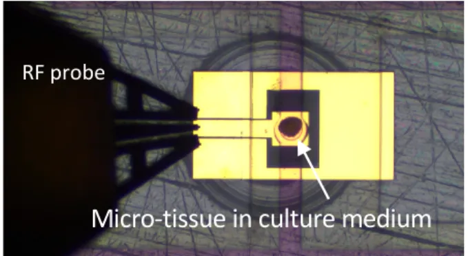
Fig. 1. Photography of a RF applicator adapted to micro-tissue.
This paper first introduces the advantages of using a 3D biological model, called micro-tissue. A description and a microwave characterization of the developed RF exposure applicator appropriate to radiate micro-tissues with controlled EM fields is then be given in the next section, as well as its technology. The section 4 presents then the experimental
CPW access Fluidic walls
dosimetry study developed to characterize the SAR and thermal increment within the miniature RF applicator. Finally, RF exposures are performed on micro-tissues and evaluated in term of genotoxic effect with DNA damages detection.
II. MATERIALS AND METHODS
A. Micro-tissue: a 3D biological model
Traditionally, 2D monolayer cell cultures are used for cellular-based dosimetric investigations. However, these biological models are not relevant of in vivo behavior.
On the other side, 3D multicellular models, also called micro-tissues, are constituted of an aggregate of multiple cells and exhibit important cellular heterogeneity, regionalization of growth and strong interactions between cells. The main interest of such a model is that it may reproduce in vitro the heterogeneity of a tissue at a lower complexity level, without requesting in vivo investigations and therefore animal testing.
Such 3D micro-tissues exhibit a rounded shape and present increasing diameters as they continue to proliferate and grow naturally while kept in culture medium with appropriate environmental conditions. Due to microfabrication constraints, 250 to 300 µm large micro-tissues have been chosen for our experiments.
B. Architecture description of the RF applicator, specific to radiate micro-tissues with controlled RF signals
As shown with the photography of Fig. 1, the miniature RF applicator is composed of a first coplanar section, which enables the positioning of a RF probe. While the coplanar grounds are merged on the opposite side of the device, the central conductor is ended by a capacitive patch in the middle of two fluidic walls. The micro-tissue under test is localized in the center part of the conductive open-ended transmission line section.
Fig. 2. Schematic of the RF applicator suited for micro-tissue exposure.
The fluidic walls permit to maintain the micro-tissue in a culture medium, providing all nutrients necessary to the living cells. As the fluidic walls present a thickness of 500 µm, there is no liquid where the RF probe is applied. All dimensions are given in Fig. 2.
For the experiments, the fluidic channel is loaded with the culture medium of the micro-tissues, Dulbecco's Modified Eagle Medium (DMEM) in our case. To characterize the fabricated microdevice up to 40 GHz, the device under test is connected to a Vector Network Analyser using a coplanar RF probe and a coaxial cable, using a preliminary SOLT calibration step. The measured S11 module is then compared to the simulated one in Fig. 3, while the structure is loaded with DMEM. The good agreement between the two curves validates the fabrication of the micro-device.
Fig. 3. Simulated and measured S parameter of the device loaded with cell culture medium.
At 2.45 GHz, the device is highly reflective (|S11|=0.974 at 2.45 GHz). This is due to the low DMEM volume fraction combined with the moderate loss tangent of DMEM, exhibiting a 0.27 value at this frequency. This will have an impact on the SAR values, as only 5% of the incident power is dissipated within the DMEM liquid. Nevertheless, section IV will experimentally demonstrate that high (severe) SAR values may be reached.
C. RF applicator technology
The RF applicator fabrication involves three main steps based on standard microtechnology processes. First, the RF applicator is realized on top of a quartz substrate, which has been preliminary cleaned with different chemical baths. The RF metallization is then performed using a lift-off technique. The obtained waveguide is composed of a flash of titanium to enable the metal adhesion on the substrate, followed by a gold layer of 0.3 µm thick. To avoid any spreading and disassembling of the micro-tissue within the fluidic channel, a 5 µm thick isolation layer is deposited and patterned. 500 µm fluidic walls are finally realized on top, while keeping the micro-tissue in its liquid environment during the experiments. Moreover, the choices of all constitutive materials have been done to make the structure totally biocompatible.
III. EXPERIMENTAL DOSIMETRY METHODOLOGY
To experimentally predict the SAR level within the micro-structure, a methodology has been selected, which consists in measuring the transient temperature immediately after RF exposure. Fluidic walls Ground Ground Signal μ-tissue location 0,4 0,5 0,6 0,7 0,8 0,9 1 0 10 20 30 40 1 0.9 0.8 0.7 0.6 0.5 0.4 Frequency (GHz) S1 1 Simulation Measure
A. Experimental test setup
In the homogeneous host liquid, which is initially at thermal equilibrium, the SAR is related to the derivative of the temperature with respect to time, as long as no significant effect due to thermal conduction appears. This last requirement is obtained just after applying the RF exposure. The corresponding relationship is given by the following equation:
𝑆𝐴𝑅 = 𝑐
'(') (1)
where the SAR is in W/kg, cis the specific heat capacity of the liquid in J/kg/K, dT is the change in temperature in K during dt in seconds.
To perform the dosimetry investigation, a test setup has been defined. The corresponding schematic is given in Fig. 4.
Fig. 4. Test setup used to evaluate the SAR within the fluidic cavity.
The experimental test setup is composed of two parts, one dedicated to the RF signal generation and exposure, whereas the second one is related to the thermal measurements.
The RF power delivery part is composed of a RF generator followed by a power amplifier, which both enable to deliver a power level up to 30 dBm. The RF signal is then conveyed to the miniature RF applicator through a directional coupler, a cable and a RF probe. The coupler is in charge of monitoring the reflected power (5% of the incident one at 2.45 GHz) and permits (1) to monitor the dissipated power and (2) to detect the malfunction of the micro-device.
The thermal part includes a fiber optic temperature sensor connected to a signal conditioner. The tip of the sensor only exhibits a size of 120 µm wide, which is compatible with the 300 µm width of the fluidic channel. This fiber is placed in the vicinity of the isolation layer and permits to accurately measure the temperature modification within the fluidic channel, in place of the micro-tissue. Temperature versus time may then be measured with such an equipment.
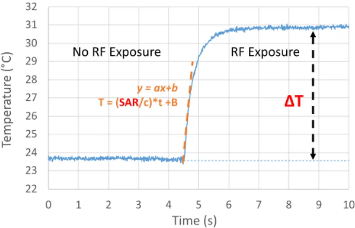
B. SAR prediction methodology
The methodology is based on the analysis of temperature readings as a function of time, before and after RF exposure. An example of obtained curve is given in Fig. 5.
The SAR is extracted from the slope of the temperature versus time curve as soon as the RF exposure is applied. This slope is indicated with the orange dashed line in Fig. 5. SAR/c therefore corresponds to the “a” coefficient of the curve. Such a measurement also enables to evaluate the thermal increment in steady state (ΔT indicated in red in Fig. 5).
Moreover, the SAR depends on the power generated at the output of the power amplifier. Theoretically, a proportional relationship exists between these two quantities. Each evaluated SAR will consequently be normalized with respect to the injected power.
Fig. 5. Example of a temperature modification measured within the fluidic cavity versus time.
Next section is dedicated to the experimental results. IV. EXPERIMENTAL DOSIMETRY RESULTS
A RF signal at 2.45 GHz in CW mode has been used for the experiments. Beside the SAR, it is important to know if the experiment is in a thermal or an athermal regime. This is the reason why the thermal increment has been studied, which is also theoretically proportional to the output power of the amplifier. A 20 dBm source power level of the output power of the power amplifier has been tested. This enables a sufficiently sensitive measurement to determine both thermal increment and the slope of the time-dependent temperature curve.
Table 1 presents the experimental results obtained for the thermal increment and the SAR, both normalized with respect to the source power in mW.
Table 1. Normalized thermal increment and SAR value.
A non-significant thermal increment inferior to 0.1°C corresponds to SAR value of several hundred W/kg.
Consequently, in athermal conditions and using the microdevice combined to medium power RF equipment, SAR values up to hundred, even thousand W/kg may be reached, which may be relevant for specific severe RF exposures studies (such as microwave based anti-personnel weapons for instance in military applications). With microfluidics, the surface area to volume ratio indeed increases, which translates Generator P meter Coupler cable Power amplifier PA RF probe Micro-device Host liquid Fluidic walls Thermal probe T meter 22 23 24 25 26 27 28 29 30 31 32 0 1 2 3 4 5 6 7 8 9 10 Te m pe ra tu re (° C) Time (s) y = ax+b T = (SAR/c)*t +B
ΔT
RF Exposure No RF Exposureto high SAR values generated with a moderate thermal increment.
Additionally, the “microscale” setup may also generate conditions in the range of W/kg and below, with thermal increase lower than one thousandth degree, which is highly non-significant.
V. BIOLOGICAL EXPERIMENTS
After RF exposure, RF radiated micro-tissues are collected and analysed with traditional biological equipment. Depending on the employed techniques, further understanding of the interaction mechanisms of EM fields on living cells may be reached.
In this experiment, RF genotoxic effects are targeted. Four replicated sample types are considered:
- the RF exposed micro-tissues,
- others, which are similarely prepared and placed apart to constitute the negative control,
- the mock ones, which correspond to micro-tissues submitted to all the manipulations involved during the experiment without RF illumination, e.g. also placed in the micro-devices without application of EM fields,
- and finally, the positive controls, i.e. micro-tissues submitted to a chemical treatment known as generating DNA damages. Fig. 6 presents the photography of a micro-tissue positioned in the center of the RF applicator. The micro-tissue is maintained in its culture medium, visible on the picture as the pink liquid within the fluidic channel.
Fig. 6. Photography of an RF applicator under test, loaded with a micro-tissue.
After manipulation or RF exposure, micro-tissues are fixed and cryo-sectioned, then analysed by immunofluorescence using the γH2AX label, a nuclear marker which is specific to the detection of DNA strand breaks (DNA damage). Fig. 7 presents examples of images for each type of micro-tissues.
Fig. 7. Example of labeled images obtained after γH2AX immunolabelling for the 4 micro-tissues samples : negative control, positive control, mock and
RF exposed. Scale bar : 100 µm.
As expected, the positive control presents many positive nuclei, related to DNA damages, whereas the negative control, the mock and the RF exposed micro-tissues do not present significative labelling for an applied SAR of 59 kW/kg for 15 min at 2.45 GHz.
VI. CONCLUSIONS
To conclude, this paper presents a miniature RF applicator, which enables to apply controlled electromagnetic fields on micro-tissues. Such a biological model presents the major advantage of exhibiting a cellular complexity and heterogeneity close to the one present in living entities, such as animals and humans, without requesting animal testing. To perform a dosimetry study of the device, a dedicated test setup and a measurement method have been defined to obtain both thermal increment and SAR values for different applied powers. Due to the miniature size of the device, a large range of SAR values may be reached in athermal condition, which may present interest for specific applications, including severe RF exposures. Finally, such a device allied to biological post-analysis on micro-tissues enables investigations toward a further comprehension of the EM fields interaction mechanisms at the cellular level.
ACKNOWLEDGMENT
This work was supported in part by French projects, grant Plan Cancer Env 2012-RF3DDR, grant n° EST-16 RF-07 from ANSES, and grant n° ANR-15-ASTR-0017 from ANR and DGA, and in part by LAAS-CNRS micro and nano technologies platform, member of the French RENATECH network.
REFERENCES
[1] T. Wu, T.S. Rappaport, C.M. Collins, “Safe for generations to come,” IEEE Microwave Magazine, pp. 65-84, March 2015.
[2] A. Paffi et al., “Considerations for Developing an RF Exposure System: A Review for in vitro Biological Experiments,” IEEE T-MTT, vol. 58, n°12, pp. 2702-2714, 2010.
[3] M. Zhadobov et al., “Exposure System and Dosimetry for In Vitro Studies of Biocompatibility of Pulse-Modulated RF Signals of Ultrahigh Field MRI,” IEEE Trans. On Biomed. Eng., vol. 60, n° 11, pp. 3167-3175, Nov. 2013.
[4] A. Perrin et al., “Evaluation of the co-genotoxic effects of 1800 MHz GSM radiofrequency exposure and a chemical mutagen in cultured human cells,” C. R. Physique, vol. 11, pp. 613-621, 2010.
[5] J. Schuderer et al., “In vitro exposure systems for RF exposures at 900 MHz,” IEEE T-MTT, vol. 52, n°8, pp. 2067-2075, Aug. 2004. [6] D. Habauzit et al., “Transcriptome Analysis Reveals the Contribution
of Thermal and the Specific Effects in Cellular Response to Millimeter Wave Exposure,” PLOS ONE, vol.9, n°10, e109435, Oct. 2014. [7] C. Merla et al., “Microdosimetry for nanosecond pulsed electric field
applications: a parametric study for a single cell,” IEEE Trans. On Biomed. Eng., vol. 58, n° 5, pp. 1294-1302, May 2011.
[8] J.C. Lin, “Cancer Occurrences in Laboratory Rats from Exposure to RF and Microwave Radiation,” IEEE JERM, pp. 2-13, doi:10.1109/jerm.2017.2721427, 2017
[9] M. Wyde et al, “Report of Partial findings from the National Toxicology Program Carcinogenesis Studies of Cell Phone Radiofrequency Radiation in Hsd: Sprague Dawley® SD rats (Whole Body Exposure),” bioRxiv 055699; doi: https://doi.org/10.1101/055699 [10] J.C. Lin, “Human exposure to RF, microwave and millimeterwave-electromagnetic radiation,” IEEE Microwave Magazine, pp. 32-36, June 2016.
Micro-tissue in culture medium
RF probe NT Mock RF 20dBm Etoposide DA P I γH2 A X