Publisher’s version / Version de l'éditeur:
Engineering Journal, 44, 1, pp. 35-41, 1961-01
READ THESE TERMS AND CONDITIONS CAREFULLY BEFORE USING THIS WEBSITE. https://nrc-publications.canada.ca/eng/copyright
Vous avez des questions? Nous pouvons vous aider. Pour communiquer directement avec un auteur, consultez la première page de la revue dans laquelle son article a été publié afin de trouver ses coordonnées. Si vous n’arrivez pas à les repérer, communiquez avec nous à [email protected].
Questions? Contact the NRC Publications Archive team at
[email protected]. If you wish to email the authors directly, please see the first page of the publication for their contact information.
NRC Publications Archive
Archives des publications du CNRC
This publication could be one of several versions: author’s original, accepted manuscript or the publisher’s version. / La version de cette publication peut être l’une des suivantes : la version prépublication de l’auteur, la version acceptée du manuscrit ou la version de l’éditeur.
Access and use of this website and the material on it are subject to the Terms and Conditions set forth at
A new Canadian structural test installation
Schriever, W. R.; Plewes, W. G.
https://publications-cnrc.canada.ca/fra/droits
L’accès à ce site Web et l’utilisation de son contenu sont assujettis aux conditions présentées dans le site
LISEZ CES CONDITIONS ATTENTIVEMENT AVANT D’UTILISER CE SITE WEB.
NRC Publications Record / Notice d'Archives des publications de CNRC:
https://nrc-publications.canada.ca/eng/view/object/?id=38bf6860-a12e-44b6-b5c7-9ed485265368
https://publications-cnrc.canada.ca/fra/voir/objet/?id=38bf6860-a12e-44b6-b5c7-9ed485265368
Ser
fH].
N2lt2
no. 1L5
e . 2
BI.DG
NATIONAL RESEARCH COUNCIL
CANADA
DIVISION OF BUILDING RESEARCH
By
A NEW CANADIAN STRT]CTT]RAL
TTST INSTALLATION
W. R. Schriever and W. G. Plewes
A N A L Y Z E D
REPRINTED FROM
THE ENGINEERING JOURNAL
voL. 44 NO. 1 IANUARY 1961, P. 35-4r
TECHNICAL PAPER NO. 115
O,F THE
DIVISION OF BUILDING RESEARCTI
OTTAWA
IANUARY 196r
B U I L D I I { G R E S E A R C H- LIBRARY
-F E B 2 L 1 9 6 l
N A T I O N A L R E S E A R C H C O U N C I LNRC 6166
PRICE TO CENTS
eo59
.3L.C',/7e
This publication is being distributed by the Division of Building Research of the National Research Council as a contribution towards better building in Canada. It should not be reproduced in whole or in part, without pemission of the original publisher. The Division would be glad to be of assistance in obtaining such permission.
Publications of the Division of Building Research may be obtained by mailing the appropriate remittance, (a Bank, Express, or Post Office Money C)rder or a cheque made payable at par in Ottawa, to the Receiver General of Canada, credit National Resealch Council) to the National Research Council, Ottawa. Stamps ale not accepbable.
A coupon sy. relatively simple and may be ol colrpons rntry b licetiorrs irrclud Board. - 'ications rents, 'hese puD-tions NRC 6166
A New Canadian
STRUCTURAL
TEST INSTALLATION
W. R. Schriever, M.E.I.c.,
Head, Building Structures Section, Ditsision of Building Research, N ational Research C ouncil, Ottaa a.
W. G. Plewes, M.E.I.c.,
Research Offi,cer, Buililing Structures Section, Dioi.sion of Building Research,
N ationnl Resear ch C ouncil. Ottaaa.
iii+iiiii;iiiiiiiiiilil:i#l:li+t:i.:E
This
installation
provides
universal
facility
for loading
tests
on
such
structural
components
as beams,
slabs,
columns,
roofs
and
walls.
lt was
installed
in NRC's
Division
of Building
Research.
i:iliiiii:;iiiiiiiii'i',n:ii:l:tiir.r'i.:I,iiri#i:ii.iiL1t.:i+liiiiil;ii':;i+,$ilYi#:llii+ Presented at the 74th E.LC. Annual General Meeting, Winnipeg, May 1960.
Summary
The three main parts of this
installation are (i) a strong rein-forced concrete test floor, (ii) a set of steel frames to be assembled, around the test object and anchored to the floor and (iii) portable hydraulic jacks for the application of the loads. The test floor, with a maximum length of 54 ft. provides 42 regularly spaced anchorage points for the structural steel frames and has been designed
to withstand vertical or horizontal
forces of up to 50 tons at each of
these points. In resisting upward
forces, use is made of the weight of the underlying bedrock through spec-ial pretensioned rock anchors. The structural steel reaction frafnes are connected to the slab and to each o'ther by torqued high-strength steel bolts to provide maximum rigidity. Tlhe portable jacks range in capacity from 2tA to 50 'tons and are suitable both for static and dynamic testing,
are of the lapped-piston type and
provide an accuracy in load measure-ment comDarable to that of a uni-versal testiirg machine. The Paper de-scribes the design and construction of this installation and makes reference
to install'artions in other countries.
rF HE behavioul of structules undcr'
I actual loading and the interaction
between various components of a structure have of recent years be-come the subject of increased inter-est to structural engineers. In the past,
structulal design has usually been
based on assumptions of (i) elastic be-haviour, (ii) homogeneous materials and (iii) an assemblage of elemerits acting independently. Research has shown that these assumptions
fre-quently do not lead to an accurate assessment of the actual strength of a structure because of complicated interaction of components or because the behaviour changes significantly as the range of true elastic behaviour is exceeded.
To investigate this interaction of
components and the behaviour of various structures under actual load-ing it is often desirable to observe structures in the field or to conduct loading tests on full scale structures or assemblages of components in order to develop a more complete under-standing of structural behaviour up to and including failure. Loading tests to failure are particularly important since it is frequently difficult to pre-dict the true margin of safety of a structure from stress calculations in the elastic range.
The Division of Building Researcilr of the National Research Council, and
particularly its Building Structures
Section which is concerned, with the strength and deformation character-istics of structures and the loads
act-ing upon 'them, has frequently
en-countered the need for sucih loading tests. In the past this called for special equipment, often designed or impro-vised for a single 'test. Tests had to be made on structures such as house
com,ponents, r'oof trusses, beams,
floors and walls. With improvised
equipment it was often difficult to develop the large forces and reactions necessary to reach failure. Ordinaly universal testing machines were found to be very limited in their application to such testing because they were not
sufficiently adaptable to the variety
of shapes and sizes that occurred. Consequently, it was decided that the Division should develop and
con-struct a testing installation which
would allow a wide variety of
load-ing tes'ts on relatively large scale
structures.
Basic Design Considerations
Other installnllions: Several struc-tural testing laboratories in North America and Europe were visited and studied. It was found that although the installations varied considerably in detail the common basic parts were: (a) a reinforced concrete slab with a system of regularly spaced anchor-age points,
(b) a set of structural steel mem-bers which could be assembled and bolted together in a variety of ways around trhe test object and anchored to the slab, and
(c) a number of portable hydraulic jacks for the application of the loads, together with load measuring equip-ment.
The installations studied were those of:
(t) Fritz Engineering Laboratory, Lehigh University, Bethlehem, Pa., USA
(2) British Building Researcrh Sta-tion in Watford near London, England
(3) The Cement and Concrete
As-sociation in Wexham Springs near
London, England,
(4) Association of the Industrials
of Belgium (Grande Installation
M6canique Pour Essais de Dur6e, or briefly GIMED)
(5) University of Ghent, Belgium
(6) University of Liege, Belgium (7) Division of Building Research of T.N.O. in Delft, Holland
(8) Materials Testing Laboratory
of the Technical University of Mun-ich, Germany
La-boratory at Lisbon, Potugal.
Some of these installations, particu-Iarly that of the GIMED in Belgium, are very elaborate and allow the application of very large forces. Some provide access to the underside of the test slab, allowing through-bolting of the test frames to trtre slab. The detail and spacing of anchorage points also varied considerably. In the Portuguese laboratory, prestressing was used to achieve a greater strength in the slab. Although the hydraulic load-ing equipment used in these labora-tories varied it was found that the majority of the installations were equipped with Amsler jacks, pendu-lum dynamometers, and pulsators.
One of the most modern of these testing installations was found to be that of Lehigh University in Bethle-hem, Pa. This installation incorpor'-ates some new ideas, one of which is the use of high strength bolts for rigid assembly of trhe reaction frames and of pretensioned bolts for anchor-ing the frames to the slab. This fea-ture, particularly important in case of dynamic testing, eliminates slack in the reaction framework.
Anticipated Requirements: Some of the anticipated types of test were:
(a) vertical loading tests on beams, trusses, slabs, roofs and walls
(b) horizontal loading tests on walls
Fig, l. PIan view of project laboratory.
T E S T SLAB
and possibly columns
(c) combined vertical and hori-zontal loading tests on walls and en-tire building components
(d) miscellaneous tests including the application of loads in any desired direction.
This wide range of applications in-dicated a need for considerable flex-ibility in the arrangement of forces and reactions.
It was decided that the size of the installation should allow trhe testing of long members of lengths up to approximately 50 ft. and more or less square members such as slabs of the order of 20 ft. square. One of the main governrng considerations in the choice of dimensions was the space available in the existing laboratory.
In making an estimate of the re-quired loading capacity of the instal-lation, it was thought trhat the applica-tion of a 100 ton load through two 50 ton iacks would be adequate and could be taken as a design criterion. In other words, each of the two col-umns of a portal frame was to be de-signed to resist a 50 ton force in an upward direction. A horizontal capa-city of 50 tons was also considered desirable.
To produce the loading forces it was consideled desirable to obtain a
type of jack which would allow an accurate measurement of loads directly
by the measurement of oil pressure, since this would eliminate the need for a separate load measuring sys-tem.
At:ailable Space: 'flhe test installa-tion had to be built within the con-fines of the existing structural test-ing laboratory of the Division of Building Research. This labolatory measures approximately 40 by 80 ft. in plan and extends to a height equivalent to three stories. It was realized that to arriVe at the most economical type of test slab it would be better not to choose a rectangular' type of slab but a combination of a long area for the testing of long members such as beams and an aD-proximately square area for the test-ing of slabs, roofs, and similar items. Furthermore, it was desired to re-tain some of the existing floor, since it incorporates some light embedded I-beams for anchorage purposes which are useful for miscellaneous work in the Division. The test slab thus be-came T-shaped in plan, with trhe long area 54 by 8 ft. and the approximately square area 23 by 28 ft. (Fig. 1.)
Since the space between floor level and bedrock was rather shallow (3 to 4 ft.). it was soon realized that it would not be possible (without blast-Fig. 2. Structural and reinforcing steel of test slab before concrete was placed.
|
-d.,ar-I
I
+
L E G E N D :
. EXISTING R O C K ANCHORS X NEW ROCK ANCHORS _ O U T L I N E OF TEST SLAB C R A N E , C A P A C I T Y I O T O N S , H E I G H T O F H O O K 2 6 ' 'a.d_) I
-ing) to install a slab thick enough to provide the necessary flexural resist-ance for a loading test on a long and heavy beam, as was done in the Le-high University installation wrhere the slab is 616 ft. thick. It was therefore decided to use the weight of the underlying rock, by means of rock
anchors, to resist upward forces.
Blasting operations inside the build-ing would have been difficult and ex-pensive, and rock anchors had al-ready been installed in the old floor along the west side which it was hoped could be used in the new test slab.
Description of the Installation
Slab: Existing rock anchors in the
old floor were available in two
parallel lines 5 ft. apart along the west side of tthe laboratory with a
longitudinal spacing of 814 ft. (See
Fig. f.) It proved possihle to con-tinue this pattern for the rest of the ne,,v slab and to arrange the spacing of tilre column anchors in a pattern
fltting in with tha,t of the rock
an-chors. The column anch'ors were
placed 5 ft. in an east-west direction arrd 4k ft. in a nornth-south direction, making the ratio of column to rock anchors two to one. The slab can thus be regarded, in a way, simply as a means of disturbing the upward force
introduced by the columns to the
nearest group of rock anchors. To achieve complete interchange-ability of parts in the test installation it was realized from the start that high accuracy in the spacing of the column anchorage points and in the
vertical level of the slab surface
would have to be achieved. It was decided to aim at a tolerance in the
spacing and elevation of column
anehorage points of -+ 1/16 in. It was therefore imperative to develop a construction method which would achieve this accuracy. With this in mind a step by step constmction
procedure was prepared which
allowed the complete assembly and r.velding of all the steel going into the slab prior to the placing of con-crete.
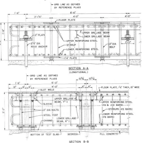
Fig. 3. shows typical cross-sections throush the floor. Steel embedded in the Jtab consists mainly of three groups:
(a) reinfolcing steel providing flex-ural and shear strength in the slab
(b) structural steel providing for resistance to horizontal forces devel-oped during tests
(c) additional structural steel pro-vided melely for accurate positioning and support of steel members (b).
Trvo-'uvay reinforcing (a) was de-signed for the bending moments and
shears, under tne assumptron that the slab acts in strips and distributes up-ward forces introduced at the column bases to the nearest group of rock anchors.
T,he embedded structural steel listed as (b) consists of "floor plates" flush with the floor and of pairs of longi-tudinal I-beams which r-un directly beneath the floor surface and are welded to the floor plates. These I-beams were designed to take the zontal forces produced by the hori-zontal application of a 50 ton jack at a column base.
As stated earlier the additional structural steel (c) in the slab served to achieve the required accurate posi-tioning of the floor plates with a tolerance of -+ l/16 in. during con-struction. This steel consisted of six transverse I-beams supported by short steel posts. The beams supported the longitudinal I-beams and floor plates and held them rigidly in place during placing of concrete.
As assembly of trhe complete grill-age progressed from bottom to top, more and more accurate positioning by shimming was possible, and after a complete check of dimensions the whole system was welded together into a strong unit capable of resisting all the pressures and vibrations result-ing from placresult-ing and vibratresult-ing the concrete.
Rock Anchors: The test slab was "clamped" to the underlying bedrock by means of 26 pretensioned rock anchors. The rock anchors reached
a depth of approximately l0 ft.
below the floor surface, each an-chor consisting of a 214 in. diameter high strength steel rod designed to rvithstand an upward force of approx-imately 70 tons. It was not considered necessary to design the rock anchors to twice the capacity of the column anchors since it r,vas unlikely that all rock anchors would be simultaneously loaded to capacity by the slab, rvhich is intended to serve as a load sharing member'.
Trhe actual anchorage of the rods at the Iower end was achieved by a system, devised for the purpose, which consisted of flaring the ends of the steel rods and grouting them into the bottom of the hole. This system was tested to a load of 100 tons in a rock
outcrop in a nearby quarry. The
flared end was produced by splitting the rock anchor rod crossways by two flame cuts and driving wedges from bhe bottom. The tops of the rods were threaded for pretensioning and bolting after completion of the slab.
Test Frames: The basic idea of test frames is to provide a system of reaction frames that can be assembled and bolted together in any desired manner around the test object and anchored to the slab. In some ways Fig. 3. Sections ttrough test slab.
i < G R I D L I N E ^ A S D E F I N E D
] ev nerrneruce erucs
I.-GRIO LINE AS DEFINED BY REFERENCE PLUGS
S E C T I O N B - B ( T R A N S V E R S E )
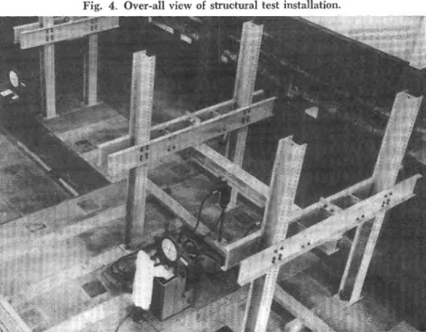
these frames thus form a giant "mec-cano" set, to which the hydraulic jacks are bolted. A typical test set-up is shown in Fig. 4.
Since vertical downward loading is by far the most frequent requirement, particular attention was paid to the ar:rangement of the jacks to be used for this purpose. The combination of continuous adjustment in both direc-tions in a horizontal plane makes it possible to position the jacks at any desired point over the structure, in spite of the fact that the frames them-selves can only be positioned at dis-crete points. This can be achieved by sliding trhe j[cks along the spreader to any desired point and sliding the spreader beam in the other direction under the cross beams joining the columns.
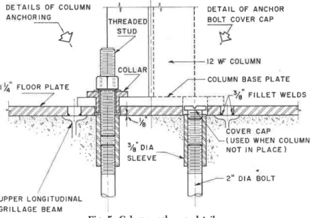
A main requirement of the test set-up is the provision of rigid joints in order to prevent slack, which would reduce the effective stroke of the jacks. This is achieved efficiently and inexpensively by the use of high ten-sile bolts ratfrrer than by accurate machining of parts as in some of the European installations. The anchorage of the frames to the slab is achieved by pairs of 2 in. diam. high-strength
steel bolts which clamp the base
olates of the columns to the floor. betails of a typical column anohorage are shown in Fig. 5. The system used provides a clear separation between the vertical and horizontal anchorage. Horizontal displacement of the column base plate, which would endanger the threaded anchor bolts, is prevented by two tightly fitting 3)4 in diam. collars which protrude through the column base plate into holes in the floor
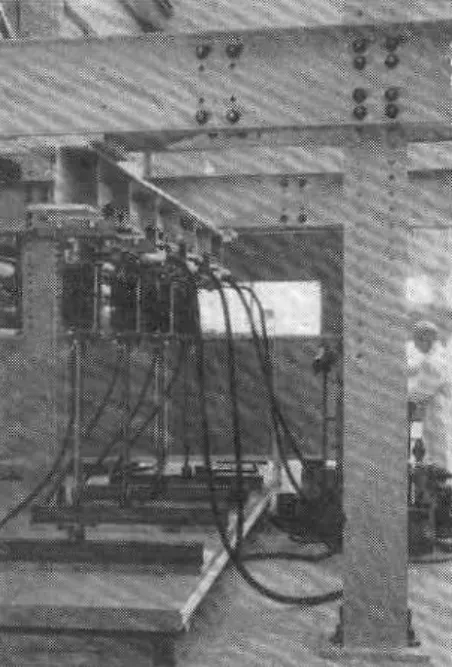
plates. Each column anchorage is de-signed to resist a static force of 50 tons in either upward or horizontal direction. After assembly of a column anchorage, the anchor bolts are pre-tensioned by means of a simple hy-draulic jacking system (Fig. 6.) pro-ducing an upward force of approx-imately 30 tons while the nut on the bolt is tightened.
The test frames consist of ordinary structural steel members. As a first in-stalment intended to serve many of the anticipated ordinary needs, the follorving main members were ac-quired:
6 columns 12 \ F 85, 16 ft. long; 2 cross beams, pairs of 18 L--: 58,
16 ft. long;
I cross beam, pair of 18 t-t 5E, 11 ft. long;
2 spreader beams, 12VF 106, 14 ft. 9 in. long;
5 supports for spreader beams or jacks;
4 diagonal struts, 10 W 33 with
stub columns.
These members are shown in Fig. 4, with the exception of the diagonal struts which serve to give horizontal suppolt to trhe top of the columns when greater horizontal forces are involved.
Connections between the different members, with the exception of that between the spreader beam and the cross beam are made by 1 in. diam. high tensile bolts. This method offers the advantage of achieving complete joint rigidity without requiring ac-curately macrhined parts, ease of assembly and disassembly and better resistance to fatigue loading (in case
such testing becomes necessary in the future). The bolts are tightened to the required 700 to 800 foot pounds by means of a special tolque
wrench or a pneumatic impact
rvlench.
The 1 3/16 in. diam. bolt holes are laid out in a 3 by 6 in. patteln on the members. One inch diameter high strength bolts ale used in all ordinary work since the clamping force pro-duced would eliminate any joint
slip-page up to working loads. Bolts 116 in.
diam. could, however, be used in case of exceptionally high loading where frame movement resulting from joint slippage might become a factor.
Load-Produci.ng and Measuring
Equipment: The hydraulic loading
equipment consists essentially of
portable hydraulic jacks fed from a pump in the pendulum dynamometer which serves to measure the load pres-sure applied with high accuracy. The Ioading equipment is made by a Swiss firm which has had extensive exper-ience in the manufacture of this type of loading equipment.
The hydraulic compression jacks are of the lapped piston type in r'vhich the friction between the piston and the cylinder is reduced to a minimun so trhat the oil pressure can be used to indicate the load applied with consid-erable accuracy.
The hydraulic equipment available consists of tthe following mair' parts: 2 hydraulic jacks of 50 ton capacity; 2 hydraulic jacks of 10 ton capacity; 8 hydraulic jacks of 5 ton capacity; 4 hydraulic jacks of 21i ton capacity;
2 pendulum dynamometers, both
equipped with hydraulic load
maintainers;
t distributor used when necessary to distribute the oil from one pendn-lum dynamometer to a number of jacks;
Various high-pressure flexible
hoses and miscellaneous access-ories.
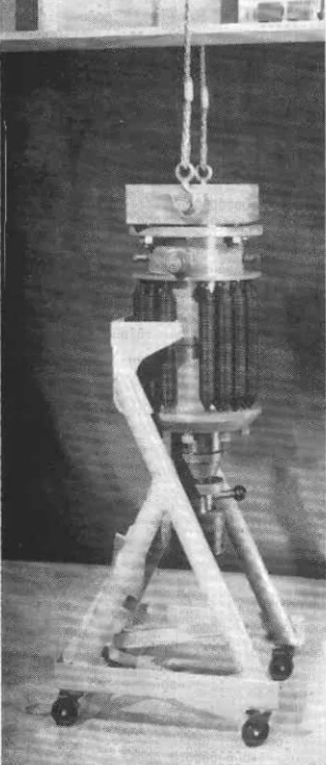
All jacks have a piston stroke of 5 in. The coil springs seen on the out-side serve to compensate for the piston weight in the inverted position, and pull the piston back when unloading. Spherical seats are provided at both ends to ensure true axial loading
through the jack. (Flg. 9.)
The same jacks can be used for dynamic or fatigue loading if fed from special pulsators which are made for this purpose. For the time being the installation is not equipped for dy-namic testing.
The pendulum dynamometers have the double function of supplying oil pressure to the jacks and of measur-ing the load; this is done with the
- a - i r i t I {
same accuracy as in ordinary univers-al testing machines. Trhe hydraulic pressure fed to the jacks acts on a measuring piston, which in turn pushes against the pendulum. A high-er pressure on the piston is balanced by the higher swing of the pendulum, and the movement of the pendulum is transmitted to a large dial on the front of the cabinet. The measuring piston is constantly rotating about its own axis, thereby practically elimin-ating friction.
The pendulum dlmamometer pro-vides four load ranges for all jacks. The sm'allest gradation of the srnal'l-est jack in the smallsrnal'l-est range is one pound. In contrast, the maximum ca-pacity of the largest jack in the largest range is 112,000 lb. or 50 metric tons. An autom,atic load maintainer al-lows application of constant loads over long periods of time, independent of the deformation of the structure. This feature is particularly valuable for creep tests on structures or when it is desired to maintain one load while varying another. The pendulum dynamometers can easily be moved and need not be bolted to the labora-tory floor.
Construction of Slab
It was realized at the outset that the complete interchangeability of component locations would require close control of dimensions during construction of the slab base. It wai therefore decided to establish erid control points on brass plugs set inlhe floor along lines of a very accurate rectangular traverse established iust outside the excavation area. Usine precise triangulation and chaining methods along with careful scribing of the brass plugs, the grid conhol points were made sufficiently accurate to allow location of any point over the excavation area within -+ 1/64 in. by means of a transit set up over the proper control points. The accur-acy of the horizontal dimensional con-trol system was therefore about twice trhat of the tolerance specified for dlilling the anchor holes in the slab bed plates and four times that of the tolerance specified in the final loca-tion of the anchorage points.
The original laboratory flool was slightly sloped for drainage but it was decided to make the test slab surface as nearly horizontal as possible. The top elevation of the slab was set to be the same as the highest point of []re surrounding floor adjacent to its pelimeter. A rounded brass bench mark was set in concrete in a stable location for use in controlling the vertical location of the test slab.
As noted befole, the plrrn of the slab lvas arranged to make use of some
\,:'{
I 3 4 ' o t a S L E E V E U P P E R L O N G I T U D I N A L G R I L L A G E B E A Mrock anchors already existing under the original laboratory floor. For con-venience, the holes for additional new rock anchors were drilled through the existing floor down to the required level in the bedrock before any exca-vation for slab construction was started.
Construction of the new test slab was begun by sawing through the existing floor with a concrete saw on lines 1/z in. outside the perimeter of the new slab location. The concrete removed was broken up with iack hammers and all material including crushed rock below the floor slab was excavated down to bare rock using a small backhoe and a conveyor for loading trucks.
The design depth of the test slab was 3 ft. 2 in. and the average depth of bedrock below the general labor-atory floor proved to be 4 ft. I in. A layer of fill concrete was therefore cast over the whole floor of the exca-vation to bring the working level up to that assumed in the design and to provide a level working area.
Short steel posts were set vertically, with their lower ends embedded in the fill concrete and their top ends adjusted to an elevation sligrhtly below that required to support six transverse I-beams, which in turn would carry the longitudinal I-beams and bed plates (Fig. 8). Sma,ll steel channels rvere also embedded in the top sur-face of the fill concrete to which the nuts and anchor plates for the column anchor bolts were later welded for accurate positioning.
Excavation of the slab area ex-poseC the previously drilled rock an-chor holes. Since the rock anan-chors were to be installed after the test slab r,vas completed, short lengths of pipe welc placed over the rock anchor lioles to keep concrete from entering
D E T A I L O F A N C H O R B O L T C O V E R C A P C O L U M N B A S E P L A T E F I L L E T W E L D S ( U S E D W H E N C O L U M N N O T I N P L A C E ) 2 . ' D I A B O L T
them and to enable the rock anchors to be lowered down through the slab at a'later date (Fig. 8).
Following completion of the fill concrete, a low concrete block wall was built ar0und the perimeter of the excavation beneatih the exposed edges of the old floor slab to support them. To this low wall was nailed a layer of 1i.in. asphalt impregnated ffbre-board which was placed to isolate the test slab from the general laboratory floor, so insulating it from the rest of the buitrding. This was done in ,onder to reduce vibrations in the rest of the building if and when tihe test installation was used for fatigue test-ing in the future.
The contractor then proceeded to place the transverse and longitudinal I-beams, the reinforcing steel, and the column anchor rods. The latter were greased and wrapped with tar paper to prevent bond with the concrete, so that when later pretensioning loads were applied they would be trans-mitted directly to the bottom anchor plates at the base of the slab. The rods were then screwed into the nuts below the plates, and after careful plumbing they were tack welded to the plates which in turn were tack welded to the small channels em-bedded in the fill concxete.
At this point the longitudinal I-beams were shimmed into proper posi-tion and the floor plates placed irr approximate position. Members of the Division's staff then carefully set the plates for line and level and clamped them into position. The contractor proceeded to weld the several sections of the plates together and to weld the complete plates in turn to the longi-tudinal I-beams. Although a welding sequence was used that would min-imize rvarping, it was necessary at trhis stace to check the levels of the
A I L S O F C O L U M N H O R I N G .-l
\
F L O O R P L A T E \ . 1plates constantly and to correct, by iudicious shimming, changes in level caused by welding.
The final operation prior to con-creting was to place small wooden forms over the top of the existing rock anchors and pipe openings left for new rock anchors. These were placed to form pits 15 by 15 in. by I ft. 6 in. in the test slab surface (Fig. 2). Trhese extended down to a level just below the tops of the rock anchors, which were intended to have their' tops about 8 in. below the slab sur-face.
Ready-mixed concrete with 4000 p.s.i. compressive strength at 28 days was specified for the main mass of the slab. The aggregates used were a local crushed rock aggregate and sand. Although the heavy slab rein-forcement was rather closely spaced and the concrete mix rather stiff in consistency, the concrete was readily vibrated into place with very little segregation and, it is thought, very little if any honeycombing or voids. A 2 -+ 16 in. slump was maintained by making tests of every truck load of concrete received and at least one compression test cylinder from every second load. After' 28 days' standard curing the average strength of the test cylinders was 4080 p.s.i. with a minimum of 3810 p.s.i.
The top surface of the main body of the slab concrete was struck off about 7+ in. below ttrre bottom of the steel base plates, and after 24 hr. members of the laboratory staff care-fully dry-packed the space below the base plates with a dry mortal mix to make virtually certain that the plates would, not be separated from the
con-crete by settlement of the slab but would have positive bearing. This was considered necessary as tests conducted before construction indi-cated that the 3 ft. depth of concrete could settle away from the plates by about 1/16 in. After this operation the contractor brought the slab concrete up to the level of the top of the base plates by placing a 2 in. layer of finish conclete containing ,16 in. trap rock aggregate for hardness and abla-sion resistance. Welded wit'e mesh was placed in the centre of the layer. A commercial curing compound was sprayed onto the concrete.
By careful checking and adjusting during all phases of construction a sensibly flat slab was achieved, so that with one minor exception, the deviation fi'om the specified elevation of the anchor points was less than 1/16 in. Without this care the devia-tion would have been much greater' owing to trhe natural variation of dimensions of all the slab components, workmanship errors, and the tendency for such glillage to warp when welded.
In the three years since construc-tion, close inspection of the slab shows it to be in excellent condition and re-markably free of surface cracks. The latter is partly due to the fact that the finish concrete is divided into sections by ttrre steel bed plates. Installation and Tensioning of Rock Anchors
Three months after construction of the test slab, the flared end of an anchor rod was lowered through the pipe sleeves in the slab into bedrock. The lower end was about 7 ft. in the
Fig. 7. Loading test on Arctic housing roof panel with four jacks.
rock and the upper end approximately 8 in, below the slab surface and ex-posed in the small t5 by 15 in. access pit. A 20 ft. length of 16 in. O.D. copper tubing was lowered to the bottom of the lock anchor hole alongside the anchor rod. Clean, ?6 in. traprock aggregate was dropped into the hole until a plug of stone 20 in. deep was formed around the flared end of the rod (extending about 12 inches above trhe top of the flare). Neat cement grout consisting of 51L gal. of water per sack of high early strength cement plus 50 cc of Plasti-ment was then pumped through the copper tube until it completely filled the voids in the traprock plug. The amount of grout necessary was Pre-viously determined by calculation and experiment. In the grouting operation grout was poured into the copper tube through a funnel and pressure ap-plied to it with a pump improvised from a caulking gun.
The rock anchors were pretensioned to about 65 tons, which was just be-low the yield point of the rods at the loot of the threads. The prestress-ing opelation was commenced four months after the rock ancrhors rvere installed. A 12 by 12 by 2 in. plate washer was placed over the top of each rock anchor and floated to even bearing on a bed of cement mortar at the bottom of the access pit (Fig. 3). When the bedding mortar ihad gained sufficient strength a nut was turned onto the rock anchor and tighlened by hand against the plate washer. By means of a threaded sleeve, the lower end of an extension rod rvas then fastened to the ton of tl're lock anchor and the upper end coupled to a 100
, ) ( 6 4 ! t k q l
l@'{ltr,itt
lt"6;.@;@.b.r
'9"+
*++
P)d] s @ton centre-hole jack supported by a small reaction frame. A 65 ton load was then applied to the rock anchor', the nut at the bottom of the access pit tightened by special socket wrench and the jack pressures released, leav-ing the rock anchor Dreterrsioned.
As a final step, 4'/, in. un-r'einforced concrete slabs were cast in place to provide semipermanent covers over each pit. From time to time one or more of these slab covels will be broken out to check prestress'losses.
Handling of Testing Equipment Considerable attention was given jn hhe design of the installation to the convenience of assembling and dis-mantling the components of test frames and of the hydraulic loading equipment. The members of the fi'ame were equipped with holes for easy lifting by means of the 10 ton laboratory crane. Thanks to the ac-curacy of column anchorage points, it has been found possible to leave en-tire bents assembled, while moving bhem to different locatiorrs.
Since the hydraulic jacks are most frequently used in their "hanging"
1.j
Fig. 8. Excavation for test slab after placing of steel posts, bottom plates for column anchorages and part of lower reinforcing steel.
position, it was decided to store them also in this way. All except the heavy 50 ton jacks are kept on a storage rack from which they can be trans-ferred by sliding them onto a dolly which is then wheeled under the de-sired point on the test frame. From there the jacks are hoisted by means of a crane and double sling and at-tached by special bolts and brackets to the underside of the spreader beam. A similar arrangement is used fol the 50 ton jacks, but because of their f400 lb. weight, they are kept per-manently on the dolly and are not transferled to a storage rack. (Fig. 9). When the jacks ale used under a single bent, as shown on the left on Fig. 4, a different attachment is used. The saddle support which normally carries the spleader beams is pro-vided with a special hanger plate with holes at appropriate places to support the jack.
Use of Installation and Final Remarks The installation rhas been used for Ioading tests on a valiety of structural items including timber bridge planks (l-ig. a), prefaibricated Arctic housing panels (Fig. 7), sections of wooden loof trusses, conclete and masonry rvalls subjected to combined verticai and lateral loading. It will shortly be used for loading tests on an en-tire house roof.
It may be noted that during the test of masonry walls both pendulum dynamometers were used simultane-ously, one to plovide quarter-point horizontal loads on the face of the wall, the othel to keep, with the aitl of the builrin load maintainer, a con-stant vcrtical load on the wall.
In conclusion it can br: strrted thrt
the system of structural testing equip-ment adopted, consisting of an anchor-age slab, reaction frames and portable hydraulic jacks, has provided the Di-vision of Building Research with an extremely versatile structural testing installation, suitable for full-scale load-ing tests on a wide variety of struc-tural elements. Experience to date with the installation has been entirely satisfactory. lt is expected that, as the work of .the Building Structures Section expands, the installation will be used more and more. Furbher parts will be added to the test frames and the hydraulic loading equipment as the need arises. It is believed that this new installation of the Building Re-search Centre will fill an important role in making available for service to the Canadian construction industry the best possible building research facilities.
Acknowledgements
The authors wish to express their appleciation to trhe many persons who generously contributed their services and experience to the successful de-velopment of the installation, par-ticularly to members of staff of the laboratories listed at the beginning of the paper and especially to Dr. Bruno Thiirlimann of Lehigh University, Bethlehem. Pa.. for information lead-ing to the general scheme of the installation. The autrhors are indebted to Dr. Sheldon Cherry for valuable assistance with the structural design of the slab and test frames. This paper is a contribution from the Division of Building Research of the National Research Council of Canada and is publishcd rvith the approval of thc Director of the Divisiol.
Fig. 9. Fifty-ton jack being lifted from dolly to test frame.